EP0858611B1 - Vorrichtung und verfahren zur selektiven rasterung oder anvisierung eines signals - Google Patents
Vorrichtung und verfahren zur selektiven rasterung oder anvisierung eines signals Download PDFInfo
- Publication number
- EP0858611B1 EP0858611B1 EP96926232A EP96926232A EP0858611B1 EP 0858611 B1 EP0858611 B1 EP 0858611B1 EP 96926232 A EP96926232 A EP 96926232A EP 96926232 A EP96926232 A EP 96926232A EP 0858611 B1 EP0858611 B1 EP 0858611B1
- Authority
- EP
- European Patent Office
- Prior art keywords
- axis
- drive
- optical signal
- bearing
- ring
- Prior art date
- Legal status (The legal status is an assumption and is not a legal conclusion. Google has not performed a legal analysis and makes no representation as to the accuracy of the status listed.)
- Expired - Lifetime
Links
- 238000000034 method Methods 0.000 title description 7
- 230000003287 optical effect Effects 0.000 claims description 44
- 230000036316 preload Effects 0.000 claims description 3
- 230000008054 signal transmission Effects 0.000 claims 1
- 230000002093 peripheral effect Effects 0.000 description 8
- 230000001419 dependent effect Effects 0.000 description 3
- 239000011248 coating agent Substances 0.000 description 1
- 238000000576 coating method Methods 0.000 description 1
- 238000001514 detection method Methods 0.000 description 1
- 239000011521 glass Substances 0.000 description 1
- 230000005484 gravity Effects 0.000 description 1
- 238000007789 sealing Methods 0.000 description 1
- 230000000007 visual effect Effects 0.000 description 1
Images

Classifications
-
- G—PHYSICS
- G02—OPTICS
- G02B—OPTICAL ELEMENTS, SYSTEMS OR APPARATUS
- G02B26/00—Optical devices or arrangements for the control of light using movable or deformable optical elements
- G02B26/08—Optical devices or arrangements for the control of light using movable or deformable optical elements for controlling the direction of light
- G02B26/10—Scanning systems
- G02B26/105—Scanning systems with one or more pivoting mirrors or galvano-mirrors
-
- Y—GENERAL TAGGING OF NEW TECHNOLOGICAL DEVELOPMENTS; GENERAL TAGGING OF CROSS-SECTIONAL TECHNOLOGIES SPANNING OVER SEVERAL SECTIONS OF THE IPC; TECHNICAL SUBJECTS COVERED BY FORMER USPC CROSS-REFERENCE ART COLLECTIONS [XRACs] AND DIGESTS
- Y10—TECHNICAL SUBJECTS COVERED BY FORMER USPC
- Y10S—TECHNICAL SUBJECTS COVERED BY FORMER USPC CROSS-REFERENCE ART COLLECTIONS [XRACs] AND DIGESTS
- Y10S359/00—Optical: systems and elements
- Y10S359/90—Methods
Definitions
- the present invention relates to a scanning and aiming devices, and more particularly, to a device for selectively receiving or sending a signal in a spherical manner around said device, while maintaining a stable, non-rotated image having minimal distortion.
- a periscope is a commonly known device for redirecting an optical image.
- Periscopes are used to observe a field of view without exposing oneself, or a piece of equipment, to danger or detection.
- Periscope type devices are used both on submarines and on land.
- the devices typically use two flat mirrors positioned in a tubular column such that the signal inlet end can be located remote from the signal outlet end. Since the field of view in these devices is relatively narrow in a horizontal plane, the column must be rotated to increase the field of view within that plane. This is true even when optical lenses are used to increase the field of view. In order to view in a vertical plane, the column must be tilted or one of the mirrors pivoted.
- periscope is disclosed in US-A-4 787 725.
- This periscope is a panoramic periscope having a ray path for the visual observation of objects and having a central tube with an ocular or eyepiece disposed laterally thereon, the central tube being provided with a system of lenses, prisms and mirrors and having a peripheral viewing window which is mounted so as to be rotatable about the longitudinal axis of the central tube through 360° or more, the window being mounted in a viewing hood disposed above the central tube and lying at an angle relative to the longitudinal axis of the central tube, the window being radially disposed in a viewing housing which has a reversing prism or the like and is mounted so as to be additionally rotatable about its own longitudinal axis at an angle relative to the longitudinal axis of the central tube, characterized by a system of prisms, and/or mirrors which is constructed in such a manner that, when the viewing window is rotated from a position on one side of the zenith to
- Another example is security cameras, in order to increase the field of view the whole camera is typically rotated in either one or sometimes even two axes. This usually leaves the camera exposed, leaving it vulnerable to damage or avoidance.
- One solution places the camera in a semi-spherical bubble with a one-way mirror coating.
- Another problem with moving the entire camera is the location of its center of gravity and hence the inertial factors associated with moving the camera about one or more axes in order to scan an area. This and other problems are addressed by the present invention
- a major problem area in the scanning arts involves mounting a scanner to an outer surface of an aircraft or satellite.
- One problem is to maintain the largest possible scan field while at the same time maintaining the quality of the scanned image (signal received).
- Another problem is in sealing the scanner from the outside environment, or lack thereof in the case of satellites
- Prior art devices have addressed some of the problems noted above with limited success.
- the present invention provides a method and apparatus for selectively scanning a spherical range of signal sources.
- a pair of signal diverters independently rotate about respective axes passing through a central portion of each diverter.
- the diverters are driven by at least one motor
- the axes passing through said diverters intersect at substantially ninety degrees, with the intersection occurring within the plane of one of the diverters.
- the signal diverters are flat mirrors, although refractive optical elements could be used dependent upon the signal of interest and the type of sensor used
- signal diverters are surfaces designed for maximum signal diversion with minimal distortion. Signal diverters will vary dependent upon the signal of interest and the type of sensor used.
- a camera can be used as the signal sensor.
- the camera rotates the same number of degrees as does the mirror that is rotating.
- the camera will rotate at the same angular velocity as the algebraic sum of the two mirrors, e.g., when viewed from the camera, if both mirrors rotate in a clockwise direction, the camera will rotate the same number of degrees as do both mirrors, if one mirror is rotating in an opposite direction, the camera will only rotate an amount equal to the number of degrees rotated by the mirror rotating in a clockwise direction minus the number of degrees rotated by the other mirror (which is rotating counterclockwise).
- one mirror has a Y-axis of rotation that passes through a central portion thereof
- the Y-axis mirror is supported by a pair of side walls, which are attached to a bearing ring.
- the bearing ring has an opening therein allowing an image reflected by the Y-axis mirror to pass therethrough.
- the X-axis mirror rotates about an X-axis passing through a central portion thereof, with the X-axis passing through a central portion of the camera's lens.
- drive belts are used to connect the drive motor with the mirrors and camera There are two belts driven directly by the motor's shaft, one drives the camera mounting ring and the other drives a primary drive ring.
- the primary drive ring is juxtaposed to the X-axis mirror drive ring, being separated by a bearing.
- a rotary solenoid is used in conjunction with a spring to engage a drive belt around just the X-axis drive ring providing a friction brake to ensure that the X-axis mirror does not move when the primary drive ring is driving the Y-axis drive ring.
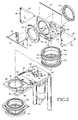
- a directional scanner 10 is shown. While scanner 10 can be used to direct a signal, such as a laser beam, the following description is based upon an incoming signal
- the incoming signal can be any type of sound, radio, or light wave.
- the embodiment described herein is for use with light wave energy.
- Scanner 10 has a first objective mirror 12 and a second objective mirror 14.
- Mirror 14 is supported for rotation about an X-axis passing therethrough
- Mirror 14 is mounted at a forty-five degree angle with respect to said X-axis.
- mirror 12 is supported for rotation about a Y-axis passing therethrough. (See Fig. 3)
- a mirror rotation means 16 provides the necessary torque to rotate mirrors 12 and 14
- Support means 18 includes a drive mounting portion 24 for receiving drive means 26.
- Support means 18 also includes a bearing surface means 28 for receiving mirror assembly 22.
- Bearing surface means 28 may include a ball bearing race 29 formed therein, or may include a counterbore for receiving a bearing race.
- a drive train means 30, for connecting drive means 16 to mirror assembly 22 includes the use of a primary drive belt 32.
- Belt 32 connects drive means 16, with a primary drive ring 34 of mirror assembly 22.
- Drive means 16 can be any suitable rotary motor 26, such as an electric motor, and is preferably a low voltage motor in the range of fourteen to twenty-eight volts
- a sensor drive belt 36 connects drive motor 26 with a sensor drive ring 38
- a sensor (not shown) such as a video camera, is attached to sensor ring 38 in a manner that allows the sensor to rotate with the ring.
- First mirror 12 is supported by a pair of side supports 40.
- Mirror 12 is adhesively attached to side supports 40.
- Side supports 40 are in turn attached to a Y-axis drive ring 42
- Side supports 40 hold first mirror at a forty-five degree angle with respect to drive ring 42
- Incorporated into one side of ring 42 is a ball-bearing race 44 (see Fig. 4).
- a drive belt receiving groove 46 is formed in the peripheral edge of ring 42
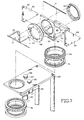
- a right angle support member 48 includes a Y-axis plate 50 and an X-axis plate 52.
- Each plate, 50, 52 has an opening therein allowing an incoming signal to pass therethrough Y-axis plate 50, which is perpendicular to the Y-axis, has a bearing race formed on each side thereof Said bearing races having the same diameter as bearing race 44.
- a Y-axis retaining ring 54 having a bearing race formed on one side thereof is used to hold ball bearings between ring 54 and Y-axis plate 50 and between ring 42 and Y-axis plate 50, thereby allowing ring 42 to rotate about the Y-axis Y-axis bearing screws 56 hold ring 42 and retaining ring 54 together (see Figs. 4 and 6).
- a standard ball or roller bearing arrangement could be used, with the outer race of such a bearing being seated into Y-axis plate 50.
- Second mirror 14 side supports 58 are fastened to Y-axis plate 50 and X-axis plate 52. Side supports 58 have a second mirror mounting edge 60 which form a forty-five degree angle with the X-axis. Second mirror 14 is adhesively attached to mounting edges 60 A counter balance weight 62 may be added to rear edge 64 of X-axis plate 52 in order to balance the weight of first mirror 12 and its associated drive ring 42 and bearings and Y-axis plate 50
- X-axis plate 52 has an opening 66 therein such that signals (light) can pass therethrough.
- a bearing race 68 is formed in the bottom of plate 52
- Primary drive ring 34 hereinafter referred to as combination drive ring, has a first mirror drive belt groove 72 and a primary drive belt groove 74 formed therein.
- the operation of drive train 30 is described below
- Combination drive ring 34 has bearing races formed on both sides thereof
- An X-axis drive ring 76 is located below combination ring 70.
- Drive ring 76 also has bearing races formed on its top and bottom surfaces.
- Bearing surface means 28 is located below drive ring 76 and has corresponding bearing races 29 formed on its upper and lower surfaces and is held against rotation by support member 20.
- Sensor drive ring 38 is located below bearing surface 28 and has bearing races formed in its top and bottom surfaces.
- a bearing retaining ring 78 is located below sensor ring 38 and has a bearing race formed only in its top surface.
- Threaded rods 80 connect bearing retaining ring 78, X-axis drive ring 76 and X-axis plate 52 such that the three components rotate together when ring 76 is rotated by drive train 30.
- Ball bearings are placed between each respective pair of bearing races and the bearing pre-load adjusted by tightening or loosening threaded rods 80.
- the bearing races and bearings separating rings 42 and 54 are adjusted by tightening or loosening threaded rods 56.
- a sensor like a video camera or infra-red detector, have a limited field of view, it is desirable to expand that field of view while maintaining good image quality and preferably avoiding image rotation.
- the sensing device is attached to sensor drive ring 38 in a conventional manner Hence, whenever drive motor 26 is energized, sensor ring 38 will rotate through the same angle and/or at the same rate as either Y-axis drive ring 42 or X-axis drive ring 76. This motion dictates that a viewed image will remain normal in appearance on a display monitor.
- the field of view of the present invention is almost spherical, except for a small conical area above and below second mirror 14, these areas being located along the X-axis. If it is important to see these areas, first mirror 12 can be adjusted to allow the noted areas to be included in the field of view, at the expense of image quality, since distortion of the image will occur. It should also be noted that mirrors 12, 14 could be replaced by other optical devices, such as prisms, dependent upon the application of the invention
- Drive train 30 further includes a rotary solenoid 82, a drive ring brake 84 and an idler wheel 86.
- a rotary solenoid 82 When primary drive belt 32 moves in response to drive motor 26 being energized, combination drive ring 34 rotates. This is true because X-axis drive ring 76 is held in position by brake 84, which is urged against ring 76 by spring 87.
- Y-axis drive ring 42 is connected to combination drive ring via a Y-axis drive belt 88 and a pair of idlers 90 that change the direction of drive belt 88. In this manner, first mirror 12 is rotated, providing a scan the width of mirror 12 in an arc of 360°.
- solenoid 82 is energized thereby pulling brake 84 away from drive ring 76 and engaging idler wheel 86 between primary drive belt 32 and drive ring 76
- This action rotates second mirror 14 around the X-axis while first mirror 12 remains stationary relative to second mirror 14.
- an arc of 360° around the X-axis is scanned
- sensor ring 38 is rotated an equal amount, thereby keeping the scanned images in a normal position on a display monitor.
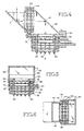
- FIGs 7 and 8 A and B
- another embodiment of the invention is shown that utilizes gears instead of belts.
- Fig. 7 is an embodiment of the present invention using a plurality of drive motors, this embodiment is described in detail below.
- motor 126 has a drive gear 132 attached to its shaft Drive gear 132 either directly or through a set of reduction gears (not shown) drives primary drive ring 134, which has gear teeth formed in an edge portion around its periphery
- primary drive ring 134 includes a second set of gear teeth 135 that mesh with, and drive, a pinion gear 137 that meshes with, and drives, Y-axis drive ring 142.
- Drive ring 142 has gear teeth formed on a peripheral edge portion thereof.
- An X-axis drive ring 176 includes gear teeth formed on a peripheral edge portion thereof.
- An idler gear (not shown), similar to idler wheel 86 shown in Fig. 2, except this idler has gear teeth thereon that mate with the gear teeth on drive ring 176
- Camera drive ring 138 also has gear teeth formed on a peripheral edge portion thereof and is driven either directly or through a gear train by motor 126.
- a camera drive motor 125 is mounted to support member 120 Mounted on motor 125 shaft is a pinion gear (not shown)
- the pinion gear drives camera drive ring 138, which has gear teeth formed on a peripheral edge portion thereof.
- An X-axis drive motor 126 mounted on support member 120, includes a pinion gear 132 attached to its shaft Pinion gear 132 either directly or via a gear train drives X-axis drive ring 176, that includes gear teeth formed on a peripheral edge portion thereof.
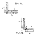
- a Y-axis drive motor 127 mounted on support member 120, includes a pinion gear 133 attached to its shaft. Pinion gear 133 either directly or via a gear train, drives primary Y-axis drive ring 134. Secondary Y-axis drive ring 142 has gear teeth formed on a peripheral edge portion thereof and is driven either directly or indirectly by drive ring 134 As shown in Figs 8A and 8B, primary Y-axis drive ring 134 can mesh directly with drive ring 142 or through a reversing gear 145
- Each motor, 125, 126, and 127 are independently controlled.
- Y-axis motor 127 can be a reversing motor, so long as that aspect is taken into account by the control system.
- Drive motor 125 must be able to turn camera drive ring 138 at a rate equal to the sum of motors 126 and 127. Whenever either X-axis or Y-axis drive motors 126, 127 are energized, motor 125 must turn at the same rate in order to prevent image rotation.
- the invention has many applications for directing or receiving either sound or light waves.
- the invention can be used to conceal a video camera with a vehicle or building with only a small portion extending beyond the outer surface of the vehicle or building thereby providing concealment and protection.
- the device has both military and civilian uses.
Landscapes
- Physics & Mathematics (AREA)
- General Physics & Mathematics (AREA)
- Optics & Photonics (AREA)
- Image Input (AREA)
- Analysing Materials By The Use Of Radiation (AREA)
- Studio Devices (AREA)
- Testing, Inspecting, Measuring Of Stereoscopic Televisions And Televisions (AREA)
- Vehicle Body Suspensions (AREA)
- Investigating Or Analysing Materials By Optical Means (AREA)
- Optical Radar Systems And Details Thereof (AREA)
- Stereoscopic And Panoramic Photography (AREA)
- Rear-View Mirror Devices That Are Mounted On The Exterior Of The Vehicle (AREA)
Claims (12)
- Optische Abtastvorrichtung (10) zum Abtasten eines im wesentlichen sphärischen Sichtfeldes, wobei der optische Abtaster umfasst:wobei das drehbare Halterungsmittel weiter ein Mittel zum Bewegen des ersten optischen Signalumlenkers um die X-Achse umfasst, wenn der zweite optische Signalumlenker sich derart um die X-Achse dreht, dass der erste optische Signalumlenker (12) ein optisches Abtastsignal von einer ausgewählten abgetasteten Stelle empfangen kann und das optische Abtastsignal zu dem zweiten optischen Signalumlenker (14) übertragen kann;Einen ersten optischen Signalumlenker (12) angeordnet in einer Ebene, die mit einem vorbestimmten Winkel zu einer Y-Achse festgelegt ist;einen zweiten optischen Signalumlenker (14) angeordnet in einer Ebene, die mit einem vorbestimmten Winkel zu einer X-Achse festgelegt ist; wobei die Y-Achse senkrecht zu der X-Achse ist und durch die Ebene des zweiten optischen Signalumlenkers geht; unddrehbare Halterungsmittel (32,34,42,88) umfassend eine erste drehbare Halterung, auf der der erste optische Signalumlenker zum Drehen des ersten optischen Signalumlenkers (12) um die Y-Achse angebracht ist, und eine zweite drehbare Halterung, auf der der zweite optische Signalumlenker zum Drehen des zweiten optischen Signalumlenkers (14) um die X-Achse angebracht ist,
dadurch gekennzeichnet, dass das drehbare Halterungsmittel weiter eine drehbare Kamerahalterung (38) zum Drehen um die X-Achse umfasst, welche dafür ausgelegt ist, eine Kamera daran befestigt aufzunehmen und ein Mittel zur Übertragung des optischen Abtastsignals zu einer entfernten Stelle umfasst, wo das optische Abtastsignal verarbeitet werden kann, wobei der zweite optische Signalumlenker (14) derart konstruiert und angeordnet ist, das optische Abtastsignal zur Kamera zu übertragen, und die drehbare Kamerahalterung dafür ausgelegt ist, die Kamera mit der gleichen Winkelgeschwindigkeit wie die algebraische Summe der Winkelgeschwindigkeiten des ersten und des zweiten optischen Signalumlenkers, wie von der Kamera entlang des Übertragungswegs des optischen Abtastsignals aus gesehen, zu drehen, ungeachtet dessen, ob der erste und der zweite optische Signalumlenker sich zur gleichen Zeit, unabhängig oder mit unterschiedlichen Geschwindigkeiten drehen, und sollten sich die Umlenker in entgegengesetzten Richtungen drehen, wird die Winkelgeschwindigkeit des einen optischen Signalumlenkers von der Winkelgeschwindigkeit des anderen optischen Signalumlenkers abgezogen. - Vorrichtung nach Anspruch 1, wobei der vorbestimmte Winkel für den ersten und den zweiten optischen Signalumlenker im wesentlichen fünfundvierzig Grad zu ihrer jeweiligen Achse beträgt.
- Vorrichtung nach Anspruch 1 oder 2, wobei das drehbare Halterungsmittel umfasst;
einen Motor (26),
einen Antrieb (30, 32),
einen Umlenkeraufbau, und
ein Tragelement (20),
wobei der Motor und der Antrieb auf dem Tragelement angebracht sind, und der Umlenkeraufbau drehbar an dem Tragelement angebracht ist. - Vorrichtung nach Anspruch 3, wobei der Umlenkeraufbau einen Lagertragrahmen umfasst, wobei der Tragrahmen eine Y-Achsenplatte (50) und eine X-Achsenplatte (52) aufweist, wobei jede senkrecht zu ihrer jeweiligen Achse steht, ferner jede Platte ein zugeordnetes Lagermittel zum Halten der Umlenker in einer drehbaren Art und Weise aufweist.
- Vorrichtung nach Anspruch 4, wobei das Lagermittel umfasst: auf beiden Seiten jeder Platte eine hier ausgebildete Laufbahn, einen Y-Achsenlagerring, der eine auf einer Seite davon ausgebildete Laufbahn aufweist, einen Y-Achsenantriebsring, der eine auf einer Seite davon ausgebildete Laufbahn aufweist , wobei die Laufbahnen durch Kugellager (44) auseinandergehalten werden und der Y-Achsenantriebsring auf der einen Seite der Y-Achsenplatte angeordnet ist und der Y-Achsenlagerring auf der anderen Seite des Antriebsrings angeordnet ist, wobei ein verstellbares Befestigungsmittel den Antriebsring und den Lagerring verbindet, um eine Vorlast auf die Lager einzustellen;
und wobei das Lagermittel weiter einen X-Achsenantriebsring umfasst, der auf beiden Seiten eine hier ausgebildete Lagerfläche aufweist, und wobei das Antriebsmittel einen Kombinations-Antriebsring umfasst, der auf beiden Seiten eine hier ausgebildete Laufbahnen aufweist, wobei die Laufbahnen durch Kugellager auseinandergehalten werden und der X-Achsenantriebsring auf einer Seite des Kombinations-Antriebsrings angeordnet ist und die andere Seite auf einer Lagertragfläche des Tragelements angeordnet ist, wobei die andere Seite des Kombinations-Antriebsrings auf der X-Achsenplatte angeordnet ist und auf der gegenüberliegenden Seite des Tragelements angeordnet ist;
einen Kameraantriebsring (38), der auf beiden Seiten davon ausgebildete Laufbahnen und einen X-Achsenlagerring aufweist, der eine auf einer Seite davon ausgebildete Laufbahn aufweist, wobei die X-Achsenplatte, der X-Achsenantriebsring und der X-Achsenlagerring ein verstellbaren Befestigungsmittel aufweisen, das sie verbindet und es erlaubt, eine Vorlast auf die Lager innerhalb jeder der beschriebenen Laufbahnen einzustellen. - Vorrichtung nach einem der vorangehenden Ansprüche, wobei der erste optische Signalumlenker (12) und der zweite optische Signalumlenker (14) Spiegel sind, wobei ein Lichtsignal, das auf den der ersten optische Signalumlenker auftrifft, in Richtung zum zweiten optischen Signalumlenker gelenkt wird, und das Lichtsignal durch den zweiten optischen Signalumlenker in die Kamera gelenkt wird.
- Vorrichtung nach Anspruch 3, wobei der Motor (26) einen Geschwindigkeitenbereich von sechs bis 360 Grad pro Sekunde aufweist, und der Antrieb (30, 32) einen Primärantriebsriemen (32) umfasst, der den Motor mit einem Kombinationsantriebsring (34) verbindet, sowie einen Y-Achsenantriebsriemen (88), der den primären Antriebsring mit einem Y-Achsenantriebsring (42) verbindet, und einen Kameraantriebsriemen (38), der den Motor (26) mit einem Kameraantriebsring (38) verbindet, und einen Antriebsriemen um einen X-Achsenantriebsring, wobei der X-Achsenantriebsring mit einem Mitlaufrad (86) und einem Bremselement (84) zugeordnet ist, umfassend eine damit in Verbindung gebrachte Feder (87) und einen dieser zugeordneten Rotationssolenoid (82), wobei in einem ersten Zustand die Bremse den X-Achsenantriebsring berührt, wodurch eine Drehung desselben verhindert wird, und ein zweiter Zustand vorgesehen ist, in dem der Rotationssolenoid erregt wird, wodurch die Bremse gelöst wird und das Mitlaufrad mit dem Primärantriebsriemen und dem X-Achsenantriebsrad eingreift zur Drehung des zweiten optischen Signalumlenkers um die X-Achse, während eine Drehung des ersten optischen Signalumlenkers um die Y-Achse verhindert wird.
- Vorrichtung nach Anspruch 3, wobei der Antrieb eine Mehrzahl von Antriebsriemen, eine Mehrzahl von den Antriebsringen zugeordneter Antriebsriemen, eine Mehrzahl von den Antriebsriemen zugeordneter Riemenscheiben, ein Mitlaufrad zur Übertragung von Drehkräften zwischen zwei der Antriebsriemen, und ein durch einen Solenoid betätigtes Bremselement, das gemeinsam mit einer Feder arbeitet, um zu verhindern, dass einer der Antriebsriemen sich dreht, wenn das Mitlaufrad nicht in Berührung mit zwei der Antriebsriemen ist.
- Vorrichtung nach Anspruch 1 oder 2, wobei das drehbare Halterungsmittel einen Antrieb umfasst, der eine Mehrzahl von Motoren aufweist, die durch eine Logiksteuerung gesteuert werden, wobei der Antrieb eine Mehrzahl von Zahnrädern (134) umfasst.
- Vorrichtung nach Anspruch 1 oder 2, wobei das drehbare Halterungsmittel einen einzigen Antriebsmotor und ein Antriebsmittel zur unabhängigen Drehung des ersten und zweiten optischen Signalumlenkers umfasst, und das Antriebsmittel gleichzeitig die Kamera antreibt.
- Vorrichtung nach einem der vorangehenden Ansprüche, wobei die Kamera eine Videokamera ist.
- Vorrichtung nach einem der vorangehenden Ansprüche, wobei das Mittel zur Übertragung des optischen Abtastsignals zu einer entfernten Stelle das optische Abtastsignal zu einem Anzeigemonitor überträgt.
Applications Claiming Priority (2)
| Application Number | Priority Date | Filing Date | Title |
|---|---|---|---|
| US08/204,551 US5543954A (en) | 1994-03-01 | 1994-03-01 | Method and apparatus for selectively scanning for or aiming a signal |
| PCT/US1996/012638 WO1998005991A1 (en) | 1994-03-01 | 1996-08-02 | Method and apparatus for selectively scanning for or aiming a signal |
Publications (3)
| Publication Number | Publication Date |
|---|---|
| EP0858611A1 EP0858611A1 (de) | 1998-08-19 |
| EP0858611A4 EP0858611A4 (de) | 2000-02-23 |
| EP0858611B1 true EP0858611B1 (de) | 2002-11-13 |
Family
ID=26791173
Family Applications (1)
| Application Number | Title | Priority Date | Filing Date |
|---|---|---|---|
| EP96926232A Expired - Lifetime EP0858611B1 (de) | 1994-03-01 | 1996-08-02 | Vorrichtung und verfahren zur selektiven rasterung oder anvisierung eines signals |
Country Status (7)
| Country | Link |
|---|---|
| US (1) | US5543954A (de) |
| EP (1) | EP0858611B1 (de) |
| AT (1) | ATE227853T1 (de) |
| AU (1) | AU6645496A (de) |
| DE (1) | DE69624835T2 (de) |
| ES (1) | ES2188773T3 (de) |
| WO (1) | WO1998005991A1 (de) |
Families Citing this family (12)
| Publication number | Priority date | Publication date | Assignee | Title |
|---|---|---|---|---|
| US5696637A (en) * | 1994-08-08 | 1997-12-09 | Reliance Electric Industrial Company | Apparatus for positioning an optical line of sight within a hemispheric region |
| US5734515A (en) * | 1994-08-08 | 1998-03-31 | Reliance Electric Industrial Company | Apparatus for positioning an optical line of sight within a hemispheric region |
| US5877806A (en) * | 1994-10-31 | 1999-03-02 | Ohtsuka Patent Office | Image sensing apparatus for obtaining high resolution computer video signals by performing pixel displacement using optical path deflection |
| US6034803A (en) * | 1997-04-30 | 2000-03-07 | K2 T, Inc. | Method and apparatus for directing energy based range detection sensor |
| US6302355B1 (en) | 1999-11-02 | 2001-10-16 | Bae Systems Integrated Defense Solutions Inc. | Multi spectral imaging ladar |
| US6371405B1 (en) | 1999-11-03 | 2002-04-16 | Bae Systems Integrated Defense Solutions Inc. | Optical system for LADAR guidance application |
| US7256834B1 (en) * | 2000-03-17 | 2007-08-14 | Axis, Ab | Digital camera having panning and/or tilting functionality, and an image rotating device for such a camera |
| AU2003229118B2 (en) * | 2002-05-30 | 2009-04-09 | Cv Laser Pty Ltd | Solid state UV laser |
| AUPS266302A0 (en) * | 2002-05-30 | 2002-06-20 | Clvr Pty Ltd | Solid state uv laser |
| US7381937B2 (en) * | 2005-09-13 | 2008-06-03 | The United States Of America As Represented By The Secretary Of The Army | Image analysis and enhancement system |
| DE102006036494A1 (de) * | 2006-08-04 | 2008-02-14 | Deutsches Zentrum für Luft- und Raumfahrt e.V. | Zweiachsiger Strahlmanipulator |
| US8585226B2 (en) * | 2011-07-29 | 2013-11-19 | Cambridge Technology, Inc. | Systems and methods for balancing mirrors in limited rotation motor systems |
Family Cites Families (14)
| Publication number | Priority date | Publication date | Assignee | Title |
|---|---|---|---|---|
| US3493282A (en) * | 1968-03-19 | 1970-02-03 | Dresser Systems Inc | Rotatable mirror scanning assembly |
| US3612645A (en) * | 1969-09-09 | 1971-10-12 | Nasa | Optical binocular scanning apparatus |
| GB2048606B (en) * | 1979-02-28 | 1983-03-16 | Barr & Stroud Ltd | Optical scanning system |
| US4621893A (en) * | 1985-05-17 | 1986-11-11 | The United States Of America As Represented By The Secretary Of The Army | Satellite optical scan device |
| DE3600752A1 (de) * | 1986-01-14 | 1987-07-16 | Theodor Preussner | Rundblickperiskop |
| US4699447A (en) * | 1986-02-27 | 1987-10-13 | Spectra-Physics, Inc. | Optical beam scanner with rotating mirror |
| US4788423A (en) * | 1987-05-26 | 1988-11-29 | Santa Barbara Research Center | Two-mirror scanning system |
| US4871904A (en) * | 1987-12-28 | 1989-10-03 | Symbol Technologies, Inc. | Multidirectional optical scanner |
| US4930884A (en) * | 1988-04-12 | 1990-06-05 | Designs By Royo | Easy viewing device with shielding |
| DE3823647A1 (de) * | 1988-07-13 | 1990-01-18 | Leitz Wild Gmbh | Rundblick-periskop |
| US5216550A (en) * | 1990-10-29 | 1993-06-01 | Intermec Corporation | Optical system for scanning device |
| US5173796A (en) * | 1991-05-20 | 1992-12-22 | Palm Steven G | Three dimensional scanning system |
| US5734515A (en) * | 1994-08-08 | 1998-03-31 | Reliance Electric Industrial Company | Apparatus for positioning an optical line of sight within a hemispheric region |
| US5469236A (en) * | 1995-01-19 | 1995-11-21 | Roessel/Cpt, Inc. | Snorkel lens system |
-
1994
- 1994-03-01 US US08/204,551 patent/US5543954A/en not_active Expired - Fee Related
-
1996
- 1996-08-02 WO PCT/US1996/012638 patent/WO1998005991A1/en not_active Ceased
- 1996-08-02 AU AU66454/96A patent/AU6645496A/en not_active Abandoned
- 1996-08-02 ES ES96926232T patent/ES2188773T3/es not_active Expired - Lifetime
- 1996-08-02 AT AT96926232T patent/ATE227853T1/de not_active IP Right Cessation
- 1996-08-02 EP EP96926232A patent/EP0858611B1/de not_active Expired - Lifetime
- 1996-08-02 DE DE69624835T patent/DE69624835T2/de not_active Expired - Fee Related
Also Published As
| Publication number | Publication date |
|---|---|
| US5543954A (en) | 1996-08-06 |
| WO1998005991A1 (en) | 1998-02-12 |
| ES2188773T3 (es) | 2003-07-01 |
| DE69624835D1 (de) | 2002-12-19 |
| AU6645496A (en) | 1998-02-25 |
| EP0858611A1 (de) | 1998-08-19 |
| ATE227853T1 (de) | 2002-11-15 |
| EP0858611A4 (de) | 2000-02-23 |
| DE69624835T2 (de) | 2003-07-17 |
Similar Documents
| Publication | Publication Date | Title |
|---|---|---|
| EP0858611B1 (de) | Vorrichtung und verfahren zur selektiven rasterung oder anvisierung eines signals | |
| US4963962A (en) | Optical surveillance assembly and camera | |
| EP0601565B1 (de) | Binokulares reflektierendes Teleskop | |
| US4999491A (en) | Optical seeker with rosette scanning | |
| US5383645A (en) | Stabilized payload | |
| US5149969A (en) | Infrared surveillance device | |
| US5115266A (en) | Optical system for recording or projecting a panoramic image | |
| US4087061A (en) | Wide angle seeker | |
| US7221505B2 (en) | Panoramic field of view acquiring and displaying system | |
| US4407464A (en) | Steering mechanism for a thermal imaging system and rangefinder therefor | |
| EP0079684B1 (de) | Optische Abtasteinrichtung | |
| JP4326946B2 (ja) | 多数の回転望遠鏡サブアセンブリを有する走査センサシステム | |
| US7039292B1 (en) | Optical system for vehicle flight control | |
| KR900003244B1 (ko) | 잠망경형 관측 장치 | |
| US3502387A (en) | Telescope system | |
| US3634622A (en) | Remote view and direct view camera-pointing system | |
| GB2106267A (en) | Infrared viewing apparatus | |
| US5389791A (en) | Device for enhancing field of view and reducing image smear in a missile seeker | |
| JP2002374433A (ja) | 監視カメラ装置 | |
| US5044738A (en) | Wide angle viewing system | |
| US4636044A (en) | Optical system for viewing a scene | |
| JPS63169614A (ja) | 像安定化装置 | |
| US4486662A (en) | Switch-while-scan optical system | |
| CA2233644A1 (en) | Method and apparatus for selectively scanning for or aiming a signal | |
| US6097554A (en) | Multiple dove prism assembly |
Legal Events
| Date | Code | Title | Description |
|---|---|---|---|
| PUAI | Public reference made under article 153(3) epc to a published international application that has entered the european phase |
Free format text: ORIGINAL CODE: 0009012 |
|
| 17P | Request for examination filed |
Effective date: 19980430 |
|
| AK | Designated contracting states |
Kind code of ref document: A1 Designated state(s): AT BE CH DE DK ES FI FR GB GR IE IT LI LU MC NL PT SE |
|
| A4 | Supplementary search report drawn up and despatched |
Effective date: 20000112 |
|
| AK | Designated contracting states |
Kind code of ref document: A4 Designated state(s): AT BE CH DE DK ES FI FR GB GR IE IT LI LU MC NL PT SE |
|
| RIC1 | Information provided on ipc code assigned before grant |
Free format text: 7G 02B 26/08 A, 7G 02B 23/08 B |
|
| 17Q | First examination report despatched |
Effective date: 20000906 |
|
| GRAG | Despatch of communication of intention to grant |
Free format text: ORIGINAL CODE: EPIDOS AGRA |
|
| GRAG | Despatch of communication of intention to grant |
Free format text: ORIGINAL CODE: EPIDOS AGRA |
|
| GRAH | Despatch of communication of intention to grant a patent |
Free format text: ORIGINAL CODE: EPIDOS IGRA |
|
| GRAH | Despatch of communication of intention to grant a patent |
Free format text: ORIGINAL CODE: EPIDOS IGRA |
|
| GRAA | (expected) grant |
Free format text: ORIGINAL CODE: 0009210 |
|
| AK | Designated contracting states |
Kind code of ref document: B1 Designated state(s): AT BE CH DE DK ES FI FR GB GR IE IT LI LU MC NL PT SE |
|
| PG25 | Lapsed in a contracting state [announced via postgrant information from national office to epo] |
Ref country code: LI Free format text: LAPSE BECAUSE OF FAILURE TO SUBMIT A TRANSLATION OF THE DESCRIPTION OR TO PAY THE FEE WITHIN THE PRESCRIBED TIME-LIMIT Effective date: 20021113 Ref country code: GR Free format text: LAPSE BECAUSE OF FAILURE TO SUBMIT A TRANSLATION OF THE DESCRIPTION OR TO PAY THE FEE WITHIN THE PRESCRIBED TIME-LIMIT Effective date: 20021113 Ref country code: FI Free format text: LAPSE BECAUSE OF FAILURE TO SUBMIT A TRANSLATION OF THE DESCRIPTION OR TO PAY THE FEE WITHIN THE PRESCRIBED TIME-LIMIT Effective date: 20021113 Ref country code: CH Free format text: LAPSE BECAUSE OF FAILURE TO SUBMIT A TRANSLATION OF THE DESCRIPTION OR TO PAY THE FEE WITHIN THE PRESCRIBED TIME-LIMIT Effective date: 20021113 Ref country code: BE Free format text: LAPSE BECAUSE OF FAILURE TO SUBMIT A TRANSLATION OF THE DESCRIPTION OR TO PAY THE FEE WITHIN THE PRESCRIBED TIME-LIMIT Effective date: 20021113 Ref country code: AT Free format text: LAPSE BECAUSE OF FAILURE TO SUBMIT A TRANSLATION OF THE DESCRIPTION OR TO PAY THE FEE WITHIN THE PRESCRIBED TIME-LIMIT Effective date: 20021113 |
|
| REF | Corresponds to: |
Ref document number: 227853 Country of ref document: AT Date of ref document: 20021115 Kind code of ref document: T |
|
| REG | Reference to a national code |
Ref country code: GB Ref legal event code: FG4D |
|
| REG | Reference to a national code |
Ref country code: CH Ref legal event code: EP |
|
| REG | Reference to a national code |
Ref country code: IE Ref legal event code: FG4D |
|
| REF | Corresponds to: |
Ref document number: 69624835 Country of ref document: DE Date of ref document: 20021219 |
|
| PG25 | Lapsed in a contracting state [announced via postgrant information from national office to epo] |
Ref country code: SE Free format text: LAPSE BECAUSE OF FAILURE TO SUBMIT A TRANSLATION OF THE DESCRIPTION OR TO PAY THE FEE WITHIN THE PRESCRIBED TIME-LIMIT Effective date: 20030213 Ref country code: PT Free format text: LAPSE BECAUSE OF FAILURE TO SUBMIT A TRANSLATION OF THE DESCRIPTION OR TO PAY THE FEE WITHIN THE PRESCRIBED TIME-LIMIT Effective date: 20030213 Ref country code: DK Free format text: LAPSE BECAUSE OF FAILURE TO SUBMIT A TRANSLATION OF THE DESCRIPTION OR TO PAY THE FEE WITHIN THE PRESCRIBED TIME-LIMIT Effective date: 20030213 |
|
| REG | Reference to a national code |
Ref country code: CH Ref legal event code: PL |
|
| REG | Reference to a national code |
Ref country code: ES Ref legal event code: FG2A Ref document number: 2188773 Country of ref document: ES Kind code of ref document: T3 |
|
| ET | Fr: translation filed | ||
| PG25 | Lapsed in a contracting state [announced via postgrant information from national office to epo] |
Ref country code: LU Free format text: LAPSE BECAUSE OF NON-PAYMENT OF DUE FEES Effective date: 20030802 |
|
| PG25 | Lapsed in a contracting state [announced via postgrant information from national office to epo] |
Ref country code: MC Free format text: LAPSE BECAUSE OF NON-PAYMENT OF DUE FEES Effective date: 20030831 |
|
| PLBE | No opposition filed within time limit |
Free format text: ORIGINAL CODE: 0009261 |
|
| STAA | Information on the status of an ep patent application or granted ep patent |
Free format text: STATUS: NO OPPOSITION FILED WITHIN TIME LIMIT |
|
| 26N | No opposition filed |
Effective date: 20030814 |
|
| PGFP | Annual fee paid to national office [announced via postgrant information from national office to epo] |
Ref country code: IT Payment date: 20060831 Year of fee payment: 11 |
|
| PGFP | Annual fee paid to national office [announced via postgrant information from national office to epo] |
Ref country code: GB Payment date: 20060928 Year of fee payment: 11 |
|
| PGFP | Annual fee paid to national office [announced via postgrant information from national office to epo] |
Ref country code: IE Payment date: 20070215 Year of fee payment: 11 Ref country code: DE Payment date: 20070215 Year of fee payment: 11 |
|
| PGFP | Annual fee paid to national office [announced via postgrant information from national office to epo] |
Ref country code: NL Payment date: 20070216 Year of fee payment: 11 Ref country code: ES Payment date: 20070216 Year of fee payment: 11 |
|
| GBPC | Gb: european patent ceased through non-payment of renewal fee |
Effective date: 20070802 |
|
| PG25 | Lapsed in a contracting state [announced via postgrant information from national office to epo] |
Ref country code: NL Free format text: LAPSE BECAUSE OF NON-PAYMENT OF DUE FEES Effective date: 20080301 |
|
| PGFP | Annual fee paid to national office [announced via postgrant information from national office to epo] |
Ref country code: FR Payment date: 20070226 Year of fee payment: 11 |
|
| NLV4 | Nl: lapsed or anulled due to non-payment of the annual fee |
Effective date: 20080301 |
|
| REG | Reference to a national code |
Ref country code: IE Ref legal event code: MM4A |
|
| REG | Reference to a national code |
Ref country code: FR Ref legal event code: ST Effective date: 20080430 |
|
| PG25 | Lapsed in a contracting state [announced via postgrant information from national office to epo] |
Ref country code: DE Free format text: LAPSE BECAUSE OF NON-PAYMENT OF DUE FEES Effective date: 20080301 |
|
| PG25 | Lapsed in a contracting state [announced via postgrant information from national office to epo] |
Ref country code: IE Free format text: LAPSE BECAUSE OF NON-PAYMENT OF DUE FEES Effective date: 20070802 Ref country code: FR Free format text: LAPSE BECAUSE OF NON-PAYMENT OF DUE FEES Effective date: 20070831 |
|
| REG | Reference to a national code |
Ref country code: ES Ref legal event code: FD2A Effective date: 20070803 |
|
| PG25 | Lapsed in a contracting state [announced via postgrant information from national office to epo] |
Ref country code: GB Free format text: LAPSE BECAUSE OF NON-PAYMENT OF DUE FEES Effective date: 20070802 |
|
| PG25 | Lapsed in a contracting state [announced via postgrant information from national office to epo] |
Ref country code: ES Free format text: LAPSE BECAUSE OF NON-PAYMENT OF DUE FEES Effective date: 20070803 |
|
| PG25 | Lapsed in a contracting state [announced via postgrant information from national office to epo] |
Ref country code: IT Free format text: LAPSE BECAUSE OF NON-PAYMENT OF DUE FEES Effective date: 20070802 |