EP0858249B1 - Laser plasma X-ray source, semiconductor lithography apparatus and method using those devices - Google Patents
Laser plasma X-ray source, semiconductor lithography apparatus and method using those devices Download PDFInfo
- Publication number
- EP0858249B1 EP0858249B1 EP98101013A EP98101013A EP0858249B1 EP 0858249 B1 EP0858249 B1 EP 0858249B1 EP 98101013 A EP98101013 A EP 98101013A EP 98101013 A EP98101013 A EP 98101013A EP 0858249 B1 EP0858249 B1 EP 0858249B1
- Authority
- EP
- European Patent Office
- Prior art keywords
- target
- laser
- plasma
- ray
- laser beam
- Prior art date
- Legal status (The legal status is an assumption and is not a legal conclusion. Google has not performed a legal analysis and makes no representation as to the accuracy of the status listed.)
- Expired - Lifetime
Links
Images


Classifications
-
- G—PHYSICS
- G03—PHOTOGRAPHY; CINEMATOGRAPHY; ANALOGOUS TECHNIQUES USING WAVES OTHER THAN OPTICAL WAVES; ELECTROGRAPHY; HOLOGRAPHY
- G03F—PHOTOMECHANICAL PRODUCTION OF TEXTURED OR PATTERNED SURFACES, e.g. FOR PRINTING, FOR PROCESSING OF SEMICONDUCTOR DEVICES; MATERIALS THEREFOR; ORIGINALS THEREFOR; APPARATUS SPECIALLY ADAPTED THEREFOR
- G03F7/00—Photomechanical, e.g. photolithographic, production of textured or patterned surfaces, e.g. printing surfaces; Materials therefor, e.g. comprising photoresists; Apparatus specially adapted therefor
- G03F7/70—Microphotolithographic exposure; Apparatus therefor
- G03F7/70008—Production of exposure light, i.e. light sources
- G03F7/70033—Production of exposure light, i.e. light sources by plasma extreme ultraviolet [EUV] sources
-
- H—ELECTRICITY
- H05—ELECTRIC TECHNIQUES NOT OTHERWISE PROVIDED FOR
- H05G—X-RAY TECHNIQUE
- H05G2/00—Apparatus or processes specially adapted for producing X-rays, not involving X-ray tubes, e.g. involving generation of a plasma
- H05G2/001—Production of X-ray radiation generated from plasma
- H05G2/003—Production of X-ray radiation generated from plasma the plasma being generated from a material in a liquid or gas state
- H05G2/0035—Production of X-ray radiation generated from plasma the plasma being generated from a material in a liquid or gas state the material containing metals as principal radiation-generating components
-
- B—PERFORMING OPERATIONS; TRANSPORTING
- B82—NANOTECHNOLOGY
- B82Y—SPECIFIC USES OR APPLICATIONS OF NANOSTRUCTURES; MEASUREMENT OR ANALYSIS OF NANOSTRUCTURES; MANUFACTURE OR TREATMENT OF NANOSTRUCTURES
- B82Y10/00—Nanotechnology for information processing, storage or transmission, e.g. quantum computing or single electron logic
-
- G—PHYSICS
- G03—PHOTOGRAPHY; CINEMATOGRAPHY; ANALOGOUS TECHNIQUES USING WAVES OTHER THAN OPTICAL WAVES; ELECTROGRAPHY; HOLOGRAPHY
- G03F—PHOTOMECHANICAL PRODUCTION OF TEXTURED OR PATTERNED SURFACES, e.g. FOR PRINTING, FOR PROCESSING OF SEMICONDUCTOR DEVICES; MATERIALS THEREFOR; ORIGINALS THEREFOR; APPARATUS SPECIALLY ADAPTED THEREFOR
- G03F7/00—Photomechanical, e.g. photolithographic, production of textured or patterned surfaces, e.g. printing surfaces; Materials therefor, e.g. comprising photoresists; Apparatus specially adapted therefor
- G03F7/70—Microphotolithographic exposure; Apparatus therefor
- G03F7/708—Construction of apparatus, e.g. environment aspects, hygiene aspects or materials
- G03F7/70908—Hygiene, e.g. preventing apparatus pollution, mitigating effect of pollution or removing pollutants from apparatus
- G03F7/70916—Pollution mitigation, i.e. mitigating effect of contamination or debris, e.g. foil traps
-
- H—ELECTRICITY
- H05—ELECTRIC TECHNIQUES NOT OTHERWISE PROVIDED FOR
- H05G—X-RAY TECHNIQUE
- H05G2/00—Apparatus or processes specially adapted for producing X-rays, not involving X-ray tubes, e.g. involving generation of a plasma
- H05G2/001—Production of X-ray radiation generated from plasma
- H05G2/002—Supply of the plasma generating material
- H05G2/0023—Constructional details of the ejection system
Definitions
- This invention relates to a laser plasma X-ray source which by irradiating a laser beam on a target produces a plasma and from which to generate an X-ray.
- JP Laid-open No.6-281799 discloses that a solid target provided in the shape of a winding tape is irradiated with a laser beam so as to generate an X-ray.
- JP Laid-open No.61-153935 discloses that a droplet of liquid metal is irradiated with a laser beam so as to generate an X-ray.
- JP Laid-open No.2-100297 discloses that a bullet-shaped target having a diameter smaller than a spot diameter of a laser is irradiated with laser so as to produce an X-ray.
- JP Laid-open No.57-41167 discloses that solidified rare gas or water particles are irradiated with a laser beam so as to produce an X-ray.
- OSA Trends in Optics and Photonics, vol.4, EXTREME ULTRAVIOLET LITHOGRAPHY, 1996, pp.66- discloses that a pressurized gas is injected into a vacuum chamber, then the injected gas is irradiated with a laser beam so as to produce an X-ray.
- a target When a target is irradiated with a laser beam, atoms and molecules in the target are subjected to optical breakdown to ionize thereby producing a laser plasma. Then, an X-ray is generated from the laser plasma having been produced. Depending on the species of elements in the target and status thereof, an intensity of the laser beam required for the optical breakdown will change.
- a minimum limit value of a laser beam intensity which causes the optical breakdown is referred to as a breakdown threshold.
- Optical breakdown thresholds become higher in the order of (1)gas, (2)liquid and (3)solid.
- a laser beam intensity required for producing a plasma using the same number of atoms can be lowered by using a solid and/or a liquid targets than by using a gas target. Therefore, in the case where liquid and solid targets are used, its X-ray conversion efficiency (expressed in energy of X-rays generated relative to energy of irradiated laser) becomes higher than in the case where a gas target is used.
- solid and liquid targets are provided in the form of a particle having a diameter which is smaller than the spot diameter of the laser beam, the amount of debris will be reduced due to absence of particles in the periphery of the irradiated portion, with the same X-ray conversion efficiency ensured as by using the solid and liquid targets.
- a target of particles prepared by freezing a chemically stable gas such as rare gases will not produce debris when melted since it turns into a chemically stable gas.
- frequencies of its characteristic X-ray are limited, and if there exists a difference from a desired wavelength, its X-ray conversion efficiency becomes substantially lowered than that of a metal target.
- the present invention has been contemplated to solve the above-mentioned problems associated with the prior art.
- the main object of the present invention is to provide a laser plasma X-ray source which can minimize formation of debris and has an improved X-ray conversion efficiency, and provide a semiconductor lithography apparatus using the same and a semiconductor lithography method therefor.
- This object is solved by the subject-matter of claims 1, 9 and 10.
- the subclaims relate to preferred embodiment.
- a preferred embodiment of the invention, accomplishing the above-mentioned object resides in that a target is prepared by mixing solid or liquid particles and a gas (hereinafter refered to as particle mixture gas target or target).
- the target is injected by a target injector into a chamber and a laser irradiation apparatus irradiates the injected target with a laser beam.
- a target injector into a chamber and a laser irradiation apparatus irradiates the injected target with a laser beam.
- the target is injected as a fluid flow, thereby allowing a constant supply of a target flow for a laser pulse, thereby stably generating X-rays.
- a volume of the target through which a laser beam penetrates is the same as that in the case of a gas target alone, its breakdown threshold is the same as in the case of a solid target which is smaller than in the case of the gas target alone. Therefore, the plasma producible region in the case of using the mixed target becomes greater than the plasma producible region using the gas target alone, and since a greater number of particles and gaseous molecules are included in the plasma producible region, the number of fine particles undergoing the optical breakdown increases compared to the case of using the particle target or the gaseous target alone. Thereby, brightness of X-rays having been generated can be increased compared to the cases where particle target or gaseous target alone is used.
- a diameter of target particles is made smaller than a diameter of the laser beam which irradiates the particles.
- the gas used is a rare gas which is chemically stable. Therefore, even if it adheres to optical elements in the vacuum chamber in ionic state, it is readily neutralized by combining with electrons, as a result, minimizing formation of debris.
- the target particle comprises a low melting point metal which can be completely turned into a plasma when irradiated with a laser beam, thereby minimizing formation of debris.
- the target is composed of a mixture of metal particles and a rare gas both having an identical characteristic X-ray wavelength. According to this feature, since the metal particles and rare gas molecules will emit X-rays having the same wavelength in a plasma, a brighter X-ray can be produced than in the case of using a target either of metal particles or rare gas alone.
- a target recovery unit is provided opposite to the target injector to recover unused targets, and the laser beam is irradiated onto the target present between the injector and the recovery unit. Since particles and gaseous molecules which were not used in the production of plasma and those which returned to their steady states can be recovered, the vacuum chamber can be maintained at a low pressure, thereby preventing loss of X-rays having been produced.
- the laser irradiation unit has a convergence lens to focus a laser beam onto a straight transverse line for irradiating the targets.
- a cigar-type plasma is produced from which a higher intensity X-ray can be obtained in the axial direction of the plasma since more X-rays are emitted in this direction.
- the laser plasma X-ray source is used for a semiconductor lithography apparatus.
- the apparatus further comprises a convergence mirror is used to direct an X-ray produced by the inventive laser plasma X-ray source to a semiconductor mask, and an X-ray demagnifying exposure mirror is used to demagnify an X-ray reflected from the mask then to project it on a semiconductor wafer.
- the inventive laser plasma X-ray source produces less debris, damages of X-ray optical elements such as the convergence mirror, mask, X-ray demagnifying exposure mirror in the semiconductor lithography apparatus and of the vacuum chamber walls can be prevented.
- a brighter X-ray can be supplied stably from the inventive laser plasma X-ray source, there occurs no problem due to lack of exposure, thereby it becomes possible to shorten a period of time for exposure.
- the mixture target combining particles and gas which has a small heat conductance is prevented from forming debris upon irradiation of a laser beam even without the use of the target injector, there occurs no melt of particles in the peripheral portion of the target, thereby attaining a higher X-ray conversion efficiency than in the cases of using a target of particles alone or gaseous target alone.
- Occurrence of debris can be minimized since unnecessary melting of particles is prevented by the steps of using the particle mixture gas target; injecting the target into the vacuum chamber by the target injector; and irradiating the laser beam on the injected target by the laser irradiation unit.
- a more improved X-ray conversion efficiency can be obtained compared to the cases of using particle alone targets or gaseous target alone. Further, since targets can be supplied continuously to the laser pulses, X-rays can be generated stably.
- a larger area of plasma producible region which include more numbers of particles and gaseous molecules therein compared to the cases of using gaseous target alone can be obtained, a larger number of fine particles can be optically broken down, and the brightness of X-rays having been produced can be improved substantially compared to the cases of using the particle alone target or gaseous alone target.
- a laser plasma can be produced whenever a laser beam is irradiated without wasting the laser beam to stably produce an X-ray.
- An embodiment for operating the laser plasma X-ray source comprises: using a particle mixture gas target; injecting the target by the target injector; recovering unused targets by the target recovery unit provided opposite to the target injector; and irradiating the targets present between the injector and the recovery unit by the laser irradiation unit, inside the vacuum chamber can be maintained at a low pressure, and.loss of X-rays having been generated can be prevented.
- the convergence lens which converges the laser beams from the laser irradiation unit into the linear transverse shape to irradiate the target so as to produce the cigar-shaped plasma, a more intensified X-ray can be obtained in the direction of the major axis of the cigar-shaped plasma.
- the converging mirror which directs X-ray generated by the laser plasma X-ray source of the embodiment to the mask
- the X-ray reduction lithographic mirror which demagnifies X-ray reflected from the mask and projects it on a semiconductor wafer
- damages of X-ray optical components such as the converging mirror, mask and X-ray reduction lithographic mirror as well as damages of the wall of the vacuum chamber can be prevented since the occurrence of debris in the laser plasma X-ray source is minimized.
- the exposure time can be reduced substantially without lack of exposure.
- the present inventors by noting the advantages of a solid and liquid targets which have a high X-ray conversion efficiency and a high brightness of X-ray, and the advantage of a gas target which has a least debris, have contemplated to provide a target of fine preformed particles of solid or liquid which has a diameter sufficiently smaller than the diameter of a laser beam.
- a solid and liquid targets which have a high X-ray conversion efficiency and a high brightness of X-ray
- a gas target which has a least debris
- a mixture target having solid or liquid particles mixed in a gas (hereinafter referred to as a particle mixture gas target) has a breakdown threshold which is the same as that of solid or fluid even if the particle mixture gas target included the gas, then it is discovered that although slightly smaller compared to a mass or tape-shaped solid or liquid targets, this particle mixture gas target has a higher X-ray conversion efficiency compared to those of a target comprising solid particles alone or liquid particles alone (hereinafter referred to as particle targets), and of a gas target alone (hereinafter referred to as a gas target).
- a semiconductor lithography apparatus using a laser plasma X-ray source of a first embodiment of the invention is shown.
- This semiconductor lithography apparatus is comprised of an X-ray generating unit 100 which generates X-rays, and an exposure unit 200.
- Exposure unit 200 directs an X-ray 14 generated in X-ray generating unit 100 by convergence mirror 15 to a mask 16, then directs a mask pattern reflected from mask 16 to an X-ray demagnifying exposure mirror 17 which reduces the mask pattern and projects a reduced mask pattern on a surface of a wafer 18 (specimen).
- X-ray generating unit 100 will be described more in detail.
- X-ray generating unit 100 of the invention is comprised of a vacuum chamber 5 which encloses the target flow, a target supply unit 110 which supplies a particle mixture gas as a target flow into vacuum chamber 5, a laser irradiation unit 120 which irradiates particle mixture gas target 10 with a laser beam 2, and a target recovery unit 130 which recovers unused particle mixture gas from vacuum chamber 5.
- Target supply unit 110 is provided with a particle tank 6 which contains metal particles having a diameter sufficiently smaller than the diameter of a laser beam, a chemical cylinder 7 which is filled with a rare gas, a mixer 8 which mixes metallic particles supplied from a particle tank 6 and a rare gas supplied from chemical cylinder 7, and a supply nozzle 9 which injects a particle mixture gas formed in mixer 8 into vacuum chamber 5.
- Laser irradiation unit 120 is provided with a laser beam generator 1 which produces laser beam 2, and a condenser lens 3 which converges laser beam 2. It is preferable for laser beam generator 1 to be able to generate a YAG laser or excimer laser as laser beam 2 having a pulse width less than several tens ns and an output per pulse of several tens mJ to several tens J. Laser beam 2 is converged by condenser lens 3 into a diameter of several tens to several hundreds ⁇ m on the particle mixture gas target in vacuum chamber 5. In order advantageously to be able to produce laser plasma 11, an energy density on particle mixture gas target 10 is preferably in a range of 10 15 to 10 22 W/m 2 .
- Target recovery unit 130 is provided with a recovery duct 12 which recovers metal particles and rare gas having been supplied into vacuum chamber 5 but were not used in the plasma production or returned to its steady state, and a recovery tank 13 therefor.
- Temperatures and densities of electrons of laser plasma 11 differ depending on species of metal particles and rare gases contained in particle mixture gas target 10, and also depending on types of lasers and their conditions used. However, it is preferable if a plasma can be produced which has an electron temperature more than several hundred eV, and an electron density of approximately 10 20 to 10 22 /cm 3 .
- An X-ray having a continuous spectrum is emitted from laser plasma 11 through the bremsstrahlung process of electrons in laser plasma 11, and by free-free transition and free-bound transition in a recombination process of the plasma. Further, a specificity X-ray is emitted through a bound-bound transition in the recombination process of the plasma. X-rays emitted from laser plasma 11 are utilized in exposure unit 200 provided adjacent thereto.
- Figure 2 shows a relationship of a distribution of laser beam intensities relative to the shape of laser beam 2 converged by convergence lens 3.
- a portion thereof having a laser beam intensity greater than the breakdown threshold undergoes an optical breakdown thereby producing a laser plasma, while another portion thereof having a laser beam intensity lower than the breakdown threshold will not produce a plasma.
- This portion where the laser plasma can be generated is referred to as a plasma producible region.
- volume V of the plasma producible region which is determined by the breakdown threshold of the particles used and substituting the same in equation 1 above, and by varying the particle density (n) of the particle mixture gas, it becomes possible at a probability of K(x) to set the number of particles present in the plasma producible region at a desired value.
- Figure 3 shows a result of measurements of luminance intensity distributions of visual light obtained when a laser plasma was formed by irradiating one pulse laser beam in a direction of laser irradiation (in the direction of z in Fig. 2).
- the particles metal particles and rare gas
- the particles are ionized to form a plasma and emit a high intensity light, namely, when the particles undergo the optical breakdown, it is measured as a peak of the luminance intensity.
- Fig. 3(a) when there exists one such particle which was optically broken down in the plasma producible region, one peak appears as indicated in Fig. 3(a), and when there exist two such particles which were optically broken down, there appear two peaks as indicated in Fig. 3(b).
- Frequency distributions of the number of the particles (experimental result) which were optically broken down when one pulse laser was irradiated to produce the laser plasma, and frequency distributions of the number of the particles which were calculated to have been optically broken down using the Poisson's distribution are compared in Fig. 4 for each average number of particles ( ⁇ ) in the plasma producible region.
- the frequency distribution of the experimental values is shifted greatly from that of the calculated values. Namely, the number of particles having been optically broken down experimentally obtained is smaller than the calculated value. This is considered because that since the particles which have been optically broken down are allowed to absorb the laser beam, when many particles are optically broken down, there occurs a shortage in the laser beam intensity, thereby preventing more particles from being optically broken down. However, by further increasing the laser beam intensity, the number of particles to be optically broken down can be increased.
- the particle mixture gas target which includes metal particles having a diameter smaller than the diameter of the focused laser beam, and the rare gas
- an improved X-ray conversion efficiency higher than those obtained by using metal particle target alone or rare gas target alone is achieved.
- the particle mixture gas target of the invention has a smaller heat conduction, there hardly occurs melting of the metal particles in the peripheral portion of the laser irradiated region, and since the rare gas molecules do not turn into debris, formation of debris can be minimized.
- the volume of the particle mixture gas target which is penetrated by a laser beam is the same as a volume of the rare gas target which is penetrated by the same laser beam
- the breakdown threshold of the particle mixture gas target which is the same as that of the solid metal target is lower than that of the gaseous target
- its plasma producible region is larger than that of the gaseous target.
- the number of particles subject to the optical breakdown increases compared to the cases of using a metal particle target alone and a rare gas target alone, thereby substantially increasing the luminance of X-rays generated.
- the particle mixture gas target provided by mixing metal fine particles and rare gas is injected into the vacuum chamber 5 in the form of a fluid flow, then, a laser beam is irradiated on the injected fluid flow of particle mixture gas target, the targets can be supplied without interruption, thereby ensuring X-rays to be generated stably.
- metal particles were used in this embodiment of the invention, it is not limited thereto, and any materials other than the metals which can be turned into a plasma to produce X-rays can be used. Further, if low melting point particles are used, since they can be fully atomized in the plasma producible region, formation of debris can be suppressed.
- the solid or liquid particles and for the gas for use in the particle mixture gas target to select species of elements which generate the same characteristic X-ray which has the same wavelength as that of a desired X-ray.
- characteristic X-rays not only of K or L shells but also of M shell or more can be generated.
- Sn or Sb since Sn or Sb has a characteristic X-ray in the vicinity of 13 nm as for its M shell, an X-ray in proximity to 13 nm in the soft x-ray region can be obtained.
- an X-ray in proximity to 13 nm can be obtained. If a target which is prepared by mixing fine particles of element such as Sn or Sb with Xe gas is used, an X-ray in the vicinity of 13 nm which has a brighter luminance compared to the other targets which include only either one of the above two can be obtained.
- a second embodiment of the invention will be described with reference to Fig. 5.
- the features of this second embodiment reside in that it has added a directivity of emission to the X-rays produced in the first embodiment, and that a debris recovery unit is provided for recovering debris which are scattered in the direction of emission of X-rays.
- a fine particle mixture gas injected into a vacuum chamber (not shown) from supply nozzle 9 is irradiated with laser beam 2 which is focused traversal to the flow of the mixture gas by a convergence lens 3 to generate an X-ray.
- convergence lens 3 which focuses laser beam 2 into a straight shape is used.
- An electron gun (not shown) is provided outside the vacuum chamber for irradiating electron beam 22 on X-rays having been emitted through a window (not shown) of the vacuum chamber, and an ion recovery electrode 24 which is applied with a negative voltage is provided in the circumference of X-rays generated.
- debris 21 in the form of particles or atoms having been scattered in the direction of the major axis are positively-ionized. Positively ionized debris 21 are then attracted by ion recovery electrode 24 to be completely recovered. This recovery electrode 24 also can recover other scattered debris having been ionized in the process of plasma production. Thereby, debris 21 from an outlet (not shown) of X-rays can be substantially reduced, thereby preventing damages of X-ray optical elements and the wall of the vacuum chamber.
- the orbit of the ionized debris can be changed by magnetic field so that debris 21 can be prevented to advance into the outlet of X-rays.
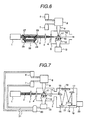
- FIG. 6 A third embodiment of the invention will be described with reference to Fig. 6.
- This is an example of a laser beam plasma X-ray source using a fine particle mixture gas according to the invention in which laser beam 2 is irradiated by two different pulses having a difference in time of emission.
- a laser beam splitter delay optical system 26 As a means for producing and irradiating two pulses different in time sequence, a laser beam splitter delay optical system 26 is used.
- This laser beam splitter delay optical system 26 includes a beam splitter 27 which splits a laser beam from laser generator 1 into two parts, a mirror 28 which functions to lengthen an optical path of a splitted laser beam than that of non-splitted laser beam, and a beam mixer 29 which synthesizes two laser beams into one laser beam 2. Pulses of these two laser beams are caused to delay in times of irradiation from each other in proportion to a difference between their optical paths.
- a first pulse irradiated on fine particle mixture gas target 10 produces laser plasma 11. Then, a second pulse is used to heat laser plasma 11, thereby improving the efficiency of X-ray generation. Further, since fine particles having been unable fully to fission into atomic states by the first pulse are heated further by the second pulse so as to completely fission, occurrence of particle debris in the plasma producible region can be minimized.
- a fourth embodiment of the invention will be described with reference to Fig. 7.
- a separator 30 for separating between metal fine particles and rare gas is provided to the target recovery unit 113 of the first embodiment of the invention for returning separated fine particles and rare gas to the original particle tank 6 and gas cylinder 7 for recycling.
Landscapes
- Engineering & Computer Science (AREA)
- Physics & Mathematics (AREA)
- Plasma & Fusion (AREA)
- General Physics & Mathematics (AREA)
- Epidemiology (AREA)
- Public Health (AREA)
- Chemical & Material Sciences (AREA)
- Health & Medical Sciences (AREA)
- Nanotechnology (AREA)
- Life Sciences & Earth Sciences (AREA)
- Atmospheric Sciences (AREA)
- Optics & Photonics (AREA)
- Crystallography & Structural Chemistry (AREA)
- Mathematical Physics (AREA)
- Theoretical Computer Science (AREA)
- Environmental & Geological Engineering (AREA)
- X-Ray Techniques (AREA)
- Exposure And Positioning Against Photoresist Photosensitive Materials (AREA)
- Exposure Of Semiconductors, Excluding Electron Or Ion Beam Exposure (AREA)
- Plasma Technology (AREA)
Description
According to this embodiment, a cigar-type plasma is produced from which a higher intensity X-ray can be obtained in the axial direction of the plasma since more X-rays are emitted in this direction.
Claims (10)
- A laser plasma X-ray source (100) comprising:characterized bya vacuum chamber (5)a target injector (9) for injecting a target (10) containing a gas into said vacuum chamber (5); anda laser (120) for irradiating a laser beam (2) onto said target (10) in said vacuum chamber (5) for generating an X-ray producing plasma,
a mixer (8) for preparing a mixture of solid or liquid preformed particles with said gas as said target (10). - The X-ray source of claim 1, wherein
the constituting element of said solid or liquid.particles is different from the constituting element of said gas. - The X-ray source of claim 1 or 2, wherein
said gas is a rare gas, preferably Xe. - The X-ray source of any preceding claim, wherein
the constituting element of said solid or liquid particles is a metal having a low melting point, preferably Sn or Sb. - The X-ray source of any preceding claim, wherein
the wavelength of the characteristic X-ray of the constituting element of said solid or liquid particles is substantially the same as the wavelength of the characteristic X-ray of said rare gas. - The X-ray source of any preceding claim, wherein
said solid or liquid particles have a diameter which is smaller than the diameter of said laser beam (2). - The X-ray source of any preceding claim, further
comprising a recovery port (13) opposite to said target injector (9) for recovering said target (10); wherein said laser beam (2) is irradiated onto said target (10) between said target injector (9) and said recovery port (13). - The X-ray source according any preceding claim, wherein said laser (120) comprises a converging lens (3) which focuses said laser beam (2) onto a straight line which is transverse to the flow of said target (10).
- A semiconductor lithography apparatus comprising a laser plasma X-ray source (100) according to any of claims 1 to 8.
- A semiconductor lithography method using a laser plasma X-ray source (100) according to any of claims 1 to 8.
Applications Claiming Priority (3)
| Application Number | Priority Date | Filing Date | Title |
|---|---|---|---|
| JP24731/97 | 1997-02-07 | ||
| JP9024731A JPH10221499A (en) | 1997-02-07 | 1997-02-07 | Laser plasma X-ray source, semiconductor exposure apparatus and semiconductor exposure method using the same |
| JP2473197 | 1997-02-07 |
Publications (2)
| Publication Number | Publication Date |
|---|---|
| EP0858249A1 EP0858249A1 (en) | 1998-08-12 |
| EP0858249B1 true EP0858249B1 (en) | 2003-04-09 |
Family
ID=12146305
Family Applications (1)
| Application Number | Title | Priority Date | Filing Date |
|---|---|---|---|
| EP98101013A Expired - Lifetime EP0858249B1 (en) | 1997-02-07 | 1998-01-21 | Laser plasma X-ray source, semiconductor lithography apparatus and method using those devices |
Country Status (8)
| Country | Link |
|---|---|
| US (1) | US5991360A (en) |
| EP (1) | EP0858249B1 (en) |
| JP (1) | JPH10221499A (en) |
| KR (1) | KR19980071020A (en) |
| AU (1) | AU5273298A (en) |
| CA (1) | CA2229170C (en) |
| DE (1) | DE69813065T2 (en) |
| TW (1) | TW393662B (en) |
Cited By (1)
| Publication number | Priority date | Publication date | Assignee | Title |
|---|---|---|---|---|
| DE112010000850B4 (en) * | 2009-02-13 | 2017-04-06 | Kla-Tencor Corp. | Method and device for maintaining and generating a plasma |
Families Citing this family (111)
| Publication number | Priority date | Publication date | Assignee | Title |
|---|---|---|---|---|
| WO1999051355A1 (en) * | 1998-04-03 | 1999-10-14 | Advanced Energy Systems, Inc. | Diffuser system and energy emission system for photolithography |
| WO1999051356A1 (en) * | 1998-04-03 | 1999-10-14 | Advanced Energy Systems, Inc. | Fluid nozzle system, energy emission system for photolithography and its method of manufacture |
| US6065203A (en) * | 1998-04-03 | 2000-05-23 | Advanced Energy Systems, Inc. | Method of manufacturing very small diameter deep passages |
| JP2002510548A (en) * | 1998-04-03 | 2002-04-09 | アドヴァンスト エナジー システムズ インコーポレイテッド | Energy release system for photolithography |
| US6194733B1 (en) | 1998-04-03 | 2001-02-27 | Advanced Energy Systems, Inc. | Method and apparatus for adjustably supporting a light source for use in photolithography |
| US6105885A (en) | 1998-04-03 | 2000-08-22 | Advanced Energy Systems, Inc. | Fluid nozzle system and method in an emitted energy system for photolithography |
| WO1999063790A1 (en) * | 1998-05-29 | 1999-12-09 | Nikon Corporation | Laser-excited plasma light source, exposure apparatus and its manufacturing method, and device manufacturing method |
| US6324255B1 (en) | 1998-08-13 | 2001-11-27 | Nikon Technologies, Inc. | X-ray irradiation apparatus and x-ray exposure apparatus |
| WO2000019496A1 (en) * | 1998-09-28 | 2000-04-06 | Hitachi, Ltd. | Laser plasma x-ray generator, semiconductor aligner having the generator, and semiconductor exposure method |
| JP2000294523A (en) * | 1999-04-01 | 2000-10-20 | Sony Corp | Semiconductor manufacturing apparatus and semiconductor device manufacturing method |
| DE19905802A1 (en) * | 1999-02-12 | 2000-08-17 | Philips Corp Intellectual Pty | X-ray tube |
| DE19924204A1 (en) * | 1999-05-27 | 2000-11-30 | Geesthacht Gkss Forschung | Device and method for generating x-rays |
| JP2001108799A (en) * | 1999-10-08 | 2001-04-20 | Nikon Corp | X-ray generator, X-ray exposure apparatus, and method for manufacturing semiconductor device |
| US6831963B2 (en) * | 2000-10-20 | 2004-12-14 | University Of Central Florida | EUV, XUV, and X-Ray wavelength sources created from laser plasma produced from liquid metal solutions |
| US7492867B1 (en) * | 1999-10-11 | 2009-02-17 | University Of Central Flordia Research Foundation, Inc. | Nanoparticle seeded short-wavelength discharge lamps |
| US6377651B1 (en) * | 1999-10-11 | 2002-04-23 | University Of Central Florida | Laser plasma source for extreme ultraviolet lithography using a water droplet target |
| FR2799667B1 (en) | 1999-10-18 | 2002-03-08 | Commissariat Energie Atomique | METHOD AND DEVICE FOR GENERATING A DENSE FOG OF MICROMETRIC AND SUBMICROMETRIC DROPLETS, APPLICATION TO THE GENERATION OF LIGHT IN EXTREME ULTRAVIOLET IN PARTICULAR FOR LITHOGRAPHY |
| AU1241401A (en) * | 1999-10-27 | 2001-05-08 | Jmar Research, Inc. | Method and radiation generating system using microtargets |
| TW502559B (en) * | 1999-12-24 | 2002-09-11 | Koninkl Philips Electronics Nv | Method of generating extremely short-wave radiation, method of manufacturing a device by means of said radiation, extremely short-wave radiation source unit and lithographic projection apparatus provided with such a radiation source unit |
| US6304630B1 (en) * | 1999-12-24 | 2001-10-16 | U.S. Philips Corporation | Method of generating EUV radiation, method of manufacturing a device by means of said radiation, EUV radiation source unit, and lithographic projection apparatus provided with such a radiation source unit |
| US6320937B1 (en) * | 2000-04-24 | 2001-11-20 | Takayasu Mochizuki | Method and apparatus for continuously generating laser plasma X-rays by the use of a cryogenic target |
| US6972421B2 (en) * | 2000-06-09 | 2005-12-06 | Cymer, Inc. | Extreme ultraviolet light source |
| EP1305984B1 (en) * | 2000-07-28 | 2010-11-24 | Jettec AB | Method and apparatus for generating x-ray radiation |
| EP1182510B1 (en) * | 2000-08-25 | 2006-04-12 | ASML Netherlands B.V. | Lithographic projection apparatus |
| US6956885B2 (en) | 2000-08-31 | 2005-10-18 | Powerlase Limited | Electromagnetic radiation generation using a laser produced plasma |
| TW548524B (en) * | 2000-09-04 | 2003-08-21 | Asm Lithography Bv | Lithographic projection apparatus, device manufacturing method and device manufactured thereby |
| US6693989B2 (en) * | 2000-09-14 | 2004-02-17 | The Board Of Trustees Of The University Of Illinois | Ultrabright multikilovolt x-ray source: saturated amplification on noble gas transition arrays from hollow atom states |
| US6614505B2 (en) | 2001-01-10 | 2003-09-02 | Asml Netherlands B.V. | Lithographic projection apparatus, device manufacturing method, and device manufactured thereby |
| EP1223468B1 (en) * | 2001-01-10 | 2008-07-02 | ASML Netherlands B.V. | Lithographic projection apparatus and device manufacturing method |
| FR2823949A1 (en) * | 2001-04-18 | 2002-10-25 | Commissariat Energie Atomique | METHOD AND DEVICE FOR GENERATING LIGHT IN THE EXTREME ULTRAVIOLET, ESPECIALLY FOR LITHOGRAPHY |
| US7476886B2 (en) * | 2006-08-25 | 2009-01-13 | Cymer, Inc. | Source material collection unit for a laser produced plasma EUV light source |
| GB0111204D0 (en) | 2001-05-08 | 2001-06-27 | Mertek Ltd | High flux,high energy photon source |
| JP4995379B2 (en) * | 2001-06-18 | 2012-08-08 | ギガフォトン株式会社 | Light source device and exposure apparatus using the same |
| FR2826893B1 (en) * | 2001-07-05 | 2003-09-19 | Snecma Moteurs | MINIATURIZED LASER BEAM WELDING APPARATUS |
| DE10147454A1 (en) * | 2001-09-20 | 2003-04-17 | Univ Schiller Jena | Target collector for removing liquid targets unused during the generation of plasma for emitting extreme UV electromagnetic radiation collects the liquid targets from an evacuated interactive chamber. |
| DE10149654A1 (en) * | 2001-10-08 | 2003-04-10 | Univ Schiller Jena | Synchronizing target time sequence and laser stimulation pulses incident on them for plasma emission stimulation involves controling target and/or pulse generation with target sensor signal |
| DE10205189B4 (en) * | 2002-02-06 | 2012-06-28 | Xtreme Technologies Gmbh | Method for producing extreme ultraviolet radiation based on a radiation-emitting plasma |
| DE10215469B4 (en) * | 2002-04-05 | 2005-03-17 | Xtreme Technologies Gmbh | Arrangement for suppression of particle emission in the case of radiation generation based on hot plasma |
| JP4111487B2 (en) | 2002-04-05 | 2008-07-02 | ギガフォトン株式会社 | Extreme ultraviolet light source device |
| US7239686B2 (en) * | 2002-05-13 | 2007-07-03 | Jettec Ab | Method and arrangement for producing radiation |
| DE10251435B3 (en) * | 2002-10-30 | 2004-05-27 | Xtreme Technologies Gmbh | Radiation source for extreme UV radiation for photolithographic exposure applications for semiconductor chip manufacture |
| US6770895B2 (en) | 2002-11-21 | 2004-08-03 | Asml Holding N.V. | Method and apparatus for isolating light source gas from main chamber gas in a lithography tool |
| TWI255394B (en) | 2002-12-23 | 2006-05-21 | Asml Netherlands Bv | Lithographic apparatus with debris suppression means and device manufacturing method |
| EP1434095A1 (en) * | 2002-12-23 | 2004-06-30 | ASML Netherlands B.V. | Lithographic apparatus and device manufacturing method |
| EP1606980B1 (en) * | 2003-03-18 | 2010-08-04 | Philips Intellectual Property & Standards GmbH | Device for and method of generating extreme ultraviolet and/or soft x-ray radiation by means of a plasma |
| US6919573B2 (en) | 2003-03-20 | 2005-07-19 | Asml Holding N.V | Method and apparatus for recycling gases used in a lithography tool |
| DE10326279A1 (en) * | 2003-06-11 | 2005-01-05 | MAX-PLANCK-Gesellschaft zur Förderung der Wissenschaften e.V. | Plasma-based generation of X-radiation with a layered target material |
| US6973164B2 (en) * | 2003-06-26 | 2005-12-06 | University Of Central Florida Research Foundation, Inc. | Laser-produced plasma EUV light source with pre-pulse enhancement |
| EP1491963A3 (en) * | 2003-06-27 | 2005-08-17 | ASML Netherlands B.V. | Laser produced plasma radiation system with contamination barrier |
| US7034308B2 (en) * | 2003-06-27 | 2006-04-25 | Asml Netherlands B.V. | Radiation system, contamination barrier, lithographic apparatus, device manufacturing method and device manufactured thereby |
| DE10337667B4 (en) * | 2003-08-12 | 2012-03-22 | Xtreme Technologies Gmbh | Plasma radiation source and arrangement for generating a gas curtain for plasma radiation sources |
| FR2860385B1 (en) * | 2003-09-26 | 2007-06-01 | Cit Alcatel | SOURCE EUV |
| US7061574B2 (en) | 2003-11-11 | 2006-06-13 | Asml Netherlands B.V. | Lithographic apparatus with contamination suppression, device manufacturing method, and device manufactured thereby |
| US7135692B2 (en) * | 2003-12-04 | 2006-11-14 | Asml Netherlands B.V. | Lithographic apparatus, illumination system and method for providing a projection beam of EUV radiation |
| GB0403865D0 (en) * | 2004-02-20 | 2004-03-24 | Powerlase Ltd | Laser multiplexing |
| US7078717B2 (en) * | 2004-03-22 | 2006-07-18 | Gigaphoton Inc. | Light source device and exposure equipment using the same |
| US20050213710A1 (en) * | 2004-03-29 | 2005-09-29 | Lawrence Brian L | System and method for laser X-ray generation |
| US20050211910A1 (en) * | 2004-03-29 | 2005-09-29 | Jmar Research, Inc. | Morphology and Spectroscopy of Nanoscale Regions using X-Rays Generated by Laser Produced Plasma |
| JP4763684B2 (en) * | 2004-03-31 | 2011-08-31 | コーニンクレッカ フィリップス エレクトロニクス エヌ ヴィ | Removal of particles produced by radiation sources |
| JP4696478B2 (en) * | 2004-06-09 | 2011-06-08 | 株式会社Ihi | Plasma X-ray generator |
| DE102004028943B4 (en) * | 2004-06-11 | 2006-10-12 | Xtreme Technologies Gmbh | Device for stable generation of EUV radiation by means of a laser-induced plasma |
| KR100583768B1 (en) * | 2004-07-07 | 2006-05-26 | 한국과학기술원 | Particle Beam Focusing Device Using Light Pressure |
| US7302043B2 (en) * | 2004-07-27 | 2007-11-27 | Gatan, Inc. | Rotating shutter for laser-produced plasma debris mitigation |
| US7466796B2 (en) * | 2004-08-05 | 2008-12-16 | Gatan, Inc. | Condenser zone plate illumination for point X-ray sources |
| US7452820B2 (en) * | 2004-08-05 | 2008-11-18 | Gatan, Inc. | Radiation-resistant zone plates and method of manufacturing thereof |
| JP4578901B2 (en) * | 2004-09-09 | 2010-11-10 | 株式会社小松製作所 | Extreme ultraviolet light source device |
| JP4517147B2 (en) * | 2004-11-26 | 2010-08-04 | 国立大学法人 宮崎大学 | Extreme ultraviolet light source device |
| JP4565194B2 (en) * | 2004-12-17 | 2010-10-20 | 国立大学法人大阪大学 | Extreme ultraviolet light / X-ray source target and manufacturing method thereof |
| WO2006075535A1 (en) | 2005-01-12 | 2006-07-20 | Nikon Corporation | Laser plasma euv light source, target member, production method for target member, target supplying method, and euv exposure system |
| JP4710463B2 (en) * | 2005-07-21 | 2011-06-29 | ウシオ電機株式会社 | Extreme ultraviolet light generator |
| JP4599342B2 (en) * | 2005-12-27 | 2010-12-15 | エーエスエムエル ネザーランズ ビー.ブイ. | Optical apparatus, lithographic apparatus, and device manufacturing method |
| DE102006017904B4 (en) | 2006-04-13 | 2008-07-03 | Xtreme Technologies Gmbh | Arrangement for generating extreme ultraviolet radiation from an energy beam generated plasma with high conversion efficiency and minimal contamination |
| US8766212B2 (en) * | 2006-07-19 | 2014-07-01 | Asml Netherlands B.V. | Correction of spatial instability of an EUV source by laser beam steering |
| JP5108367B2 (en) * | 2007-04-27 | 2012-12-26 | ギガフォトン株式会社 | Extreme ultraviolet light source device |
| JP5388018B2 (en) * | 2007-05-07 | 2014-01-15 | 独立行政法人日本原子力研究開発機構 | Laser-driven compact, high-contrast, coherent X-ray generator and generation method thereof |
| JP2009070982A (en) * | 2007-09-12 | 2009-04-02 | Nikon Corp | Scattered particle removal apparatus, scattered particle reduction method, light source apparatus, illumination optical apparatus, exposure apparatus, and electronic device manufacturing method |
| JP4389991B2 (en) * | 2007-10-26 | 2009-12-24 | ソニー株式会社 | Method and apparatus for optical measurement of fine particles |
| US8084757B2 (en) * | 2008-01-17 | 2011-12-27 | Applied Materials, Inc. | Contamination prevention in extreme ultraviolet lithography |
| JP5304097B2 (en) * | 2008-08-18 | 2013-10-02 | 凸版印刷株式会社 | Reflective photomask, gripping apparatus, and exposure apparatus |
| EP2743963B8 (en) * | 2009-04-03 | 2015-10-28 | Excillum AB | Supply of a liquid-metal target in x-ray generation |
| CN104681378B (en) * | 2009-04-03 | 2017-04-12 | 伊克斯拉姆公司 | Liquid metal target supply during x-ray production |
| JPWO2010137625A1 (en) | 2009-05-27 | 2012-11-15 | ギガフォトン株式会社 | Target output device and extreme ultraviolet light source device |
| JP2011023712A (en) | 2009-06-19 | 2011-02-03 | Gigaphoton Inc | Euv light source device |
| JP2011192965A (en) | 2010-02-22 | 2011-09-29 | Komatsu Ltd | Chamber apparatus and extreme ultraviolet light generating device |
| US9072152B2 (en) | 2010-03-29 | 2015-06-30 | Gigaphoton Inc. | Extreme ultraviolet light generation system utilizing a variation value formula for the intensity |
| US9072153B2 (en) | 2010-03-29 | 2015-06-30 | Gigaphoton Inc. | Extreme ultraviolet light generation system utilizing a pre-pulse to create a diffused dome shaped target |
| JP5802410B2 (en) * | 2010-03-29 | 2015-10-28 | ギガフォトン株式会社 | Extreme ultraviolet light generator |
| JP5921876B2 (en) * | 2011-02-24 | 2016-05-24 | ギガフォトン株式会社 | Extreme ultraviolet light generator |
| TWI580316B (en) * | 2011-03-16 | 2017-04-21 | Gigaphoton Inc | Extreme UV light generation device |
| JP5921879B2 (en) | 2011-03-23 | 2016-05-24 | ギガフォトン株式会社 | Target supply device and extreme ultraviolet light generation device |
| JP5901210B2 (en) * | 2011-10-06 | 2016-04-06 | 浜松ホトニクス株式会社 | Radiation generation apparatus and radiation generation method |
| US9268031B2 (en) * | 2012-04-09 | 2016-02-23 | Kla-Tencor Corporation | Advanced debris mitigation of EUV light source |
| US10801975B2 (en) | 2012-05-08 | 2020-10-13 | Kla-Tencor Corporation | Metrology tool with combined X-ray and optical scatterometers |
| WO2013180007A1 (en) * | 2012-05-29 | 2013-12-05 | ギガフォトン株式会社 | Extreme uv light generation device and extreme uv light generation system |
| DE102012209837A1 (en) * | 2012-06-12 | 2013-12-12 | Trumpf Laser- Und Systemtechnik Gmbh | EUV excitation light source with a laser beam source and a beam guiding device for manipulating the laser beam |
| CN103209536A (en) * | 2013-03-22 | 2013-07-17 | 中国科学院上海光学精密机械研究所 | Method for producing soft X ray |
| US9609729B2 (en) * | 2013-04-19 | 2017-03-28 | Raytheon Company | X-ray cells and other components having gas cells with thermally-induced density gradients |
| US9506871B1 (en) | 2014-05-25 | 2016-11-29 | Kla-Tencor Corporation | Pulsed laser induced plasma light source |
| US9301381B1 (en) | 2014-09-12 | 2016-03-29 | International Business Machines Corporation | Dual pulse driven extreme ultraviolet (EUV) radiation source utilizing a droplet comprising a metal core with dual concentric shells of buffer gas |
| CN105828513B (en) * | 2016-03-28 | 2019-04-12 | 中国科学院近代物理研究所 | Target system and the system for generating neutron and/or neutrino with target system |
| CN105682335B (en) * | 2016-03-28 | 2019-09-27 | 中国科学院近代物理研究所 | Target system and system with target system for generating neutrons and/or neutrinos |
| EP3261110A1 (en) * | 2016-06-21 | 2017-12-27 | Excillum AB | X-ray source with ionisation tool |
| WO2018029759A1 (en) | 2016-08-08 | 2018-02-15 | ギガフォトン株式会社 | Extreme ultraviolet light generation method |
| US11330697B2 (en) * | 2016-12-27 | 2022-05-10 | Brown University | Modular laser-produced plasma X-ray system |
| JP7225224B2 (en) * | 2017-10-26 | 2023-02-20 | エーエスエムエル ネザーランズ ビー.ブイ. | System for monitoring plasma |
| US10959318B2 (en) * | 2018-01-10 | 2021-03-23 | Kla-Tencor Corporation | X-ray metrology system with broadband laser produced plasma illuminator |
| JP2021009274A (en) * | 2018-07-09 | 2021-01-28 | レーザーテック株式会社 | Light source, inspection device, EUV light generation method and inspection method |
| EP3726940A3 (en) * | 2019-04-16 | 2020-11-11 | Okinawa Institute of Science and Technology School Corporation | Laser-driven microplasma xuv source |
| US11259394B2 (en) * | 2019-11-01 | 2022-02-22 | Kla Corporation | Laser produced plasma illuminator with liquid sheet jet target |
| JP6885636B1 (en) * | 2020-03-05 | 2021-06-16 | アールアンドディー−イーサン,リミテッド | Laser-excited plasma light source and plasma ignition method |
| US11882642B2 (en) | 2021-12-29 | 2024-01-23 | Innovicum Technology Ab | Particle based X-ray source |
Family Cites Families (18)
| Publication number | Priority date | Publication date | Assignee | Title |
|---|---|---|---|---|
| US4538291A (en) * | 1981-11-09 | 1985-08-27 | Kabushiki Kaisha Suwa Seikosha | X-ray source |
| DE3586244T2 (en) * | 1984-12-26 | 2000-04-20 | Kabushiki Kaisha Toshiba | Device for generating soft X-rays by means of a high-energy bundle. |
| JP2614457B2 (en) * | 1986-09-11 | 1997-05-28 | ホーヤ 株式会社 | Laser plasma X-ray generator and X-ray exit opening / closing mechanism |
| JPS63254150A (en) * | 1987-04-10 | 1988-10-20 | Meidensha Electric Mfg Co Ltd | Electrically conductive plastic for electrode |
| JPH02100297A (en) * | 1988-10-07 | 1990-04-12 | Mitsubishi Electric Corp | Generation method for x-ray of laser excitation type |
| US4953191A (en) * | 1989-07-24 | 1990-08-28 | The United States Of America As Represented By The United States Department Of Energy | High intensity x-ray source using liquid gallium target |
| JPH03201399A (en) * | 1989-12-27 | 1991-09-03 | Shimadzu Corp | Method of generating x-ray |
| JPH05258692A (en) * | 1992-03-10 | 1993-10-08 | Nikon Corp | X-ray generating method and x-ray generating device |
| US5487078A (en) * | 1994-03-14 | 1996-01-23 | Board Of Trustees Of The University Of Illinois | Apparatus and method for generating prompt x-radiation from gas clusters |
| US5459771A (en) * | 1994-04-01 | 1995-10-17 | University Of Central Florida | Water laser plasma x-ray point source and apparatus |
| US5577091A (en) * | 1994-04-01 | 1996-11-19 | University Of Central Florida | Water laser plasma x-ray point sources |
| JP2552433B2 (en) * | 1994-06-30 | 1996-11-13 | 関西電力株式会社 | Method and apparatus for removing debris from laser plasma X-ray source |
| JPH08138594A (en) * | 1994-11-11 | 1996-05-31 | Olympus Optical Co Ltd | Soft x-ray source device |
| US5577092A (en) * | 1995-01-25 | 1996-11-19 | Kublak; Glenn D. | Cluster beam targets for laser plasma extreme ultraviolet and soft x-ray sources |
| JPH08236292A (en) * | 1995-02-27 | 1996-09-13 | Hitachi Ltd | Laser plasma X-ray generator |
| JP3666056B2 (en) * | 1995-05-30 | 2005-06-29 | 株式会社ニコン | X-ray generator and X-ray lithography apparatus |
| JP3508079B2 (en) * | 1995-07-17 | 2004-03-22 | 日本原子力研究所 | Method of forming plasma micro-undulator |
| JPH1055899A (en) * | 1996-08-08 | 1998-02-24 | Nikon Corp | X-ray generator |
-
1997
- 1997-02-07 JP JP9024731A patent/JPH10221499A/en active Pending
- 1997-12-20 TW TW086119460A patent/TW393662B/en not_active IP Right Cessation
-
1998
- 1998-01-21 EP EP98101013A patent/EP0858249B1/en not_active Expired - Lifetime
- 1998-01-21 DE DE69813065T patent/DE69813065T2/en not_active Expired - Fee Related
- 1998-01-23 AU AU52732/98A patent/AU5273298A/en not_active Abandoned
- 1998-02-03 KR KR1019980002877A patent/KR19980071020A/en not_active Ceased
- 1998-02-03 US US09/018,316 patent/US5991360A/en not_active Expired - Fee Related
- 1998-02-06 CA CA002229170A patent/CA2229170C/en not_active Expired - Fee Related
Cited By (1)
| Publication number | Priority date | Publication date | Assignee | Title |
|---|---|---|---|---|
| DE112010000850B4 (en) * | 2009-02-13 | 2017-04-06 | Kla-Tencor Corp. | Method and device for maintaining and generating a plasma |
Also Published As
| Publication number | Publication date |
|---|---|
| JPH10221499A (en) | 1998-08-21 |
| DE69813065D1 (en) | 2003-05-15 |
| AU5273298A (en) | 1998-08-13 |
| KR19980071020A (en) | 1998-10-26 |
| EP0858249A1 (en) | 1998-08-12 |
| DE69813065T2 (en) | 2004-03-04 |
| CA2229170A1 (en) | 1998-08-07 |
| CA2229170C (en) | 2001-09-11 |
| TW393662B (en) | 2000-06-11 |
| US5991360A (en) | 1999-11-23 |
Similar Documents
| Publication | Publication Date | Title |
|---|---|---|
| US5991360A (en) | Laser plasma x-ray source, semiconductor lithography apparatus using the same and a method thereof | |
| JP5454881B2 (en) | Extreme ultraviolet light source device and method for generating extreme ultraviolet light | |
| Ter-Avetisyan et al. | Quasimonoenergetic deuteron bursts produced by ultraintense laser pulses | |
| US7619232B2 (en) | Method and device for producing extreme ultraviolet radiation or soft X-ray radiation | |
| EP1460886B1 (en) | Extreme UV radiation source and semiconductor exposure device | |
| JP5073146B2 (en) | X-ray generation method and apparatus | |
| US6711233B2 (en) | Method and apparatus for generating X-ray or EUV radiation | |
| US5637962A (en) | Plasma wake field XUV radiation source | |
| JP5183928B2 (en) | Methods and apparatus for generating EUV radiation and / or soft X-ray radiation in particular | |
| JP2003534631A (en) | Extreme ultraviolet source based on controlling neutral beam | |
| US7557511B2 (en) | Apparatus and method utilizing high power density electron beam for generating pulsed stream of ablation plasma | |
| KR20130138313A (en) | Methods and system for controlled fusion reactions | |
| US20110089834A1 (en) | Z-pinch plasma generator and plasma target | |
| JP3433151B2 (en) | Laser plasma X-ray source | |
| N. Chichkov et al. | Soft-X-ray lasers with charge transfer pumping in a mixture of clusters and atomic gases | |
| Borghesi et al. | Propagation issues and energetic particle production in laser–plasma interactions at intensities exceeding 1019 W/cm2 | |
| TWI393486B (en) | Method and apparatus for generating radiation in the wavelength range of from about 1 nanometer to about 30 nanometers and use in a lithography device or in a metrology | |
| SU1463051A1 (en) | Source of ion beams | |
| JPH03201399A (en) | Method of generating x-ray | |
| Belchenko et al. | Studies of surface-plasma negative ion sources at Novosibirsk | |
| Bazhenov et al. | Influence of carrier migration processes on threshold characteristics of semiconductor lasers pumped longitudinally by an electron beam | |
| JPWO2000019496A1 (en) | Laser plasma X-ray generator, and semiconductor exposure apparatus and semiconductor exposure method using the same | |
| Scholz et al. | 6 Research outside the Euratom fusion programme | |
| Badziak et al. | Fast Ions From Picosecond Laser-Plasma Interaction |
Legal Events
| Date | Code | Title | Description |
|---|---|---|---|
| PUAI | Public reference made under article 153(3) epc to a published international application that has entered the european phase |
Free format text: ORIGINAL CODE: 0009012 |
|
| AK | Designated contracting states |
Kind code of ref document: A1 Designated state(s): DE FR GB |
|
| AX | Request for extension of the european patent |
Free format text: AL;LT;LV;MK;RO;SI |
|
| 17P | Request for examination filed |
Effective date: 19980715 |
|
| AKX | Designation fees paid |
Free format text: DE FR GB |
|
| RBV | Designated contracting states (corrected) |
Designated state(s): DE FR GB |
|
| 17Q | First examination report despatched |
Effective date: 20010613 |
|
| RTI1 | Title (correction) |
Free format text: LASER PLASMA X-RAY SOURCE, SEMICONDUCTOR LITHOGRAPHY APPARATUS AND METHOD USING THOSE DEVICES |
|
| GRAH | Despatch of communication of intention to grant a patent |
Free format text: ORIGINAL CODE: EPIDOS IGRA |
|
| RTI1 | Title (correction) |
Free format text: LASER PLASMA X-RAY SOURCE, SEMICONDUCTOR LITHOGRAPHY APPARATUS AND METHOD USING THOSE DEVICES |
|
| GRAH | Despatch of communication of intention to grant a patent |
Free format text: ORIGINAL CODE: EPIDOS IGRA |
|
| GRAA | (expected) grant |
Free format text: ORIGINAL CODE: 0009210 |
|
| AK | Designated contracting states |
Designated state(s): DE FR GB |
|
| REG | Reference to a national code |
Ref country code: GB Ref legal event code: FG4D |
|
| ET | Fr: translation filed | ||
| PLBE | No opposition filed within time limit |
Free format text: ORIGINAL CODE: 0009261 |
|
| STAA | Information on the status of an ep patent application or granted ep patent |
Free format text: STATUS: NO OPPOSITION FILED WITHIN TIME LIMIT |
|
| 26N | No opposition filed |
Effective date: 20040112 |
|
| PGFP | Annual fee paid to national office [announced via postgrant information from national office to epo] |
Ref country code: FR Payment date: 20041227 Year of fee payment: 8 |
|
| PGFP | Annual fee paid to national office [announced via postgrant information from national office to epo] |
Ref country code: GB Payment date: 20041231 Year of fee payment: 8 |
|
| PGFP | Annual fee paid to national office [announced via postgrant information from national office to epo] |
Ref country code: DE Payment date: 20050304 Year of fee payment: 8 |
|
| PG25 | Lapsed in a contracting state [announced via postgrant information from national office to epo] |
Ref country code: GB Free format text: LAPSE BECAUSE OF NON-PAYMENT OF DUE FEES Effective date: 20060121 |
|
| PG25 | Lapsed in a contracting state [announced via postgrant information from national office to epo] |
Ref country code: FR Free format text: LAPSE BECAUSE OF NON-PAYMENT OF DUE FEES Effective date: 20060131 |
|
| PG25 | Lapsed in a contracting state [announced via postgrant information from national office to epo] |
Ref country code: DE Free format text: LAPSE BECAUSE OF NON-PAYMENT OF DUE FEES Effective date: 20060801 |
|
| GBPC | Gb: european patent ceased through non-payment of renewal fee |
Effective date: 20060121 |
|
| REG | Reference to a national code |
Ref country code: FR Ref legal event code: ST Effective date: 20060929 |