EP0857899A2 - Shift inhibition for automated transmission - Google Patents
Shift inhibition for automated transmission Download PDFInfo
- Publication number
- EP0857899A2 EP0857899A2 EP98300839A EP98300839A EP0857899A2 EP 0857899 A2 EP0857899 A2 EP 0857899A2 EP 98300839 A EP98300839 A EP 98300839A EP 98300839 A EP98300839 A EP 98300839A EP 0857899 A2 EP0857899 A2 EP 0857899A2
- Authority
- EP
- European Patent Office
- Prior art keywords
- splitter
- transmission
- section
- auxiliary section
- actuator
- Prior art date
- Legal status (The legal status is an assumption and is not a legal conclusion. Google has not performed a legal analysis and makes no representation as to the accuracy of the status listed.)
- Granted
Links
Images


Classifications
-
- F—MECHANICAL ENGINEERING; LIGHTING; HEATING; WEAPONS; BLASTING
- F16—ENGINEERING ELEMENTS AND UNITS; GENERAL MEASURES FOR PRODUCING AND MAINTAINING EFFECTIVE FUNCTIONING OF MACHINES OR INSTALLATIONS; THERMAL INSULATION IN GENERAL
- F16H—GEARING
- F16H61/00—Control functions within control units of change-speed- or reversing-gearings for conveying rotary motion ; Control of exclusively fluid gearing, friction gearing, gearings with endless flexible members or other particular types of gearing
- F16H61/16—Inhibiting or initiating shift during unfavourable conditions, e.g. preventing forward reverse shift at high vehicle speed, preventing engine over speed
-
- F—MECHANICAL ENGINEERING; LIGHTING; HEATING; WEAPONS; BLASTING
- F16—ENGINEERING ELEMENTS AND UNITS; GENERAL MEASURES FOR PRODUCING AND MAINTAINING EFFECTIVE FUNCTIONING OF MACHINES OR INSTALLATIONS; THERMAL INSULATION IN GENERAL
- F16H—GEARING
- F16H61/00—Control functions within control units of change-speed- or reversing-gearings for conveying rotary motion ; Control of exclusively fluid gearing, friction gearing, gearings with endless flexible members or other particular types of gearing
- F16H61/02—Control functions within control units of change-speed- or reversing-gearings for conveying rotary motion ; Control of exclusively fluid gearing, friction gearing, gearings with endless flexible members or other particular types of gearing characterised by the signals used
- F16H61/0202—Control functions within control units of change-speed- or reversing-gearings for conveying rotary motion ; Control of exclusively fluid gearing, friction gearing, gearings with endless flexible members or other particular types of gearing characterised by the signals used the signals being electric
- F16H61/0248—Control units where shifting is directly initiated by the driver, e.g. semi-automatic transmissions
-
- F—MECHANICAL ENGINEERING; LIGHTING; HEATING; WEAPONS; BLASTING
- F16—ENGINEERING ELEMENTS AND UNITS; GENERAL MEASURES FOR PRODUCING AND MAINTAINING EFFECTIVE FUNCTIONING OF MACHINES OR INSTALLATIONS; THERMAL INSULATION IN GENERAL
- F16H—GEARING
- F16H61/00—Control functions within control units of change-speed- or reversing-gearings for conveying rotary motion ; Control of exclusively fluid gearing, friction gearing, gearings with endless flexible members or other particular types of gearing
- F16H61/21—Providing engine brake control
-
- F—MECHANICAL ENGINEERING; LIGHTING; HEATING; WEAPONS; BLASTING
- F16—ENGINEERING ELEMENTS AND UNITS; GENERAL MEASURES FOR PRODUCING AND MAINTAINING EFFECTIVE FUNCTIONING OF MACHINES OR INSTALLATIONS; THERMAL INSULATION IN GENERAL
- F16H—GEARING
- F16H61/00—Control functions within control units of change-speed- or reversing-gearings for conveying rotary motion ; Control of exclusively fluid gearing, friction gearing, gearings with endless flexible members or other particular types of gearing
- F16H61/70—Control functions within control units of change-speed- or reversing-gearings for conveying rotary motion ; Control of exclusively fluid gearing, friction gearing, gearings with endless flexible members or other particular types of gearing specially adapted for change-speed gearing in group arrangement, i.e. with separate change-speed gear trains arranged in series, e.g. range or overdrive-type gearing arrangements
-
- F—MECHANICAL ENGINEERING; LIGHTING; HEATING; WEAPONS; BLASTING
- F16—ENGINEERING ELEMENTS AND UNITS; GENERAL MEASURES FOR PRODUCING AND MAINTAINING EFFECTIVE FUNCTIONING OF MACHINES OR INSTALLATIONS; THERMAL INSULATION IN GENERAL
- F16H—GEARING
- F16H63/00—Control outputs from the control unit to change-speed- or reversing-gearings for conveying rotary motion or to other devices than the final output mechanism
- F16H63/40—Control outputs from the control unit to change-speed- or reversing-gearings for conveying rotary motion or to other devices than the final output mechanism comprising signals other than signals for actuating the final output mechanisms
- F16H63/44—Signals to the control unit of auxiliary gearing
-
- Y—GENERAL TAGGING OF NEW TECHNOLOGICAL DEVELOPMENTS; GENERAL TAGGING OF CROSS-SECTIONAL TECHNOLOGIES SPANNING OVER SEVERAL SECTIONS OF THE IPC; TECHNICAL SUBJECTS COVERED BY FORMER USPC CROSS-REFERENCE ART COLLECTIONS [XRACs] AND DIGESTS
- Y10—TECHNICAL SUBJECTS COVERED BY FORMER USPC
- Y10S—TECHNICAL SUBJECTS COVERED BY FORMER USPC CROSS-REFERENCE ART COLLECTIONS [XRACs] AND DIGESTS
- Y10S477/00—Interrelated power delivery controls, including engine control
- Y10S477/906—Means detecting or ameliorating the effects of malfunction or potential malfunction
-
- Y—GENERAL TAGGING OF NEW TECHNOLOGICAL DEVELOPMENTS; GENERAL TAGGING OF CROSS-SECTIONAL TECHNOLOGIES SPANNING OVER SEVERAL SECTIONS OF THE IPC; TECHNICAL SUBJECTS COVERED BY FORMER USPC CROSS-REFERENCE ART COLLECTIONS [XRACs] AND DIGESTS
- Y10—TECHNICAL SUBJECTS COVERED BY FORMER USPC
- Y10T—TECHNICAL SUBJECTS COVERED BY FORMER US CLASSIFICATION
- Y10T74/00—Machine element or mechanism
- Y10T74/19—Gearing
- Y10T74/19219—Interchangeably locked
- Y10T74/19251—Control mechanism
- Y10T74/19256—Automatic
- Y10T74/1926—Speed responsive
Definitions
- the present invention relates to a vehicular, at least partially automated mechanical transmission system and a power-down control routine therefor.
- the present invention relates to an at least partially automated splitter-type mechanical transmission system having automatic splitter shifting in at least certain main section ratios and to a power-down control routine therefor.
- a new and improved power-down control routine for at least semi-automated mechanical transmissions having automatic splitter shifting in at least some ratios is provided.
- the foregoing is accomplished by providing a vehicular semi-automated mechanical transmission control system/method which is effective, when the vehicle operator causes a power-down by turning the ignition control to an off position, to retain the splitter section engaged in the then engaged ratio until vehicle speed is below a reference value or the main transmission section is shifted to neutral.
- the foregoing power-down control will minimize the occurrence of an unintended splitter section neutral condition under conditions when engine braking may be desirable.
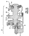
- Figures 1 and 1A are sectional views of a typical splitter or combined splitter and range-type compound transmission.
- Figure 2 is a schematic illustration of the manual shift pattern and ratio steps for the transmission of Figures 1 and 1A.
- Figure 3 is a schematic illustration of a partially automated vehicular mechanical transmission system having both manual and automatic splitter shifting and utilizing the control of the present invention.
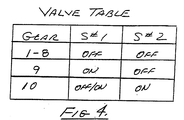
- Figure 4 is a valve table for the control valve assembly utilized in the system of Figure 3.
- Figure 5 is a schematic illustration, similar to Figure 2, of the shift pattern and ratio steps for the transmission system of Figure 3.
- Figure 6 is a graphical representation of the disengagement confirmation logic of the system of Figure 3.
- FIG. 7 is a schematic illustration of the control logic of the present invention.
- FIGS 1, 1A and 2 illustrate a typical combined splitter and range-type compound mechanical transmission 10 of the type advantageously utilized in connection with the control of the present invention.
- Transmission 10 comprises a main transmission section 12 connected in series with an auxiliary transmission section 14 having both range and splitter-type gearing.
- transmission 10 is housed within a single multi-piece housing 16 and includes an input shaft 18 driven by a prime mover (such as a diesel engine) through a selectively disengaged, normally engaged friction master clutch.
- a prime mover such as a diesel engine
- the input shaft 18 carries an input gear 20 for driving at least one countershaft assembly 22.
- input gear 20 simultaneously drives a plurality of substantially identical main section countershaft assemblies at substantially identical rotational speeds.
- Each of the main section countershaft assemblies comprises a main section countershaft 24 supported by bearings 26 and 28 in housing 16 and is provided with main section countershaft gears 30, 32, 34, 36 and 38 fixed thereto.
- a plurality of main section drive or main shaft gears 40, 42 and 44 surround the transmission main shaft 46 and are selectively clutchable, one at a time, to the main shaft 46 for rotation therewith by sliding clutch collars 48 and 50, as is well known in the art.
- Clutch collar 48 may also be utilized to clutch input gear 20 to the main shaft 46 to provide a direct drive relationship between the input shaft 18 and the main shaft 46.
- each of the main section main shaft gears encircles the main shaft 46 and is in continuous meshing engagement with and is floatingly supported by the associated countershaft gear groups, which mounting means and special advantages resulting therefrom are explained in greater detail in aforementioned U.S. Patents No. 3,105,395 and 3,335,616.
- clutch collars 48 and 50 are axially positioned by means of shift forks or yokes 52 and 54, respectively, associated with a shift bar housing assembly 56 of the type illustrated in U.S. Patents No. 4,920,815 and 5,000,060.
- Clutch collars 48 and 50 are, in the preferred embodiment, of the well-known, non-synchronized, double-acting jaw clutch type.
- Main section main shaft gear 44 is the reverse gear and is in continuous meshing engagement with countershaft gears 38 by means of conventional intermediate idler gears 57 (see Figure 1A).
- Main section countershaft gear 32 is provided for powering power takeoff devices and the like.
- Jaw clutches 48 and 50 are 3-position clutches in that they may be positioned in a centered axially non-displaced, non-engaged position as illustrated or in a fully rightwardly engaged or fully leftwardly engaged position.
- Auxiliary transmission section 14 is connected in series with main transmission section 12 and is of the 3-layer, 4-speed combined splitter/range type, as illustrated in above-mentioned U.S. Patent No. 4,754,665.
- Main shaft 46 extends into the auxiliary section 14 and is journaled in the inward end of the output shaft 58 which extends from the rearward end of the transmission.
- Auxiliary transmission section 14 includes, in the preferred embodiment thereof, a plurality of substantially identical auxiliary countershaft assemblies 60 (see Figure 1A), each comprising an auxiliary countershaft 62 supported by bearings 64 and 66 in housing 16 and carrying three auxiliary section countershaft gears 68, 70 and 72 fixed for rotation therewith.
- Auxiliary countershaft gears 68 are constantly meshed with and support auxiliary section splitter gear 74.
- Auxiliary countershaft gears 70 are constantly meshed with and support auxiliary section splitter/range gear 76 which surrounds the output shaft 58 at the end thereof adjacent the coaxial inner end of main shaft 46.
- Auxiliary section countershaft gears 72 constantly mesh with and support auxiliary section range gear 78, which surrounds the output shaft 58.
- auxiliary section countershaft gears 68 and splitter gear 74 define a first gear layer
- auxiliary section countershaft gears 70 and splitter/range gear 76 define a second gear layer
- auxiliary section countershaft gears 72 and range gear 78 define a third layer, or gear group, of the combined splitter and range-type auxiliary transmission section 14.
- a sliding 2-position jaw clutch collar 80 is utilized to selectively couple either the splitter gear 74 or the splitter/range gear 76 to the main shaft 46, while a 2-position synchronized clutch assembly 82 is utilized to selectively couple the splitter/range gear 76 or the range gear 78 to the output shaft 58.
- the splitter jaw clutch 80 is a 2-position clutch assembly which may be selectively positioned in the rightwardmost or leftwardmost positions for engaging either gear 76 or gear 74, respectively, to the main shaft 46.
- Splitter jaw clutch 80 is axially positioned by means of a shift fork 84 controlled by a 2-position piston actuator 86, which normally is operable by a driver selection switch such as a button or the like on the shift knob, as is known in the prior art.
- Two-position synchronized range clutch assembly 82 is also a 2-position clutch which may be selectively positioned in either the rightwardmost or leftwardmost positions thereof for selectively clutching either gear 78 or 76, respectively, to output shaft 58.
- Clutch assembly 82 is positioned by means of a shift fork 88 operated by means of a 2-position piston device 90, the actuation and control of which is described in greater detail in aforementioned U.S. Patent No. 4,974,468.
- auxiliary transmission section 14 is a 3-layer auxiliary section of the combined range and splitter type providing four selectable speeds or drive ratios between the input (main shaft 46) and output (output shaft 58) thereof.
- the main section 12 provides a reverse and three potentially selectable forward speeds.
- one of the selectable main section forward gear ratios, the low speed gear ratios associated with main shaft gear 42, is not utilized in the high range.
- transmission 10 is properly designated as a "(2+1)x(2x2)" type transmission providing nine or ten selectable forward speeds, depending upon the desirability and practicality of splitting the low gear ratio.
- clutch 82 (the range clutch) should be a synchronized clutch
- double-acting clutch collar 80 (the splitter clutch) is not required to be synchronized.
- the shift pattern for manually shifting transmission 10 is schematically illustrated in Figure 2. Divisions in the vertical direction at each gear lever position signify splitter shifts, while movement in the horizontal direction from the 3/4 and 5/6 leg of the H pattern to the 7/8 and 9/10 leg of the H pattern signifies a shift from the low range to the high range of the transmission.
- a partially automated vehicular mechanical transmission system 92 utilizing the control system of the present invention is illustrated in Figure 3.
- Partially automated system 92 is of the type requiring manual shifting in the lower gear ratios (first through eighth) and, after initial manual selection of one of the upper two ratios, providing automatic shifting in the upper gear ratios (ninth and tenth), as described in aforementioned U.S. Patents No. 4,722,248; 4,850,236; 5,038,027 and 5,393,276.
- the shift pattern for partially automated operation of the system 92 is schematically illustrated in Figure 5.
- the system includes a splitter control valve assembly 94 and a prime mover (such as diesel engine 96) driving the input shaft 18 of transmission 10 through a master friction clutch 98.
- the transmission 10 includes a shift lever 100 having a shift knob 102, which is associated with the shift bar housing 56 for manually shifting main section 12 and the range clutch 82 of auxiliary section 14.
- a manually operated splitter valve 104 having a selector lever or button 106, is provided, usually on or integral with the shift knob, for manually shifting the splitter clutch 80.
- Splitter valve 104 is a 2-position, 3-way manually operated valve effective to selectively connect a first pilot conduit 108 to exhaust (AE X A) or to pilot pressure, respectively, to manually select either the high or low splitter ratio.
- the pilot pressure may be equal to supply pressure ("S") or to a lower value. In a typical onboard pneumatic system, supply is filtered, regulated air at about 60 to 80 psi.
- the first pilot conduit 108 may fluidly communicate with a second pilot conduit 110 in series through the control valve assembly 94 of the present invention.
- the second pilot conduit 110 is effective to act on a 2-position, 3-way pilot valve 112, which is effective to normally vent or selectively pressurize a control chamber 114 of the splitter piston/cylinder actuator assembly 86.
- Chamber 114 is exposed to the larger area face 116 of a differential area piston 118 having a smaller area face 120 constantly exposed to supply pressure in biasing chamber 122.
- a spring may be utilized in place of or in combination with smaller area piston face 120 to bias piston 118 rightwardly, as seen in Figure 3.
- pilot valve 112 when pilot conduit 110 is exhausted, pilot valve 112 will connect control chamber 114 to exhaust, and supply pressure acting on smaller area face 120 will cause shift fork 84 to move splitter clutch 80 to engage gear 76 for the low splitter ratio, and when pilot conduit 110 is pressurized, valve 112 will move against a bias to a position for pressurizing control chamber 114, causing the piston 118 to move leftwardly to cause splitter clutch 80 to engage gear 74 for the high splitter ratio.
- a controller 124 preferably a microprocessor-based controller, is provided for receiving input signals 126 and for processing same according to predetermined logic rules to issue command output signals 128 to various system actuators, such as an engine fuel control 130 and a solenoid driver and fault detection unit 132. Controllers of this type may be seen by reference to U.S. Patents No. 4,361,060 and 4,595,986.
- the program for controller 124 is stored on a computer-usable medium such as a floppy disk, hard drive, CD-rom, tape or other external or internal storage medium.
- Sensors for sensing engine speed (ES) and/or input shaft speed (IS) and output shaft speed (OS) may be provided, as well as sensors for sensing engine fueling THL and solenoid faults SF, all of which provide input signals indicative thereof to the controller 124. With the clutch 98 engaged, input shaft speed may be assumed to equal engine speed.
- the engine 96 may have a built-in controller 96A and/or may communicate with controller 124 by an electronic data link of the type conforming to SAE J-1922, SAE J-1939, ISO 11898 or the like. All or a portion of controller 124 may be defined by hardware and/or software associated with engine controller 96A.
- the control valve assembly 94 of the present invention is interposed in series between the standard manual splitter shift selection valve 104 and the standard pilot valve 112/splitter actuator 86 and is operated in response to command output signals from controller 124.
- the assembly includes, in series, a first 2-position, 3-way solenoid-controlled valve 134 and a second 2-position, 3-way solenoid-controlled valve 136 and a solenoid driver and fault detection unit 132 operating in response to command output signals from the controller.
- Valve 134 has an inlet 138 connected to pilot conduit 108 and two outlets 140 (connected to one inlet 142 of valve 136) and 144 (connected to exhaust). Valve 134 has a first normal or default position wherein inlet 138 is connected to outlet 140, and thus, to inlet 142 of valve 136, while outlet 144 of valve 134 is blocked. Valve 134 has a second or actuated position upon energizing the first solenoid S#1 wherein outlet 140 is connected to exhaust at outlet 144 and inlet 138 is blocked.
- Valve 136 has two inlets 142 (connected to the outlet 140 of valve 134) and 146 (connected to the source of pressurized fluid) and an outlet 148 connected to the second pilot conduit 110 controlling the pilot valve 112.
- Valve 136 has a first normal or default position wherein inlet 142 is connected to outlet 148 and the inlet 146 from source pressure is blocked, and a second actuated position upon energizing the second solenoid S#2 wherein inlet 142 is blocked and source pressure at inlet 146 communicates with outlet 148 and pilot conduit 110.
- valve table for operation of the solenoid-operated valves is set forth in Figure 4.
- the controller 124 senses a manual splitter operation mode by sensing a shift bar condition GR other than AUTO (see Figure 5). In this mode (i.e. , gear ratios 1-8), the solenoid driver is commanded to deenergize both of the solenoids, and the valves 134 and 136 will assume the default positions thereof. Pilot conduit 108 will communicate with pilot conduit 110 through the valves 134 and 136, and the actuator 86 will be under the manual control of selector valve 104.
- AUTO or not-AUTO mode conditions may be sensed by position sensors or by processing the ES and OS signals according to predetermined logic rules.
- the controller Upon sensing a manual shift to the AUTO position, the controller will cause the solenoid driver 132 to energize the first solenoid S#1 to create an automatic-only splitter situation, as valve 134 moves to its second position, wherein the pilot conduit 108 controlled by manual selector valve 104 is blocked at inlet 138, and thus, the series connection through port 140 to the pilot valve 112 is blocked. With valve 134 in the second or actuated position thereof, the manual selector 104 is ineffective to control pilot valve 112 or splitter actuator 86.
- ninth and tenth speeds are the AUTO mode gear ratios, while eighth speed is the "entry gear ratio”.
- eighth speed is the "entry gear ratio”.
- the first reference value (REF 1 ) is an output shaft speed at which a manual upshift from the entry gear is expected to occur, usually about the minimum output shaft speed at which an upshift from the entry gear is expected to occur.
- valve 134 When in the AUTO mode of operation, manual control 104 is bypassed and, based upon vehicle speed as indicated by the output shaft speed OS and/or the other sensed parameters, the control 124 will automatically determine if an automatic upshift from ninth to tenth or an automatic downshift from tenth to ninth is required, and will control engine fueling and the second solenoid-controlled valve 136 to implement same.
- pilot conduit 110 With valve 134 actuated and valve 136 in its normal or default position, pilot conduit 110 is exhausted at port 144 of valve 134, and pilot valve 112 will exhaust the control chamber 114 of the piston/cylinder assembly 86, causing the piston to urge the splitter clutch in the low splitter ratio direction.
- pilot conduit 110 is connected to source pressure through inlet 146 and outlet 148 of valve 136, regardless of the position of valve 134, and pilot valve 112 will cause control chamber 114 to be pressurized, causing the piston 118 to urge the splitter clutch in the high splitter ratio direction.
- Valve 134 may be deactivated whenever valve 136 is energized to reduce heat generation.
- controller 124 will also cause the engine to be properly fueled to disengage the existing splitter ratio and synchronized for engaging the target splitter ratio.
- controller 124 Upon sensing an eighth-to-ninth upshift into AUTO mode, the engine will be caused to synchronize for the required main and splitter clutch engagement.
- the controller 124 Upon sensing that a shift from AUTO mode has occurred, the controller 124 will cause solenoid driver 132 to deactivate both solenoids to return splitter control to the operator.
- solenoid driver 132 Upon sensing that a shift from AUTO mode has occurred, the controller 124 will cause solenoid driver 132 to deactivate both solenoids to return splitter control to the operator.
- a not-AUTO mode condition is confirmed when either:
- the first, immediately preceding example involves a downshift out of AUTO mode, while the second example involves an apparent operator shift to main section neutral during an AUTO mode shift event.
- ES/OS GR*(1 ⁇ Y%)
- a given percent Y such as 0.5 to 1.5%.
- the quotient of ES/OS is compared to the numerical value of the disengaging gear, plus or minus a disengaging gear error value, which may exceed the magnitude of the gear error value used to confirm engagement.
- the disengaging gear error value may equal 1.5%
- the engaging gear error value may equal 1%.
- the gear error value used for confirming disengagement may be set larger on the positive side of synchronous of the disengaging gear than on the negative side to minimize false indications of neutral.
- Speed separations while still in gear tend to be higher on the positive side of synchronous due to the higher driving torque (the engine driving the vehicle tends to produce a greater positive torque magnitude than the negative torque produced when coasting with the vehicle driving the engine).
- Providing a larger Pos_Disengage_Gear_Error and a smaller Neg_Disengage_Gear_Error allows for protection against false indications of neutral on the positive side caused by aggressive throttle application, while still providing for a quick confirmation of neutral in the negative direction (the direction in which neutral is confirmed on most shifts).
- the calculated gear ratio is compared to an expanding window of error values and will be confirmed as disengaged only if it continues to remain outside the window.
- the calculated gear ratio must fall outside a range from: [Engaged GR*(1-(40*Counter*Loop_Time*Neg_Disengage_Gear_Error))] to [Engaged GR*(1+(40*Counter*Loop_Time*Pos_Disengage_Gear_Error))], where Counter is incremented by one each time this is true and decremented each time this is not true (minimizing at a value of 1).
- This "expanding window” over a fixed error band is that it allows disengagement confirmation to start sooner (using the relatively small initial error window) while simultaneously providing better protection against false confirmations of neutral (using the relatively large, fully expanded window before confirming). If the calculated gear ratios fall back within the window during the disengagement confirmation process, the window will decrement to the next smaller value (or to the smallest window) and upon the calculated gear ratio falling outside the window, the disengagement process will continue.
- the advantage gained with this "contracting window” over immediately resetting to the smallest error window is that it maintains a quick confirmation of true disengagement even if one data point falls inside the expanding error bounds, while preventing false neutral confirmation with transient speed separations induced by large torque oscillations.
- the solenoid-controlled valves Upon an electrical power failure, the solenoid-controlled valves will return to the open positions thereof, fluidly connecting conduits 108 and 110, and allowing manual selection of all ten forward ratios.
- the solenoid driver Upon the solenoid driver detecting conditions indicative of a failure at one or both solenoids, the controller will cause both solenoids to be de-energized again, causing the two valves 134 and 136 to assume the open positions thereof, and allow manual selection of all ten forward ratios.
- the control valve assembly 94 thus, provides a control allowing both manual and automatic splitter shifting, provides a favorable failure mode and as a module requires only four additional fluid connections (conduit 108 to port 138, conduit 110 to port 148, source S to port 146 and exhaust E X to port 144) to the normally utilized manual splitter control.
- an operator-actuated ignition switch 170 is provided, allowing the vehicle operator to select power-on or power-off vehicle operating conditions.
- the ignition switch typically requires a key or code for operation thereof and provides a signal to the ECU.
- splitter shift may be initiated unless the solenoid-controlled valves 134 and/or 136 are maintained as are. If such a splitter shift is allowed to initiate under certain power-down conditions, the shift may not be completed, which may result in an unintended and/or undesirable transmission neutral condition.
- engine braking may not be utilized to retard the vehicle.
- the ECU logic rules will cause the solenoid driver 132 to maintain the solenoids S1 and/or S2 in their current conditions until either (i) vehicle speed becomes less than a reference value (OS ⁇ REF) and/or (ii) the transmission main section 12 is shifted into neutral.
- OS ⁇ REF reference value
- the transmission main section 12 is shifted into neutral.
- engine braking is less critical and a shift into main section neutral increases the probability of completing a splitter section shift and/or indicates that a transmission neutral condition is acceptable.
- main section ratio positions will include the 1/2, 2/3, 3/4, 5/6, 7/8 and 9/10(A) ratio positions, and the range section is considered a portion of the manually shifted main section.
Abstract
Description
Serial No. 08/439,908
- Filed:
- 12/05/95
- Title
- AUTOMATIC AND MANUAL SPLITTER SHIFTING CONTROL VALVE ASSEMBLY
- Filed:
- 30/04/96
- Title:
- SYNCHRONIZING AND GEAR ENGAGEMENT SENSING LOGIC FOR AUTOMATED MECHANICAL TRANSMISSION SYSTEMS
- Filed:
- 30/04/96
- Title:
- SEMI-AUTOMATED SHIFT IMPLEMENTATION WITH AUTOMATIC SPLITTER SHIFTING
- Filed:
- 05/02/97
- Title:
- SENSING MANUAL SHIFT INTO AUTOMATED UPPER RATIOS
- Filed:
- 05/02/97
- Title:
- AUTOMODE TO NEUTRAL LOGIC
- Filed:
- 05/02/97
- Title:
- ANTI-HUNT LOGIC
- Filed:
- 05/02/97
- Title:
- DISENGAGEMENT CONFIRMATION
- Filed:
- 05/02/97
- Title:
- ENGAGEMENT OF GEAR RATIO CONFIRMATION
- Filed:
- 05/02/97
- Title:
- TRANSITION TO DEGRADED MODE OF OPERATION
- (1) vehicle speed exceeds the first reference value, and
- (2) gear ratio is one of the AUTO mode ratios.
an AUTO mode shift (ninth-tenth, tenth-ninth) is in progress.
- (1) an AUTO shift is in progress, and
- (2) after a given period of time, engagement in an AUTO mode ratio cannot be confirmed;
engagement in a non-AUTO mode ratio is confirmed.
[Engaged GR*(1-(40*Counter*Loop_Time*Neg_Disengage_Gear_Error))] to
[Engaged GR*(1+(40*Counter*Loop_Time*Pos_Disengage_Gear_Error))],
where Counter is incremented by one each time this is true and decremented each time this is not true (minimizing at a value of 1). Disengagement is confirmed when the Counter reaches or exceeds a value equal to (Synch_Disengage_Time/Loop_Time). In the preferred embodiment, the values of Neg_Disengage_Gear_Error = 1%, Pos_Disengage_Gear_Error = 1.5%, and the maximum value of (40*Counter*Loop_Time) = 6.
Claims (9)
- A splitter-type automated mechanical transmission system including a mechanical transmission having a main section connected in series with a splitter-type auxiliary section, an electronic control unit for receiving input signals including signals indicative of engaged gear ratio, vehicle speed and system power-down conditions, and for processing same according to predetermined logic rules to issue command output signals to system actuators including an actuator for causing automatic shifting of said splitter section, said system characterized by:
said controller including logic effective upon initiation of a system power-down to prevent automatic shifting of said splitter section until at least one of (a) vehicle speed falling below a reference value or (b) a shift into main section neutral is sensed. - The system of claim 1 wherein said reference value is less than 15 MPH.
- The system of claim 1 wherein said reference value is less than 10 MPH.
- The system of claim 1 additionally comprising an operator-actuated ignition switch for manual selection of system power-up and power-down conditions.
- A partially automated vehicular transmission system comprising a compound transmission having a main section and a two-speed auxiliary section, an auxiliary section shift actuator having first and second positions for engaging first and second auxiliary section ratios, respectively, a controller for receiving input signals indicative of system operating conditions and for processing same in accordance with logic rules to issue command output signals to system actuators including a control assembly actuator, a first conduit having a first and a second state, a manually controlled selector for selectively causing said first conduit to have said first and second states, a second conduit having a first and a second state, said shift actuator responsive to said second conduit being in said first state to move to said first position thereof and responsive to said second conduit being in said second state to move to said second position thereof, a control assembly interposed in series between said first and second conduits, said control assembly controlled by said control assembly actuator and having a first condition for establishing communication between said first and second conduits, and a second condition for blocking communication between said first and second conduits and selectively causing said second conduit to have said first and second states independent of said manual selector, said controller including logic rules, effective at system power-down, to cause said control assembly not to change from said second to said first condition unless at least one of (a) vehicle speed becomes less than a reference value and (b) main section neutral is sensed.
- The transmission system of claim 5 wherein said rules include rules for sensing selection of a manual auxiliary section shifting mode and of an automatic auxiliary section shifting mode.
- A partially automated vehicular transmission system comprising a compound transmission having a main section, a two-speed auxiliary section, an auxiliary section shift actuator having first and second positions for engaging first and second auxiliary section ratios, respectively, a manually controlled selector having first and second states, a controller for receiving input signals indicative of system operating conditions and for processing same in accordance with logic rules, including logic rules for sensing selection of a manual auxiliary section shifting mode and of an automatic auxiliary section shifting mode, to issue command output signals to system actuators including a control assembly actuator, a control assembly interposed in series between said selector and controlled by said control assembly actuator and having a first condition wherein said shift actuator will assume said first position thereof in response to said selector being in said first state and said second position thereof in response to said selector being in said second state, and a second condition for causing said shift actuator to assume a selected one of said first and second positions thereof independent of the state of said selector, said controller including logic rules, effective at system power-down, to cause said actuator not to change from said second to said first condition unless at least one of (a) vehicle speed becomes less than a reference value and (b) main section neutral is sensed.
- The system of claim 7 wherein selection of said automatic auxiliary section shifting mode requires one of engagement, disengagement or operation in one of the top two (ninth and tenth) transmission ratios.
- A semi-automatic mechanical transmission system comprising a shift control system and a splitter-type compound vehicular transmission having a main section connected in series with an auxiliary section including splitter gearing, said transmission having a plurality of groups of forward gear ratios, with each of said groups (i) being manually selectable by an operator, (ii) corresponding to a particular transmission main section ratio, and (iii) including a plurality of sequentially related splitter gear ratios, said transmission including actuator means enabling automatic splitter shifting between the sequentially related gear ratios within at least one of said groups, and said control system operable to command the actuator means to effect automatic splitter shifting between the sequentially related gear ratios within at least one of said groups when at least one of said groups is manually selected by the operator, said system characterized by said control system including logic rules effective at system power-down to retain said splitter section in its then-engaged condition until at least one of (a) vehicle speed becomes less than a reference value and (b) main section neutral is sensed.
Applications Claiming Priority (2)
| Application Number | Priority Date | Filing Date | Title |
|---|---|---|---|
| US795918 | 1997-02-05 | ||
| US08/795,918 US5964121A (en) | 1997-02-05 | 1997-02-05 | Automated transmission system power-down |
Publications (3)
| Publication Number | Publication Date |
|---|---|
| EP0857899A2 true EP0857899A2 (en) | 1998-08-12 |
| EP0857899A3 EP0857899A3 (en) | 1999-04-07 |
| EP0857899B1 EP0857899B1 (en) | 2002-10-16 |
Family
ID=25166783
Family Applications (1)
| Application Number | Title | Priority Date | Filing Date |
|---|---|---|---|
| EP98300839A Expired - Lifetime EP0857899B1 (en) | 1997-02-05 | 1998-02-05 | Shift inhibition for automated transmission |
Country Status (5)
| Country | Link |
|---|---|
| US (1) | US5964121A (en) |
| EP (1) | EP0857899B1 (en) |
| CN (1) | CN1108247C (en) |
| BR (1) | BR9800420A (en) |
| DE (1) | DE69808679T2 (en) |
Cited By (2)
| Publication number | Priority date | Publication date | Assignee | Title |
|---|---|---|---|---|
| WO2009097993A1 (en) * | 2008-02-05 | 2009-08-13 | Daimler Ag | Gearbox guard device |
| WO2012056222A3 (en) * | 2010-10-26 | 2012-11-01 | Protean Electric Limited | Hybrid vehicle |
Families Citing this family (8)
| Publication number | Priority date | Publication date | Assignee | Title |
|---|---|---|---|---|
| JP3443342B2 (en) * | 1998-11-19 | 2003-09-02 | 三菱電機株式会社 | Electronically controlled automatic transmission |
| EP1092894B1 (en) | 1999-10-12 | 2007-01-03 | Eaton Corporation | Control for engaging start ratios in controller-assisted, manually shifted, splitter-type compound transmissions |
| US6257082B1 (en) * | 2000-03-13 | 2001-07-10 | Eaton Corporation | Auxiliary section control for manual transmission |
| DE10150316A1 (en) * | 2000-10-23 | 2002-05-29 | Luk Lamellen & Kupplungsbau | Protection against rolling for motor vehicles fitted with an automatic transmission, uses fixed sequence of starting and gear engagement to ensure gearbox is in determinate state at starting |
| FR2844273B1 (en) * | 2002-09-05 | 2008-04-04 | Aventis Pharma Sa | NOVEL HETEROCYCLIC COMPOUNDS, METHOD AND INTERMEDIARY PREPARATION AND USE AS MEDICAMENT, IN PARTICULAR AS INHIBITORS OF BETA-LACTAMASES AND ANTI-BACTERIALS. |
| EP3559508B1 (en) | 2016-12-22 | 2023-07-12 | Eaton Cummins Automated Transmission Technologies, LLC | High efficiency, high output transmission |
| US10584778B2 (en) | 2016-12-22 | 2020-03-10 | Eaton Cummins Automated Transmission Technologies, Llc | High efficiency, high output transmission |
| JP6733561B2 (en) * | 2017-01-17 | 2020-08-05 | トヨタ自動車株式会社 | Vehicle shift control device |
Citations (27)
| Publication number | Priority date | Publication date | Assignee | Title |
|---|---|---|---|---|
| US3105395A (en) | 1962-12-26 | 1963-10-01 | Eaton Mfg Co | Automotive device |
| US3335616A (en) | 1966-01-20 | 1967-08-15 | Eaton Yale & Towne | Twin countershaft with fixed main shaft |
| US3429202A (en) | 1965-08-19 | 1969-02-25 | Georges Camille Eugene Galiche | Gear boxes |
| US3799002A (en) | 1972-07-31 | 1974-03-26 | Eaton Corp | Transmission with resiliently loaded main shaft gears |
| US4361060A (en) | 1978-01-24 | 1982-11-30 | Smyth Robert Ralston | Mechanical automatic transmission |
| US4455883A (en) | 1980-11-14 | 1984-06-26 | Eaton Corporation | Combined shift control |
| US4561325A (en) | 1983-10-20 | 1985-12-31 | Dana Corporation | Transmission and range box control |
| US4595986A (en) | 1984-10-09 | 1986-06-17 | Eaton Corporation | Method for control of automatic mechanical transmission system utilizing a microprocessor based electronic controller |
| US4663725A (en) | 1985-02-15 | 1987-05-05 | Thermo King Corporation | Microprocessor based control system and method providing better performance and better operation of a shipping container refrigeration system |
| US4722248A (en) | 1986-04-11 | 1988-02-02 | Eaton Corporation | Transmission shift control system |
| US4754665A (en) | 1986-02-05 | 1988-07-05 | Eaton Corporation | Auxiliary transmission section |
| US4850236A (en) | 1987-11-20 | 1989-07-25 | Eaton Corporation | Vehicle drive line shift control system and method |
| US4920815A (en) | 1989-04-24 | 1990-05-01 | Eaton Corporation | Single shaft shifting mechanism |
| US4974468A (en) | 1989-02-16 | 1990-12-04 | Eaton Corporation | Compound transmission and shift control therefor |
| US5000060A (en) | 1989-02-16 | 1991-03-19 | Reynolds Joseph D | Compound transmission and shift control therefor |
| US5038027A (en) | 1989-04-19 | 1991-08-06 | Mitsubishi Denki Kabushiki Kaisha | Contact reading image sensor with a rod lens array |
| US5038627A (en) | 1990-04-25 | 1991-08-13 | Dana Corporation | Vehicle transmission with manually shifted lower gears and automatically shifted upper gears |
| US5193410A (en) | 1992-01-23 | 1993-03-16 | Eaton Corporation | Range section protection valve assembly |
| US5329826A (en) | 1992-01-22 | 1994-07-19 | Eaton Corporation | Enhanced automated splitter shifting with dual solenoid valves and auto fuel control |
| US5370013A (en) | 1993-05-20 | 1994-12-06 | Eaton Corporation | Helically geared compound transmission |
| US5390561A (en) | 1993-05-20 | 1995-02-21 | Eaton Corporation | Compound transmission |
| US5393276A (en) | 1993-10-12 | 1995-02-28 | Cummins Electronics Company, Inc. | Method and apparatus for control of engine compression brakes before, during and after an electronically controlled gear shift |
| US5393277A (en) | 1993-10-12 | 1995-02-28 | Cummins Electronics Company, Inc. | Variable electronically controlled shift points for a cruise control system |
| US5435212A (en) | 1992-10-30 | 1995-07-25 | Eaton Corporation | Semi-automatic shift implementation |
| US5498195A (en) | 1994-11-10 | 1996-03-12 | Cummins Electronics Company, Inc. | Apparatus and method for verifying gear engagement in controlling the automatic shifting of a manual-automatic transmission |
| EP0742393A2 (en) | 1995-05-12 | 1996-11-13 | Eaton Corporation | Automatic and manual splitter shifting control assembly |
| US5682790A (en) | 1996-04-30 | 1997-11-04 | Eaton Corporation | Synchronizing and gear engagement sensing logic for automated mechanical transmission system |
Family Cites Families (12)
| Publication number | Priority date | Publication date | Assignee | Title |
|---|---|---|---|---|
| US4167126A (en) * | 1977-08-15 | 1979-09-11 | Hixon William K | Control system for vehicle overdrive transmission |
| US4551802A (en) * | 1982-11-17 | 1985-11-05 | Eaton Corporation | Automatic transmission control method |
| US4722237A (en) * | 1986-12-12 | 1988-02-02 | Eaton Corporation | Fluid actuated shift bar housing assembly having a centering cylinder therein |
| US4742731A (en) * | 1986-12-18 | 1988-05-10 | Payhauler Corp. | Transmission range selector valve |
| US5089965A (en) * | 1989-07-24 | 1992-02-18 | Eaton Corporation | Shift prohibiting for automatic shift preselection mode for mechanical transmission system with semi-automatic shift implementation |
| US5044216A (en) * | 1990-08-30 | 1991-09-03 | Eaton Corporation | Transmission shift control |
| US5105675A (en) * | 1991-06-03 | 1992-04-21 | Ford New Holland, Inc. | Creeper gear engagement/disengagement |
| US5401223A (en) * | 1993-08-18 | 1995-03-28 | Cummins Electronics Company, Inc. | Method and device for controlling critical switch failure and neutral conditions at high and low vehicle speeds |
| US5591102A (en) * | 1995-06-07 | 1997-01-07 | Cummins Engine Company, Inc. | Apparatus and method for controlling a manual-automatic transmission after a power reset |
| US5682792A (en) * | 1996-06-28 | 1997-11-04 | Caterpillar Inc. | Dependent latching system for a transmission |
| US5682791A (en) * | 1996-06-28 | 1997-11-04 | Caterpillar Inc. | Independent latching system for a transmission |
| US5875409A (en) * | 1997-02-05 | 1999-02-23 | Eaton Corporation | Transition to degraded mode of operation |
-
1997
- 1997-02-05 US US08/795,918 patent/US5964121A/en not_active Expired - Lifetime
-
1998
- 1998-02-04 BR BR9800420A patent/BR9800420A/en not_active Application Discontinuation
- 1998-02-05 EP EP98300839A patent/EP0857899B1/en not_active Expired - Lifetime
- 1998-02-05 CN CN98104118A patent/CN1108247C/en not_active Expired - Fee Related
- 1998-02-05 DE DE69808679T patent/DE69808679T2/en not_active Expired - Fee Related
Patent Citations (27)
| Publication number | Priority date | Publication date | Assignee | Title |
|---|---|---|---|---|
| US3105395A (en) | 1962-12-26 | 1963-10-01 | Eaton Mfg Co | Automotive device |
| US3429202A (en) | 1965-08-19 | 1969-02-25 | Georges Camille Eugene Galiche | Gear boxes |
| US3335616A (en) | 1966-01-20 | 1967-08-15 | Eaton Yale & Towne | Twin countershaft with fixed main shaft |
| US3799002A (en) | 1972-07-31 | 1974-03-26 | Eaton Corp | Transmission with resiliently loaded main shaft gears |
| US4361060A (en) | 1978-01-24 | 1982-11-30 | Smyth Robert Ralston | Mechanical automatic transmission |
| US4455883A (en) | 1980-11-14 | 1984-06-26 | Eaton Corporation | Combined shift control |
| US4561325A (en) | 1983-10-20 | 1985-12-31 | Dana Corporation | Transmission and range box control |
| US4595986A (en) | 1984-10-09 | 1986-06-17 | Eaton Corporation | Method for control of automatic mechanical transmission system utilizing a microprocessor based electronic controller |
| US4663725A (en) | 1985-02-15 | 1987-05-05 | Thermo King Corporation | Microprocessor based control system and method providing better performance and better operation of a shipping container refrigeration system |
| US4754665A (en) | 1986-02-05 | 1988-07-05 | Eaton Corporation | Auxiliary transmission section |
| US4722248A (en) | 1986-04-11 | 1988-02-02 | Eaton Corporation | Transmission shift control system |
| US4850236A (en) | 1987-11-20 | 1989-07-25 | Eaton Corporation | Vehicle drive line shift control system and method |
| US4974468A (en) | 1989-02-16 | 1990-12-04 | Eaton Corporation | Compound transmission and shift control therefor |
| US5000060A (en) | 1989-02-16 | 1991-03-19 | Reynolds Joseph D | Compound transmission and shift control therefor |
| US5038027A (en) | 1989-04-19 | 1991-08-06 | Mitsubishi Denki Kabushiki Kaisha | Contact reading image sensor with a rod lens array |
| US4920815A (en) | 1989-04-24 | 1990-05-01 | Eaton Corporation | Single shaft shifting mechanism |
| US5038627A (en) | 1990-04-25 | 1991-08-13 | Dana Corporation | Vehicle transmission with manually shifted lower gears and automatically shifted upper gears |
| US5329826A (en) | 1992-01-22 | 1994-07-19 | Eaton Corporation | Enhanced automated splitter shifting with dual solenoid valves and auto fuel control |
| US5193410A (en) | 1992-01-23 | 1993-03-16 | Eaton Corporation | Range section protection valve assembly |
| US5435212A (en) | 1992-10-30 | 1995-07-25 | Eaton Corporation | Semi-automatic shift implementation |
| US5370013A (en) | 1993-05-20 | 1994-12-06 | Eaton Corporation | Helically geared compound transmission |
| US5390561A (en) | 1993-05-20 | 1995-02-21 | Eaton Corporation | Compound transmission |
| US5393276A (en) | 1993-10-12 | 1995-02-28 | Cummins Electronics Company, Inc. | Method and apparatus for control of engine compression brakes before, during and after an electronically controlled gear shift |
| US5393277A (en) | 1993-10-12 | 1995-02-28 | Cummins Electronics Company, Inc. | Variable electronically controlled shift points for a cruise control system |
| US5498195A (en) | 1994-11-10 | 1996-03-12 | Cummins Electronics Company, Inc. | Apparatus and method for verifying gear engagement in controlling the automatic shifting of a manual-automatic transmission |
| EP0742393A2 (en) | 1995-05-12 | 1996-11-13 | Eaton Corporation | Automatic and manual splitter shifting control assembly |
| US5682790A (en) | 1996-04-30 | 1997-11-04 | Eaton Corporation | Synchronizing and gear engagement sensing logic for automated mechanical transmission system |
Cited By (2)
| Publication number | Priority date | Publication date | Assignee | Title |
|---|---|---|---|---|
| WO2009097993A1 (en) * | 2008-02-05 | 2009-08-13 | Daimler Ag | Gearbox guard device |
| WO2012056222A3 (en) * | 2010-10-26 | 2012-11-01 | Protean Electric Limited | Hybrid vehicle |
Also Published As
| Publication number | Publication date |
|---|---|
| DE69808679D1 (en) | 2002-11-21 |
| DE69808679T2 (en) | 2003-07-03 |
| CN1195083A (en) | 1998-10-07 |
| CN1108247C (en) | 2003-05-14 |
| EP0857899A3 (en) | 1999-04-07 |
| US5964121A (en) | 1999-10-12 |
| EP0857899B1 (en) | 2002-10-16 |
| BR9800420A (en) | 1999-08-10 |
| MX9801018A (en) | 1998-12-31 |
Similar Documents
| Publication | Publication Date | Title |
|---|---|---|
| EP0857604B1 (en) | Splitter shift controller and engine fuel controller | |
| EP0857896B1 (en) | Engagement of gear ratio confirmation | |
| EP0805062B1 (en) | Synchronizing and gear engagement sensing logic for automated mechanical transmission system | |
| US5735771A (en) | Semi-automatic shift implementation | |
| US5755639A (en) | Semi-automatic shift implementation with automatic splitter shifting | |
| EP0512707B1 (en) | Range shifting only fault tolerance method/system | |
| US5761628A (en) | Start gear ratio control system and method utilizing the highest allowable start gear ratio | |
| EP0857898B1 (en) | Anti-hunt logic | |
| EP0742393B1 (en) | Automatic and manual splitter shifting control assembly | |
| EP0688977A2 (en) | Engagement fault degraded mode control for transmissions | |
| EP0857894B1 (en) | Sensing manual shift into automated upper ratios | |
| US5964121A (en) | Automated transmission system power-down | |
| EP0688978B1 (en) | Splitter section engagement control | |
| EP0857897B1 (en) | Operation mode transition of an automated transmission | |
| EP0857895B1 (en) | Disengagement confirmation | |
| EP0863039A1 (en) | Semi-automatic shift implementation with automatic engine control enable switch | |
| US5992256A (en) | Control to suspend automatic upper ratio shifting | |
| MXPA98001018A (en) | . t stop energy automatic transmission system | |
| MXPA98001019A (en) | Detection of manual change to superior relations automation | |
| MXPA98001014A (en) | Transition to degrad operation mode | |
| MXPA98001013A (en) | Logo from automodo to neut | |
| MXPA98001016A (en) | Confirmation of desvinculac | |
| MXPA98001015A (en) | Confirmation of engr relationship |
Legal Events
| Date | Code | Title | Description |
|---|---|---|---|
| PUAI | Public reference made under article 153(3) epc to a published international application that has entered the european phase |
Free format text: ORIGINAL CODE: 0009012 |
|
| AK | Designated contracting states |
Kind code of ref document: A2 Designated state(s): DE FR GB IT SE |
|
| AX | Request for extension of the european patent |
Free format text: AL;LT;LV;MK;RO;SI |
|
| PUAL | Search report despatched |
Free format text: ORIGINAL CODE: 0009013 |
|
| AK | Designated contracting states |
Kind code of ref document: A3 Designated state(s): AT BE CH DE DK ES FI FR GB GR IE IT LI LU MC NL PT SE |
|
| AX | Request for extension of the european patent |
Free format text: AL;LT;LV;MK;RO;SI |
|
| 17P | Request for examination filed |
Effective date: 19991006 |
|
| AKX | Designation fees paid |
Free format text: DE FR GB IT SE |
|
| 17Q | First examination report despatched |
Effective date: 20010720 |
|
| GRAG | Despatch of communication of intention to grant |
Free format text: ORIGINAL CODE: EPIDOS AGRA |
|
| GRAG | Despatch of communication of intention to grant |
Free format text: ORIGINAL CODE: EPIDOS AGRA |
|
| GRAH | Despatch of communication of intention to grant a patent |
Free format text: ORIGINAL CODE: EPIDOS IGRA |
|
| GRAH | Despatch of communication of intention to grant a patent |
Free format text: ORIGINAL CODE: EPIDOS IGRA |
|
| GRAA | (expected) grant |
Free format text: ORIGINAL CODE: 0009210 |
|
| AK | Designated contracting states |
Kind code of ref document: B1 Designated state(s): DE FR GB IT SE |
|
| REG | Reference to a national code |
Ref country code: GB Ref legal event code: FG4D |
|
| REF | Corresponds to: |
Ref document number: 69808679 Country of ref document: DE Date of ref document: 20021121 |
|
| ET | Fr: translation filed | ||
| PLBE | No opposition filed within time limit |
Free format text: ORIGINAL CODE: 0009261 |
|
| STAA | Information on the status of an ep patent application or granted ep patent |
Free format text: STATUS: NO OPPOSITION FILED WITHIN TIME LIMIT |
|
| 26N | No opposition filed |
Effective date: 20030717 |
|
| PGFP | Annual fee paid to national office [announced via postgrant information from national office to epo] |
Ref country code: FR Payment date: 20060202 Year of fee payment: 9 |
|
| PGFP | Annual fee paid to national office [announced via postgrant information from national office to epo] |
Ref country code: IT Payment date: 20060228 Year of fee payment: 9 |
|
| REG | Reference to a national code |
Ref country code: FR Ref legal event code: ST Effective date: 20071030 |
|
| PG25 | Lapsed in a contracting state [announced via postgrant information from national office to epo] |
Ref country code: FR Free format text: LAPSE BECAUSE OF NON-PAYMENT OF DUE FEES Effective date: 20070228 |
|
| PGFP | Annual fee paid to national office [announced via postgrant information from national office to epo] |
Ref country code: DE Payment date: 20090227 Year of fee payment: 12 |
|
| PGFP | Annual fee paid to national office [announced via postgrant information from national office to epo] |
Ref country code: GB Payment date: 20090106 Year of fee payment: 12 |
|
| PGFP | Annual fee paid to national office [announced via postgrant information from national office to epo] |
Ref country code: SE Payment date: 20090206 Year of fee payment: 12 |
|
| PG25 | Lapsed in a contracting state [announced via postgrant information from national office to epo] |
Ref country code: IT Free format text: LAPSE BECAUSE OF NON-PAYMENT OF DUE FEES Effective date: 20070205 |
|
| EUG | Se: european patent has lapsed | ||
| GBPC | Gb: european patent ceased through non-payment of renewal fee |
Effective date: 20100205 |
|
| PG25 | Lapsed in a contracting state [announced via postgrant information from national office to epo] |
Ref country code: DE Free format text: LAPSE BECAUSE OF NON-PAYMENT OF DUE FEES Effective date: 20100901 |
|
| PG25 | Lapsed in a contracting state [announced via postgrant information from national office to epo] |
Ref country code: GB Free format text: LAPSE BECAUSE OF NON-PAYMENT OF DUE FEES Effective date: 20100205 |
|
| PG25 | Lapsed in a contracting state [announced via postgrant information from national office to epo] |
Ref country code: SE Free format text: LAPSE BECAUSE OF NON-PAYMENT OF DUE FEES Effective date: 20100206 |