EP0857845B1 - Device for manual release of a gate from a respective powered actuator - Google Patents
Device for manual release of a gate from a respective powered actuator Download PDFInfo
- Publication number
- EP0857845B1 EP0857845B1 EP98200285A EP98200285A EP0857845B1 EP 0857845 B1 EP0857845 B1 EP 0857845B1 EP 98200285 A EP98200285 A EP 98200285A EP 98200285 A EP98200285 A EP 98200285A EP 0857845 B1 EP0857845 B1 EP 0857845B1
- Authority
- EP
- European Patent Office
- Prior art keywords
- bolt
- plate
- gate
- engagement
- accordance
- Prior art date
- Legal status (The legal status is an assumption and is not a legal conclusion. Google has not performed a legal analysis and makes no representation as to the accuracy of the status listed.)
- Expired - Lifetime
Links
- 230000007246 mechanism Effects 0.000 description 11
- 230000003993 interaction Effects 0.000 description 2
- 230000000295 complement effect Effects 0.000 description 1
- 238000004513 sizing Methods 0.000 description 1
- XLYOFNOQVPJJNP-UHFFFAOYSA-N water Substances O XLYOFNOQVPJJNP-UHFFFAOYSA-N 0.000 description 1
Images

Classifications
-
- E—FIXED CONSTRUCTIONS
- E05—LOCKS; KEYS; WINDOW OR DOOR FITTINGS; SAFES
- E05B—LOCKS; ACCESSORIES THEREFOR; HANDCUFFS
- E05B65/00—Locks or fastenings for special use
- E05B65/0007—Locks or fastenings for special use for gates
-
- E—FIXED CONSTRUCTIONS
- E05—LOCKS; KEYS; WINDOW OR DOOR FITTINGS; SAFES
- E05C—BOLTS OR FASTENING DEVICES FOR WINGS, SPECIALLY FOR DOORS OR WINDOWS
- E05C1/00—Fastening devices with bolts moving rectilinearly
- E05C1/08—Fastening devices with bolts moving rectilinearly with latching action
- E05C1/12—Fastening devices with bolts moving rectilinearly with latching action with operating handle or equivalent member moving otherwise than rigidly with the latch
- E05C1/14—Fastening devices with bolts moving rectilinearly with latching action with operating handle or equivalent member moving otherwise than rigidly with the latch the handle or member moving essentially towards or away from the plane of the wing or frame
- E05C1/145—Fastening devices with bolts moving rectilinearly with latching action with operating handle or equivalent member moving otherwise than rigidly with the latch the handle or member moving essentially towards or away from the plane of the wing or frame flush
-
- E—FIXED CONSTRUCTIONS
- E05—LOCKS; KEYS; WINDOW OR DOOR FITTINGS; SAFES
- E05F—DEVICES FOR MOVING WINGS INTO OPEN OR CLOSED POSITION; CHECKS FOR WINGS; WING FITTINGS NOT OTHERWISE PROVIDED FOR, CONCERNED WITH THE FUNCTIONING OF THE WING
- E05F15/00—Power-operated mechanisms for wings
- E05F15/60—Power-operated mechanisms for wings using electrical actuators
- E05F15/603—Power-operated mechanisms for wings using electrical actuators using rotary electromotors
- E05F15/611—Power-operated mechanisms for wings using electrical actuators using rotary electromotors for swinging wings
-
- E—FIXED CONSTRUCTIONS
- E05—LOCKS; KEYS; WINDOW OR DOOR FITTINGS; SAFES
- E05B—LOCKS; ACCESSORIES THEREFOR; HANDCUFFS
- E05B13/00—Devices preventing the key or the handle or both from being used
- E05B13/10—Devices preventing the key or the handle or both from being used formed by a lock arranged in the handle
-
- E—FIXED CONSTRUCTIONS
- E05—LOCKS; KEYS; WINDOW OR DOOR FITTINGS; SAFES
- E05B—LOCKS; ACCESSORIES THEREFOR; HANDCUFFS
- E05B63/00—Locks or fastenings with special structural characteristics
- E05B63/0065—Operating modes; Transformable to different operating modes
- E05B63/0069—Override systems, e.g. allowing opening from inside without the key, even when locked from outside
-
- E—FIXED CONSTRUCTIONS
- E05—LOCKS; KEYS; WINDOW OR DOOR FITTINGS; SAFES
- E05Y—INDEXING SCHEME ASSOCIATED WITH SUBCLASSES E05D AND E05F, RELATING TO CONSTRUCTION ELEMENTS, ELECTRIC CONTROL, POWER SUPPLY, POWER SIGNAL OR TRANSMISSION, USER INTERFACES, MOUNTING OR COUPLING, DETAILS, ACCESSORIES, AUXILIARY OPERATIONS NOT OTHERWISE PROVIDED FOR, APPLICATION THEREOF
- E05Y2201/00—Constructional elements; Accessories therefor
- E05Y2201/20—Brakes; Disengaging means; Holders; Stops; Valves; Accessories therefor
- E05Y2201/214—Disengaging means
-
- E—FIXED CONSTRUCTIONS
- E05—LOCKS; KEYS; WINDOW OR DOOR FITTINGS; SAFES
- E05Y—INDEXING SCHEME ASSOCIATED WITH SUBCLASSES E05D AND E05F, RELATING TO CONSTRUCTION ELEMENTS, ELECTRIC CONTROL, POWER SUPPLY, POWER SIGNAL OR TRANSMISSION, USER INTERFACES, MOUNTING OR COUPLING, DETAILS, ACCESSORIES, AUXILIARY OPERATIONS NOT OTHERWISE PROVIDED FOR, APPLICATION THEREOF
- E05Y2201/00—Constructional elements; Accessories therefor
- E05Y2201/20—Brakes; Disengaging means; Holders; Stops; Valves; Accessories therefor
- E05Y2201/23—Actuation thereof
- E05Y2201/244—Actuation thereof by manual operation
-
- E—FIXED CONSTRUCTIONS
- E05—LOCKS; KEYS; WINDOW OR DOOR FITTINGS; SAFES
- E05Y—INDEXING SCHEME ASSOCIATED WITH SUBCLASSES E05D AND E05F, RELATING TO CONSTRUCTION ELEMENTS, ELECTRIC CONTROL, POWER SUPPLY, POWER SIGNAL OR TRANSMISSION, USER INTERFACES, MOUNTING OR COUPLING, DETAILS, ACCESSORIES, AUXILIARY OPERATIONS NOT OTHERWISE PROVIDED FOR, APPLICATION THEREOF
- E05Y2800/00—Details, accessories and auxiliary operations not otherwise provided for
- E05Y2800/40—Physical or chemical protection
- E05Y2800/424—Physical or chemical protection against unintended use, e.g. protection against vandalism or sabotage
- E05Y2800/426—Physical or chemical protection against unintended use, e.g. protection against vandalism or sabotage against unauthorised use, e.g. keys
-
- E—FIXED CONSTRUCTIONS
- E05—LOCKS; KEYS; WINDOW OR DOOR FITTINGS; SAFES
- E05Y—INDEXING SCHEME ASSOCIATED WITH SUBCLASSES E05D AND E05F, RELATING TO CONSTRUCTION ELEMENTS, ELECTRIC CONTROL, POWER SUPPLY, POWER SIGNAL OR TRANSMISSION, USER INTERFACES, MOUNTING OR COUPLING, DETAILS, ACCESSORIES, AUXILIARY OPERATIONS NOT OTHERWISE PROVIDED FOR, APPLICATION THEREOF
- E05Y2900/00—Application of doors, windows, wings or fittings thereof
- E05Y2900/40—Application of doors, windows, wings or fittings thereof for gates
Definitions
- the present invention relates to a device to be arranged between a gate and a powered drive to allow their release in case of need.
- Release devices to be arranged under the wing of a gate and comprising a manually operated bolt for separating the geared wing-moving motor from the wing to permit manual movement of the wing in case of need are known.
- the general purpose of the present invention is to obviate the above mentioned shortcomings by making available a device for manual release of a gate from its drive which would be simple, economical and reliable under all conditions.
- a device designed to be placed between a gate and a powered actuator to permit release on command and free movement of the gate with respect to the actuator comprising a first plate designed to be fastened to the gate and a second plate designed to be connected kinetically to the actuator with the first and second plate being supported to rotate around their own rotation axis and means of engagement of a bolt being arranged to engage between the first and second plate to make them integral
- said device comprises two operating levers arranged on each side of the said means of engagement and having cam surfaces to cause independent backing of the bolt of the engagement means against the thrust of elastic means to move it to a disengagement position upon movement of one of the two operating levers from a rest position to an operating position.
- Fig. 1 shows diagrammatically a release device indicated as a whole by reference number 10 comprising a supporting rod or plate 11 designed to be connected under the wing of a gate indicated partially in broken lines with reference number 12.
- the rod 11 is mounted in a freely turning manner on a vertical axis 13.
- the axis 13 can for example coincide with the rotation axis of the gate.
- On the axis 13 is mounted coaxially a sleeve 14 which also turns freely.
- a lever 15 designed to be connected to an actuator 16 for powered gate movement.
- the actuator as may readily be imagined by one skilled in the art, can naturally be of any known type suited to acting on the lever 15 to rotate the sleeve around the axis 13.
- a second engagement lever or plate 17 whose end far from the sleeve is engaged in a releasable constraint mechanism 18 supported integrally beneath the rod 11.
- the constraint mechanism is releasable through operation of either of the two levers 19, 20 after operation with a suitable wrench 21 of a corresponding lock 22, 23.
- the constraint mechanism 18 comprises a boxed shell 28 whose upper wall can advantageously consist of the plate or rod 11 screwed thereto.
- the shell 28 contains a bolt 24 which is thrust outward by elastic means such as a helical spring 25 so as to engage one end 26 of the bolt in a complementary seat 27 on the end of the lever 17 when the lever 17 is parallel to the rod 11.
- the seat 27 and the end 26 are slightly tapered to permit engagement with minimal play and avoid mutual restraint.
- the taper is however limited with respect to the angle of friction between the seat 27 and the bolt to avoid the bolt being thrust axially by a simple moment applied between the lever 17 and the rod 11 and overcoming the action of the spring 25.
- the bolt 24 has at the rear a tang 29 defining a thrust surface 30 on which act independently cam ends or surfaces 31, 32 of the two operating levers 19, 20 pivoted on the boxed shell at 33, 34 respectively and parallel to the axis 13.
- the thrust spring 25 can act axially on the tang 29 advantageously.
- the two operating levers 19, 20 are advantageously arranged parallel to remain within the space occupied by the plate 11 on the two sides of the gate. As may be seen in Fig. 3 the levers can even partially form a mechanism shell side wall leaving free one of their rear ends for gripping and operation.
- each lever supports a key lock 22, 23 having a revolving plug 35, 36 which engages in an undercut 37, 38 integral with the shell 28.
- the structure is simple and reliable and emergency disengagement is always ensured.
- the locks act only to hold the levers in the rest position. They therefore must not resist the gate movement force. In case of breakage of the lock under conditions of free movement of the operating levers the disengagement mechanism remains fully operational for both engagement and disengagement of the device.
- the existence of two independent operating levers on opposite sides of the gate permits convenient manual operation from either side of the gate and makes the mechanism more reliable.
- the bolt reception seat 27 may have inclined side surfaces 39 to facilitate retraction of the bolt during realignment movement of the lever 17 and the plate 11. Thus it is sufficient to bring the operating levers back to the rest position to cause the actuator to again engage automatically with the gate upon the first operation of the powered actuator to bring the lever 17 to meet the bolt.
Landscapes
- Engineering & Computer Science (AREA)
- Mechanical Engineering (AREA)
- Power-Operated Mechanisms For Wings (AREA)
- Lock And Its Accessories (AREA)
- Knitting Machines (AREA)
- Chairs For Special Purposes, Such As Reclining Chairs (AREA)
- Load-Engaging Elements For Cranes (AREA)
- Transmission Devices (AREA)
Abstract
Description
- The present invention relates to a device to be arranged between a gate and a powered drive to allow their release in case of need.
- Release devices to be arranged under the wing of a gate and comprising a manually operated bolt for separating the geared wing-moving motor from the wing to permit manual movement of the wing in case of need are known.
- To avoid undue use of these devices they are usually equipped with a key lock which must be operated to allow release. There have been proposed devices in which the lock acts positively to release the bolt. In these devices by operating the lock a bolt stop rocker arm is freed so that the interaction of appropriate inclined planes permits free backing of the bolt when the gate is moved manually. Another cam means resets the bolt for the next snap engagement once the lock in locked position is operated again.
- Similar devices are relatively complicated and jam easily. As retraction of the bolt is caused only by interaction of the bolt with an inclined plane delimiting its engagement seat it is not possible to manually exert enough force to release it if the mechanism which usually holds the bolt in engaged position jams. Since the device must be arranged near the ground in a poorly protected position and as its operation is very occasional, foreign bodies, mud, dirt and water can lead in time with high probability to jamming of the entire mechanism with no possibility of forced release in case of need.
- In addition the movement stress transmitted to the gate by powered operation is partially transmitted to the lock with the risk of putting the mechanism out of commission and the need of having to provide strong hence costly locks. In case of breakage of the lock in open condition it is impossible to again engage the bolt and powered movement of the gate.
- The general purpose of the present invention is to obviate the above mentioned shortcomings by making available a device for manual release of a gate from its drive which would be simple, economical and reliable under all conditions.
- In view of this purpose it was sought to make available in accordance with the present invention a device designed to be placed between a gate and a powered actuator to permit release on command and free movement of the gate with respect to the actuator and comprising a first plate designed to be fastened to the gate and a second plate designed to be connected kinetically to the actuator with the first and second plate being supported to rotate around their own rotation axis and means of engagement of a bolt being arranged to engage between the first and second plate to make them integral characterized in that said device comprises two operating levers arranged on each side of the said means of engagement and having cam surfaces to cause independent backing of the bolt of the engagement means against the thrust of elastic means to move it to a disengagement position upon movement of one of the two operating levers from a rest position to an operating position.
- To clarify the explanation of the innovative principles of the present invention and its advantages compared with the prior art there is described below with the aid of the annexed drawings a possible exemplifying embodiment thereof by way of non-limiting example applying said principles. In the drawings:
- Fig. 1 shows a diagrammatic perspective view of a release device in accordance with the present invention,
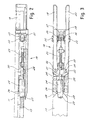
- Fig.2 shows a longitudinal cross section side view of Fig. 1,
- Fig. 3 shows a plan view of the device of Fig. 1 with parts removed, and
- Fig. 4 shows a view similar to that of Fig. 3 but with the device in release position.
- With reference to the figures Fig. 1 shows diagrammatically a release device indicated as a whole by
reference number 10 comprising a supporting rod orplate 11 designed to be connected under the wing of a gate indicated partially in broken lines withreference number 12. Therod 11 is mounted in a freely turning manner on avertical axis 13. Theaxis 13 can for example coincide with the rotation axis of the gate. On theaxis 13 is mounted coaxially asleeve 14 which also turns freely. - From the
sleeve 14 projects radially alever 15 designed to be connected to anactuator 16 for powered gate movement. The actuator, as may readily be imagined by one skilled in the art, can naturally be of any known type suited to acting on thelever 15 to rotate the sleeve around theaxis 13. - From the
sleeve 14 projects radially also a second engagement lever orplate 17 whose end far from the sleeve is engaged in areleasable constraint mechanism 18 supported integrally beneath therod 11. As clarified below, the constraint mechanism is releasable through operation of either of the two levers 19, 20 after operation with asuitable wrench 21 of acorresponding lock - As may be seen in Figures 2 and 3 the
constraint mechanism 18 comprises aboxed shell 28 whose upper wall can advantageously consist of the plate orrod 11 screwed thereto. Theshell 28 contains abolt 24 which is thrust outward by elastic means such as ahelical spring 25 so as to engage oneend 26 of the bolt in acomplementary seat 27 on the end of thelever 17 when thelever 17 is parallel to therod 11. - The
seat 27 and theend 26 are slightly tapered to permit engagement with minimal play and avoid mutual restraint. The taper is however limited with respect to the angle of friction between theseat 27 and the bolt to avoid the bolt being thrust axially by a simple moment applied between thelever 17 and therod 11 and overcoming the action of thespring 25. - The
bolt 24 has at the rear atang 29 defining athrust surface 30 on which act independently cam ends orsurfaces operating levers axis 13. Thethrust spring 25 can act axially on thetang 29 advantageously. In rest position the twooperating levers plate 11 on the two sides of the gate. As may be seen in Fig. 3 the levers can even partially form a mechanism shell side wall leaving free one of their rear ends for gripping and operation. - By moving an
operating lever seat 27 and permit free rotation of theplate 11 and thus the gate fastened thereto with respect to thelever 15. To prevent inappropriate operation of thelevers key lock plug shell 28. - When necessary to disengage the actuator from the gate it is sufficient thus to disengage one of the two locks and pull the corresponding operating lever. Disengagement of the bolt is ensured by the fact that the operating levers act directly on the bolt to cause it to retract from the engagement seat. Even if foreign matter were to enter the mechanism the ample arm of the operating levers would permit unlocking the bolt.
- The structure is simple and reliable and emergency disengagement is always ensured. In addition, the locks act only to hold the levers in the rest position. They therefore must not resist the gate movement force. In case of breakage of the lock under conditions of free movement of the operating levers the disengagement mechanism remains fully operational for both engagement and disengagement of the device. The existence of two independent operating levers on opposite sides of the gate permits convenient manual operation from either side of the gate and makes the mechanism more reliable.
- For automatic resetting after operation of the disengagement device the
bolt reception seat 27 may haveinclined side surfaces 39 to facilitate retraction of the bolt during realignment movement of thelever 17 and theplate 11. Thus it is sufficient to bring the operating levers back to the rest position to cause the actuator to again engage automatically with the gate upon the first operation of the powered actuator to bring thelever 17 to meet the bolt. - Is now clear that the preset purposes have been achieved. Naturally the above description of an embodiment applying the innovative principles of the present invention is given by way of non-limiting example of said principles within the scope of the exclusive right claimed here. For example, the sizing of the various parts can vary depending on specific exigencies. The rotation axes of the
parts axis 13 can also not coincide with the gate axis. In the latter case there can be provided known kinematic mechanisms, for example shoes and cranks, for connection between the gate and thearm 11.
Claims (8)
- Device designed to be placed between a gate and a powered actuator to permit release on command and free movement of the gate with respect to the actuator and comprising a first plate (11) designed to be fastened to the gate and a second plate (17) designed to be connected kinetically to the actuator with the first and second plate being supported to rotate around their own rotation axis (13) and means (18) of engagement of a bolt (24) being arranged to engage between the first and second plate to make them integral characterized in that said device comprises two operating levers (19,20) arranged on each side of the said means of engagement (18) and having cam surfaces (31,32) to cause independent backing of the bolt (24) of the engagement means (18) against the thrust of elastic means (25) to move it to a disengagement position upon movement of one of the two operating levers from a rest position to an operating position.
- Device in accordance with claim 1 characterized in that it comprises locks (22,23) for locking the operating levers (19,20) in their rest position.
- Device in accordance with claim 2 characterized in that the locks (22,23) are both arranged each facing a respective operating lever (19,20).
- Device in accordance with claim 2 characterized in that the operating levers (19,20) are pivoted on axes parallel to said rotation axis (13) and are arranged in rest position mutually parallel on each side of said means of engagement (18).
- Device in accordance with claim 1 characterized in that for retraction of the bolt (24) the cam surfaces (31,32) of the operating levers act on a thrust surface (30) which is integral with a tang (29) projecting from the rear of the bolt.
- Device in accordance with claim 5 characterized in that the elastic means are a helical spring (25) acting on said tang (29).
- Device in accordance with claim 5 characterized in that the bolt (24) and the operating levers (19,20) are supported on the first plate (11) and the second plate (17) has in its head a seat (27) for bolt engagement and having laterally inclined surfaces (39) to facilitate snap engagement of said bolt in said seat.
- Device in accordance with claim 1 characterized in that the second plate (17) is rotatable around said rotation axis (13) for interposition of a sleeve (14) from which projects radially a lever (15) for connection to the actuator.
Applications Claiming Priority (2)
| Application Number | Priority Date | Filing Date | Title |
|---|---|---|---|
| IT1997MI000075U IT236446Y1 (en) | 1997-02-05 | 1997-02-05 | MANUAL RELEASE DEVICE OF A GATE FROM A RESPECTIVE MOTORIZED ACTUATOR |
| ITMI970075U | 1997-02-05 |
Publications (2)
| Publication Number | Publication Date |
|---|---|
| EP0857845A1 EP0857845A1 (en) | 1998-08-12 |
| EP0857845B1 true EP0857845B1 (en) | 2001-08-16 |
Family
ID=11375637
Family Applications (1)
| Application Number | Title | Priority Date | Filing Date |
|---|---|---|---|
| EP98200285A Expired - Lifetime EP0857845B1 (en) | 1997-02-05 | 1998-02-02 | Device for manual release of a gate from a respective powered actuator |
Country Status (6)
| Country | Link |
|---|---|
| US (1) | US6032329A (en) |
| EP (1) | EP0857845B1 (en) |
| AT (1) | ATE204359T1 (en) |
| DE (1) | DE69801343T2 (en) |
| ES (1) | ES2162387T3 (en) |
| IT (1) | IT236446Y1 (en) |
Families Citing this family (12)
| Publication number | Priority date | Publication date | Assignee | Title |
|---|---|---|---|---|
| DE10004257C2 (en) * | 2000-02-01 | 2003-11-06 | Sommer Antriebs & Funktechnik | actuator |
| US6651386B2 (en) * | 2001-07-13 | 2003-11-25 | Homer C. Long | Emergency gate opening apparatus |
| CA2456916C (en) * | 2002-03-01 | 2011-02-22 | The Chamberlain Group, Inc. | Universal power operator |
| US7004670B2 (en) * | 2002-05-23 | 2006-02-28 | The Chamberlain Group, Inc. | Manual disconnect apparatus and method |
| ITRM20060042A1 (en) * | 2006-01-27 | 2007-07-28 | Findisa S R L | UNLOCK RELEASE SYSTEM FOR THE RELEASE OF HYDRAULIC ACTUATORS FOR AUTOMATIC OPENINGS |
| US20120117885A1 (en) * | 2010-11-15 | 2012-05-17 | Degott Danny | Pedestrian Gate Closer |
| IT1403000B1 (en) * | 2010-11-18 | 2013-09-27 | Came Group S P A | LOCK FOR GATE. |
| US10125525B2 (en) | 2013-02-01 | 2018-11-13 | Michael Presutti | Door barricade |
| US9644408B2 (en) | 2013-02-01 | 2017-05-09 | Michael Presutti | Method and device for barricading a door |
| FR3002268B1 (en) * | 2013-02-21 | 2018-01-05 | Semco Sarl | EQUIPMENT ACCESSING A PLACE, INCLUDING AN OPENING AND A SYSTEM FOR MAINTAINING THE OPENING IN CLOSURE POSITION |
| US10316556B2 (en) | 2016-01-25 | 2019-06-11 | Campus Safety Products, LLC | Door barricade |
| US10214948B2 (en) | 2016-01-25 | 2019-02-26 | Campus Safety Products, LLC | Door barricade |
Family Cites Families (8)
| Publication number | Priority date | Publication date | Assignee | Title |
|---|---|---|---|---|
| US4007557A (en) * | 1975-03-03 | 1977-02-15 | The Stanley Works | Pivot hung power operated door and inertia insensitive disconnectable drive linkage therefor |
| US4190926A (en) * | 1979-02-27 | 1980-03-04 | John Cronin | Door guard |
| US4403449A (en) * | 1980-03-03 | 1983-09-13 | Richmond Moscow K | Gate-opening and closing apparatus and method |
| US4375140A (en) * | 1981-04-23 | 1983-03-01 | Excell Machine Company, Inc. | Door opener for bus and the like |
| FR2569222B1 (en) * | 1984-08-17 | 1989-06-16 | Sapa Sarl | DEVICE FOR AUTOMATICALLY OPENING AND CLOSING GATES |
| FR2720435B3 (en) * | 1994-05-27 | 1996-08-23 | Jean Jacques Vial | Device for fixing the end of a control member to a leaf of doors or gates. |
| FR2735516B1 (en) * | 1995-06-16 | 1997-08-14 | Simu | OPERATING DEVICE FOR GATE OR OTHER CLOSING PANEL |
| US5862569A (en) * | 1996-10-09 | 1999-01-26 | Wood; Don | Door closer holding plate |
-
1997
- 1997-02-05 IT IT1997MI000075U patent/IT236446Y1/en active IP Right Grant
-
1998
- 1998-01-29 US US09/015,195 patent/US6032329A/en not_active Expired - Lifetime
- 1998-02-02 EP EP98200285A patent/EP0857845B1/en not_active Expired - Lifetime
- 1998-02-02 AT AT98200285T patent/ATE204359T1/en not_active IP Right Cessation
- 1998-02-02 ES ES98200285T patent/ES2162387T3/en not_active Expired - Lifetime
- 1998-02-02 DE DE69801343T patent/DE69801343T2/en not_active Expired - Lifetime
Also Published As
| Publication number | Publication date |
|---|---|
| DE69801343T2 (en) | 2002-06-13 |
| ITMI970075U1 (en) | 1998-08-05 |
| EP0857845A1 (en) | 1998-08-12 |
| ES2162387T3 (en) | 2001-12-16 |
| DE69801343D1 (en) | 2001-09-20 |
| ATE204359T1 (en) | 2001-09-15 |
| IT236446Y1 (en) | 2000-08-17 |
| US6032329A (en) | 2000-03-07 |
Similar Documents
| Publication | Publication Date | Title |
|---|---|---|
| US6032329A (en) | Device for manual release of a gate from a respective powered actuator | |
| KR101637820B1 (en) | Retractable handle system for vehicle | |
| RU2764429C2 (en) | Device of door lock unlocking | |
| KR100186498B1 (en) | Multi-point locking device | |
| JP5541630B2 (en) | Electric swing plug door operator with auxiliary door lock mechanism | |
| US4668134A (en) | Apparatus for orientation of tool on workpiece | |
| JP2008514882A (en) | Object fixing device to rail | |
| NZ527010A (en) | High strength lever handle lock mechanism | |
| WO1998002630A1 (en) | Lockset with motorized system for locking and unlocking | |
| US6860503B2 (en) | Retractile motor-vehicle trailer hitch | |
| GB2344781A (en) | Tube gripping apparatus | |
| GB9000074D0 (en) | Gear mechanisms for side/bottom-hung doors | |
| EP2326783B1 (en) | Drive device for entrance/exit devices with coupling | |
| US5660373A (en) | Extendable and retractable lifting apparatus | |
| US7021683B2 (en) | Slidable door lock brace | |
| EP0380869B1 (en) | Door Locking Arrangement | |
| WO2005111347A1 (en) | Divided spindle | |
| JPS6150807A (en) | Separable trailer joint for automobile | |
| EP0018252A1 (en) | Suspension device for a propulsive unit attached to the fuselage of an aircraft, equipment and method of putting it into use | |
| GB2120637A (en) | Telescopic screw jacks for e.g.vehicle roof panels | |
| CA3053062C (en) | Low profile gap mitigation device | |
| EP0789126B1 (en) | A window comprising a pasquil locking mechanism and a window operator with an operating member | |
| US5941580A (en) | Clamping type lock assembly | |
| PL177584B1 (en) | Lock mechanism | |
| GB2150630A (en) | Locking system |
Legal Events
| Date | Code | Title | Description |
|---|---|---|---|
| PUAI | Public reference made under article 153(3) epc to a published international application that has entered the european phase |
Free format text: ORIGINAL CODE: 0009012 |
|
| AX | Request for extension of the european patent |
Free format text: AL;LT;LV;MK;RO;SI |
|
| 17P | Request for examination filed |
Effective date: 19981204 |
|
| AKX | Designation fees paid |
Free format text: AT CH DE ES FR GB IT LI |
|
| RBV | Designated contracting states (corrected) |
Designated state(s): AT CH DE ES FR GB IT LI |
|
| GRAG | Despatch of communication of intention to grant |
Free format text: ORIGINAL CODE: EPIDOS AGRA |
|
| 17Q | First examination report despatched |
Effective date: 20001010 |
|
| GRAG | Despatch of communication of intention to grant |
Free format text: ORIGINAL CODE: EPIDOS AGRA |
|
| GRAH | Despatch of communication of intention to grant a patent |
Free format text: ORIGINAL CODE: EPIDOS IGRA |
|
| GRAH | Despatch of communication of intention to grant a patent |
Free format text: ORIGINAL CODE: EPIDOS IGRA |
|
| GRAA | (expected) grant |
Free format text: ORIGINAL CODE: 0009210 |
|
| AK | Designated contracting states |
Kind code of ref document: B1 Designated state(s): AT CH DE ES FR GB IT LI |
|
| PG25 | Lapsed in a contracting state [announced via postgrant information from national office to epo] |
Ref country code: AT Free format text: LAPSE BECAUSE OF FAILURE TO SUBMIT A TRANSLATION OF THE DESCRIPTION OR TO PAY THE FEE WITHIN THE PRESCRIBED TIME-LIMIT Effective date: 20010816 |
|
| REF | Corresponds to: |
Ref document number: 204359 Country of ref document: AT Date of ref document: 20010915 Kind code of ref document: T |
|
| REG | Reference to a national code |
Ref country code: CH Ref legal event code: EP |
|
| REF | Corresponds to: |
Ref document number: 69801343 Country of ref document: DE Date of ref document: 20010920 |
|
| REG | Reference to a national code |
Ref country code: CH Ref legal event code: NV Representative=s name: PATENTANWAELTE SCHAAD, BALASS, MENZL & PARTNER AG |
|
| ET | Fr: translation filed | ||
| REG | Reference to a national code |
Ref country code: ES Ref legal event code: FG2A Ref document number: 2162387 Country of ref document: ES Kind code of ref document: T3 |
|
| REG | Reference to a national code |
Ref country code: GB Ref legal event code: IF02 |
|
| PLBE | No opposition filed within time limit |
Free format text: ORIGINAL CODE: 0009261 |
|
| STAA | Information on the status of an ep patent application or granted ep patent |
Free format text: STATUS: NO OPPOSITION FILED WITHIN TIME LIMIT |
|
| 26N | No opposition filed | ||
| REG | Reference to a national code |
Ref country code: FR Ref legal event code: PLFP Year of fee payment: 19 |
|
| PGFP | Annual fee paid to national office [announced via postgrant information from national office to epo] |
Ref country code: IT Payment date: 20160209 Year of fee payment: 19 |
|
| REG | Reference to a national code |
Ref country code: FR Ref legal event code: PLFP Year of fee payment: 20 |
|
| PGFP | Annual fee paid to national office [announced via postgrant information from national office to epo] |
Ref country code: DE Payment date: 20170125 Year of fee payment: 20 Ref country code: FR Payment date: 20170126 Year of fee payment: 20 Ref country code: CH Payment date: 20170214 Year of fee payment: 20 |
|
| PGFP | Annual fee paid to national office [announced via postgrant information from national office to epo] |
Ref country code: GB Payment date: 20170201 Year of fee payment: 20 |
|
| PGFP | Annual fee paid to national office [announced via postgrant information from national office to epo] |
Ref country code: ES Payment date: 20170127 Year of fee payment: 20 |
|
| REG | Reference to a national code |
Ref country code: DE Ref legal event code: R071 Ref document number: 69801343 Country of ref document: DE |
|
| REG | Reference to a national code |
Ref country code: CH Ref legal event code: PL |
|
| REG | Reference to a national code |
Ref country code: GB Ref legal event code: PE20 Expiry date: 20180201 |
|
| PG25 | Lapsed in a contracting state [announced via postgrant information from national office to epo] |
Ref country code: IT Free format text: LAPSE BECAUSE OF NON-PAYMENT OF DUE FEES Effective date: 20170202 |
|
| PG25 | Lapsed in a contracting state [announced via postgrant information from national office to epo] |
Ref country code: GB Free format text: LAPSE BECAUSE OF EXPIRATION OF PROTECTION Effective date: 20180201 |
|
| REG | Reference to a national code |
Ref country code: ES Ref legal event code: FD2A Effective date: 20180525 |
|
| PG25 | Lapsed in a contracting state [announced via postgrant information from national office to epo] |
Ref country code: ES Free format text: LAPSE BECAUSE OF EXPIRATION OF PROTECTION Effective date: 20180203 |