EP0857504A1 - Panel for toy construction system - Google Patents
Panel for toy construction system Download PDFInfo
- Publication number
- EP0857504A1 EP0857504A1 EP98300819A EP98300819A EP0857504A1 EP 0857504 A1 EP0857504 A1 EP 0857504A1 EP 98300819 A EP98300819 A EP 98300819A EP 98300819 A EP98300819 A EP 98300819A EP 0857504 A1 EP0857504 A1 EP 0857504A1
- Authority
- EP
- European Patent Office
- Prior art keywords
- panel
- legs
- connectors
- connector
- center
- Prior art date
- Legal status (The legal status is an assumption and is not a legal conclusion. Google has not performed a legal analysis and makes no representation as to the accuracy of the status listed.)
- Granted
Links
Images


Classifications
-
- A—HUMAN NECESSITIES
- A63—SPORTS; GAMES; AMUSEMENTS
- A63H—TOYS, e.g. TOPS, DOLLS, HOOPS OR BUILDING BLOCKS
- A63H33/00—Other toys
- A63H33/04—Building blocks, strips, or similar building parts
- A63H33/042—Mechanical, electrical, optical, pneumatic or hydraulic arrangements; Motors
-
- A—HUMAN NECESSITIES
- A63—SPORTS; GAMES; AMUSEMENTS
- A63H—TOYS, e.g. TOPS, DOLLS, HOOPS OR BUILDING BLOCKS
- A63H29/00—Drive mechanisms for toys in general
- A63H29/22—Electric drives
Definitions
- the present invention is directed to a toy construction system, and in particular a panel which may be incorporated in such a toy construction system.
- the panel of the present invention is designed to be used with a toy construction system comprised of a combination of connector elements and structural elements which can be combined in various forms to form composite structures.
- the toy construction system includes a plurality of hub-like connector elements and rod-like strut elements which can be combined in various forms to create rigid skeletal structures.
- the connectors of this system include gripping arms adapted for lateral, snap-in engagement of the struts and include cavities disposed radially around a center hub portion between the hub portion and the gripping arms.
- the panel of the present invention is suitable to house a photovoltaic cell or solar panel, or the like, and includes legs which are sized and shaped for a tight frictional engagement with the cavities of the connectors such that the panel can be incorporated in an assembly comprised of the connectors and struts.
- the legs are located on the bottom of the panel, one at each corner and two near the center.
- connector elements can be mounted on the legs in various combinations to allow the panel to be incorporated in a larger assembly composed of the connectors and struts.
- the legs located at the four corners of the panel are spaced from the sides thereof a distance such that one connector can be used to engage the legs of two adjacent panels thereby allowing the two panels to be joined together.
- the center legs and the corner legs are located such that connectors mounted thereon can be interconnected by a combination of connector elements and strut elements thereby providing a rigid support for the panel.
- the known hub-like connector elements have a plurality of generally radially oriented sockets for receiving and lockingly engaging end portions of the struts.
- the connectors include a plurality of spaced-apart gripping arms disposed radially around a center hub portion.
- the gripping arms define socket-forming recessed adapted for lateral snap-in insertion of the struts.
- the end extremities of the struts are formed with an annular groove, defining a flanged end such that the strut is locked against axial and lateral withdrawal from the connector once installed.
- the connectors are provided in various configurations including a planar "snowflake" configuration having eight sockets disposed radially 360 degrees around, and equidistant from, a center hub portion. Also disclosed is a multiplanar, composite connector formed of two connectors, each including a special recess adapted such that the two connectors can be assembled in a 90 degree relationship to one another.
- the panel of the present invention is particularly suitable for motorized structures composed of assemblies of the connectors and strut elements of the toy construction system.
- the panel can be placed adjacent or mounted on such structures and can provide power to the motorized structure with an enclosed solar cell, or other power source.
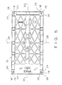
- the panel 10 of the present invention can house a power source such as a solar cell 12, which can power a motor 14 for use in operating a structure comprised of the connectors and struts of the toy construction set described above.
- the panel 10 includes a panel body 16 and a plurality of outside legs 18 projecting therefrom.
- the outside legs 18 are located adjacent the corners 26 of the panel body 16 and a pair of inside legs 20 are located adjacent the center 22 of the panel body 16.
- the inside and outside legs 18, 20 are all of the same length such that the panel 10 can be placed on a supporting surface such as a table or the like.
- the outside legs 18 are preferably arranged symmetrically about the center 22 of the panel body 16 and are located substantially equidistant from the sides 24 of the corners 26 of the panel body 16.
- the inside legs 20 are disposed along the lateral center axis 28 of the panel body 16 on opposite sides of the longitudinal center axis 30 and are spaced substantially equidistant from the longitudinal center axis 30.
- the panel also preferably includes a pair of tubular recesses 31 located on the top surface 33 of the panel 10.
- the tubular recesses 31 are preferably sized to frictionally engage a strut element inserted therein such that the strut, once inserted, will remain perpendicular to the top surface 33 of the panel 10. With the insertion of a strut element having a certain length, the proper distance between the solar cell 12 and a light source such as a light bulb can be easily maintained.
- the inside and outside legs 18, 20 are sized and shaped for tight frictional engagement with cavities 32 of the connectors 34 of the toy construction set described above such that the connectors 34 can be securely mounted on the panel 10 for incorporating the panel in a structure formed of an assembly of the connectors 34 and struts 36.
- the outside legs 18 are preferably located such that when a connector 34 is mounted thereon, the center of a hub portion 38 thereof is aligned adjacent, and preferably directly over, the corner 26 of the panel body 16. As will be described in detail below, this allows multiple panels lo to be joined together by individual connectors 34.
- the inside legs 20 are preferably aligned to engage separate cavities 40, 42 of the center connector 44 such that the orientation of the center connector 44 is fixed relative to the panel body 16. Also, the location of the inside legs 20 with respect to the longitudinal and lateral center axes 28, 30, described above, provide that the center connector 44 will be aligned with the lateral and longitudinal center axes 28, 30 and with the center 22 of the panel body 16.
- inside and outside legs 18, 20 are oriented such that connectors mounted thereon can be interconnected by a combination of connectors 34 and struts 36, 37 as shown, and such that the connectors 34 can be interconnected with the center connector 44 by a combination of struts 48, 49 and connectors 50 thereby providing a stable base or support for the panel 10.
- the panel body 16 has a width and a length which are substantially equal to integer multiples of a diameter of the connectors 34.
- the panel body 16 has a width equal to approximately twice the diameter of a connector 34 and a length equal to approximately four times the diameter of a connector 34.
- the connector elements have spoke-like radial walls 58 extending outward from the hub portion 38 to the gripping arms.
- the outward ends of adjacent radial walls 58 are connected by web sections 60, each of which forms an inner wall of one of the socket-forming recesses and forms an outer wall of one of the cavities 32.
- the cavities 32 are each bounded by the hub portion 38, a pair of adjacent radial walls 58 and a web section 60.
- the strut elements are provided in several, predetermined lengths such that in a system of "n" different lengths, the length of each strut is determined according to the formula:
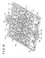
- two panels 10, 110 can be joined together using connectors 34, 44, 144 and a strut 58.
- the outside legs 18 are located such that the hub portion 38 of a connector 34 mounted thereon is aligned with the corner 26 (hidden) of the panel body 16.
- the connector 34 is also aligned to accept an outside leg 118 of the second panel 110 thereby joining the two panels 10, 110 together in a close abutting relationship.
- the width dimension of the panel body 16 provides that the center connectors 44, 144 can be interconnected with a single strut 58 of the toy construction system.
- the panels 10, 110 are shown joined in a side-to-side relationship, however it should be appreciated that the configuration and dimensions discussed above also provide that the two panels can be similarly joined in an end-to-end relationship.
- the panel body 16 includes a recess 52 intermediate the two inside legs 20 which allows a multiplanar, composite connector, such as the center connector 44 depicted, to mount on the panel body 16 in such a manner that it is substantially planar with the connectors 34 mounted on the outside legs 18.
- a recess 52 is beneficial because the multiplanar connector 44 is comprised of two portions, one of which extends a short distance below the other.
- a first part 54 extends outwardly, perpendicular to the panel body 16 and includes a portion which extends below a second part 56.
- the bottom of the recess 52 should be below the respective bases of the outside legs 18, i.e. below where the outside legs 18 meet the panel body 16.
- the dimensions of the recess can vary, however the inside legs 20 are preferably spaced from the recess 52 such that the bases thereof lie in substantially the same plane as the bases of the outside legs thereby providing a stable, aligned abutting surface for the connector 44.
Landscapes
- Toys (AREA)
Abstract
Description
- Lx =
- (1.414)(x-1) * Dmin-(2*d), where
- Lx =
- the length of the xth strut of a series of 1 to "n",
- Dmin =
- the spacing between hub axis of two connector elements joined by the shortest strut element of the series, and
- d =
- the distance from the hub axis to the end wall of the socket-forming section.
Claims (14)
- A panel for use in combination with a toy construction set of the type having a plurality of connector elements and rod-like struts engageable with said connector elements to form a coherent structure wherein said connector elements have a center hub portion with a plurality of pairs of spaced-apart gripping arms disposed radially therearound defining socket-forming recesses adapted for lateral snap-in engagement of said struts, and wherein said connectors have cavities disposed radially around said hub portion between said hub portion and said socket-forming recesses, said panel comprising:(a) a panel body;(b) a plurality of legs extending from said panel body;(c) said legs being adapted for tight frictional engagement with said cavities of said connectors; and(d) said legs being located such that connectors mounted thereon can be interconnected to each other using said connectors and struts;(e) whereby said panel structure can be incorporated in combination with a structure formed of an assembly of said connectors and struts.
- A panel structure as in claim 1, wherein said panel comprises an outside leg disposed adjacent a periphery of said panel and spaced from said periphery a distance such that, when a connector is mounted on said outside leg, a center of a hub portion thereof lies adjacent said periphery.
- A panel structure as in claim 2, wherein said panel comprises four outside legs, each outside leg being disposed adjacent a corner of said panel substantially equidistant from two sides of said corner such that, when a connector is mounted on said outside leg, a center of a hub portion of said connector lies adjacent said corner.
- A panel structure as in claim 3, wherein said four outside legs are arranged substantially symmetrically about a center axis of said panel.
- A panel structure as in claim 2, wherein:(a) said panel comprises two inside legs adapted to engage separate cavities of a connector; and(b) said inside and outside legs being located such that a connector mounted on said outside leg is connectable to a connector mounted on said two inside legs by a combination of connectors and struts to fix the positions thereof relative to said panel.
- A panel structure as in claim 5, wherein said two inside legs are disposed adjacent a center of said panel such that, when a connector is mounted on said inside legs, a center of a hub portion thereof lies on said center of said panel.
- A panel structure as in claim 6, wherein:(a) said connectors have two cavities spaced substantially equidistant from opposed sides of said hub portion thereof and aligned with an axis of an opposed pair of socket-forming recesses;(b) said two inside legs are disposed along a first center axis of said panel on opposed sides of a second center axis thereof; and(d) said inside legs being substantially equidistant from said second center axis such that, when mounted on said two inside legs, said connector is aligned with said center of said panel and with said first and second center axes thereof.
- A panel structure as in claim 7, wherein said panel comprises four outside legs, each outside leg being disposed adjacent a corner of said panel substantially equidistant from two sides of said corner such that, when a connector is mounted on said outside leg, a center of a hub portion of said connector lies adjacent said corner.
- A panel structure as in claim 8, wherein said inside and outside legs are located such that, a plurality of connectors can be mounted on said panel, said connectors being connectable to others by a combination of said connectors and said struts.
- A panel structure as in claim 9 wherein said two inside legs are disposed along a lateral center axis of said panel.
- A panel structure as in claim 9, wherein said panel is substantially rectangular and has a length and a width each substantially equal to integer multiples of a diameter of one of said connectors.
- A panel structure as in claim 11, wherein said panel has a width substantially equal to twice said diameter and a length substantially equal to four times said diameter.
- A panel structure as in claim 2, wherein said panel is substantially rectangular and has a length and a width each substantially equal to integer multiples of a diameter of one of said connectors.
- A panel structure as in claim 13, wherein said panel has a width substantially equal to twice said diameter and a length substantially equal to four times said diameter.
Applications Claiming Priority (2)
| Application Number | Priority Date | Filing Date | Title |
|---|---|---|---|
| US08/795,012 US5904606A (en) | 1997-02-05 | 1997-02-05 | Panel for toy construction system |
| US795012 | 1997-02-05 |
Publications (2)
| Publication Number | Publication Date |
|---|---|
| EP0857504A1 true EP0857504A1 (en) | 1998-08-12 |
| EP0857504B1 EP0857504B1 (en) | 2003-09-10 |
Family
ID=25164383
Family Applications (1)
| Application Number | Title | Priority Date | Filing Date |
|---|---|---|---|
| EP98300819A Expired - Lifetime EP0857504B1 (en) | 1997-02-05 | 1998-02-04 | A toy construction system, in particular with a panel |
Country Status (3)
| Country | Link |
|---|---|
| US (1) | US5904606A (en) |
| EP (1) | EP0857504B1 (en) |
| DE (1) | DE69817890D1 (en) |
Families Citing this family (18)
| Publication number | Priority date | Publication date | Assignee | Title |
|---|---|---|---|---|
| US6592421B1 (en) * | 1996-05-31 | 2003-07-15 | Eric Clever | Totipotent hub for construction toy system |
| AT4237U1 (en) | 2000-01-26 | 2001-04-25 | Tesma Motoren Getriebetechnik | DAMPING ELEMENT AND FUEL TANK WITH AT LEAST ONE DAMPING ELEMENT |
| US6672931B1 (en) | 2000-11-14 | 2004-01-06 | Jim Bagley | Interconnectable model construction elements |
| USD478361S1 (en) | 2002-09-16 | 2003-08-12 | Lee Valley Tools, Ltd. | Construction toy piece |
| USD474512S1 (en) | 2002-09-16 | 2003-05-13 | Lee Valley Tools, Ltd. | Construction toy piece |
| WO2004071607A2 (en) * | 2003-02-07 | 2004-08-26 | Gracewood, Inc. | Improved interconnectable model construction elements |
| US20050186021A1 (en) * | 2004-02-12 | 2005-08-25 | Keith Savas Product Development, Llc | Hub and spoke panel connector |
| EP1796804A4 (en) * | 2004-09-02 | 2009-11-11 | Dane Scarborough | Toy construction set method and apparatus |
| US20090149110A1 (en) * | 2004-09-02 | 2009-06-11 | Dane Scarborough | Toy construction set |
| US20060084357A1 (en) * | 2004-10-15 | 2006-04-20 | Rosen Lawrence I | Illuminated toy construction kit |
| US7506477B2 (en) * | 2006-06-30 | 2009-03-24 | Lumeta, Inc. | Profile roof tile with integrated photovoltaic module |
| TWD121562S1 (en) * | 2007-03-16 | 2008-03-01 | 輝庭企業股份有限公司 | Connectors |
| WO2008154034A2 (en) * | 2007-06-11 | 2008-12-18 | Zinkotek | Interlocking toy |
| USD588651S1 (en) | 2008-06-11 | 2009-03-17 | Zinkotek | Interlocking toy |
| USD597149S1 (en) | 2008-06-11 | 2009-07-28 | Zinkotek | Interlocking toy |
| USD588208S1 (en) * | 2008-06-11 | 2009-03-10 | Zinkotek | Interlocking toy |
| US9199182B2 (en) * | 2011-03-11 | 2015-12-01 | Larry David Hunts | Connection system for mechanical components |
| US9498703B2 (en) * | 2013-03-13 | 2016-11-22 | Stat Ventures, Inc. | Assembly kit for three dimensional works |
Citations (7)
| Publication number | Priority date | Publication date | Assignee | Title |
|---|---|---|---|---|
| US4129975A (en) * | 1977-03-09 | 1978-12-19 | Matrix Toys, Inc. | Construction set having clip fasteners |
| GB2002643A (en) * | 1977-08-19 | 1979-02-28 | Fischer Artur | Toy construction kit |
| US5061219A (en) | 1990-12-11 | 1991-10-29 | Magic Mold Corporation | Construction toy |
| EP0490033A1 (en) * | 1990-12-11 | 1992-06-17 | Connector Set Limited Partnership | Construction toy |
| US5137486A (en) | 1990-12-11 | 1992-08-11 | Connector Set Toy Company | Multi-planar connector element for construction toy |
| US5199919A (en) | 1990-12-11 | 1993-04-06 | Connector Set Limited Partnership | Construction toy system |
| DE29602205U1 (en) * | 1996-03-07 | 1996-06-13 | LEMO - SOLAR Lehnert Modellbau und Solartechnik GmbH, 74906 Bad Rappenau | Building block for building blocks |
Family Cites Families (3)
| Publication number | Priority date | Publication date | Assignee | Title |
|---|---|---|---|---|
| US3594940A (en) * | 1968-08-19 | 1971-07-27 | Yonezawa Toys Co | Assembly toy set |
| US4164091A (en) * | 1978-03-30 | 1979-08-14 | Lin Wen Ping | Building blocks set |
| US4571200A (en) * | 1984-11-15 | 1986-02-18 | Mattel, Inc. | Modular toy building set |
-
1997
- 1997-02-05 US US08/795,012 patent/US5904606A/en not_active Expired - Lifetime
-
1998
- 1998-02-04 EP EP98300819A patent/EP0857504B1/en not_active Expired - Lifetime
- 1998-02-04 DE DE69817890T patent/DE69817890D1/en not_active Expired - Lifetime
Patent Citations (7)
| Publication number | Priority date | Publication date | Assignee | Title |
|---|---|---|---|---|
| US4129975A (en) * | 1977-03-09 | 1978-12-19 | Matrix Toys, Inc. | Construction set having clip fasteners |
| GB2002643A (en) * | 1977-08-19 | 1979-02-28 | Fischer Artur | Toy construction kit |
| US5061219A (en) | 1990-12-11 | 1991-10-29 | Magic Mold Corporation | Construction toy |
| EP0490033A1 (en) * | 1990-12-11 | 1992-06-17 | Connector Set Limited Partnership | Construction toy |
| US5137486A (en) | 1990-12-11 | 1992-08-11 | Connector Set Toy Company | Multi-planar connector element for construction toy |
| US5199919A (en) | 1990-12-11 | 1993-04-06 | Connector Set Limited Partnership | Construction toy system |
| DE29602205U1 (en) * | 1996-03-07 | 1996-06-13 | LEMO - SOLAR Lehnert Modellbau und Solartechnik GmbH, 74906 Bad Rappenau | Building block for building blocks |
Also Published As
| Publication number | Publication date |
|---|---|
| US5904606A (en) | 1999-05-18 |
| DE69817890D1 (en) | 2003-10-16 |
| EP0857504B1 (en) | 2003-09-10 |
Similar Documents
| Publication | Publication Date | Title |
|---|---|---|
| US5904606A (en) | Panel for toy construction system | |
| US4209934A (en) | Modular toy building units | |
| RU2286193C2 (en) | System for connecting of modules by magnetic attachment for constructing stable lattice structures | |
| EP0490033B2 (en) | Construction toy | |
| US4585422A (en) | Toy construction kit | |
| US3648404A (en) | Connector unit having radial arms for straight or angular connections | |
| US5452681A (en) | Collapsible animal house assembly | |
| US4819402A (en) | Structural element for constructional systems | |
| US5527201A (en) | Toy construction kit with interconnecting building pieces | |
| US6189271B1 (en) | Building systems | |
| US4164091A (en) | Building blocks set | |
| US5137485A (en) | Toy construction set with improved radial and axial connectability and expandability | |
| US20040134869A1 (en) | Modular storage assembly | |
| US5073138A (en) | Modular gear and frame toy | |
| US5954562A (en) | Building block assembly | |
| CA2098275A1 (en) | Interlocking structural members with edge connectors | |
| JPS58500840A (en) | Elements and accessories of construction or assembly sets | |
| US3405479A (en) | Toy building block | |
| EP0048560A1 (en) | Building block set | |
| US5346420A (en) | Gearing and drive mechanism for construction toy system | |
| WO2017094981A1 (en) | Lego - type triangular cat play structure | |
| US5738558A (en) | Motor for toy construction system | |
| US6622447B1 (en) | Modular hub and strut structural system | |
| US4603853A (en) | Modular frame structure and building system | |
| US4890952A (en) | Sawbuck construction and bracket |
Legal Events
| Date | Code | Title | Description |
|---|---|---|---|
| PUAI | Public reference made under article 153(3) epc to a published international application that has entered the european phase |
Free format text: ORIGINAL CODE: 0009012 |
|
| AK | Designated contracting states |
Kind code of ref document: A1 Designated state(s): DE FR GB |
|
| AX | Request for extension of the european patent |
Free format text: AL;LT;LV;MK;RO;SI |
|
| 17P | Request for examination filed |
Effective date: 19990204 |
|
| AKX | Designation fees paid |
Free format text: DE FR GB |
|
| RBV | Designated contracting states (corrected) |
Designated state(s): DE FR GB |
|
| 17Q | First examination report despatched |
Effective date: 20020531 |
|
| GRAH | Despatch of communication of intention to grant a patent |
Free format text: ORIGINAL CODE: EPIDOS IGRA |
|
| RTI1 | Title (correction) |
Free format text: A TOY CONSTRUCTION SYSTEM, IN PARTICULAR WITH A PANEL |
|
| RAP1 | Party data changed (applicant data changed or rights of an application transferred) |
Owner name: CONNECTOR SET LIMITED PARTNERSHIP |
|
| GRAH | Despatch of communication of intention to grant a patent |
Free format text: ORIGINAL CODE: EPIDOS IGRA |
|
| GRAA | (expected) grant |
Free format text: ORIGINAL CODE: 0009210 |
|
| AK | Designated contracting states |
Kind code of ref document: B1 Designated state(s): DE FR GB |
|
| PG25 | Lapsed in a contracting state [announced via postgrant information from national office to epo] |
Ref country code: FR Free format text: LAPSE BECAUSE OF FAILURE TO SUBMIT A TRANSLATION OF THE DESCRIPTION OR TO PAY THE FEE WITHIN THE PRESCRIBED TIME-LIMIT Effective date: 20030910 |
|
| REG | Reference to a national code |
Ref country code: GB Ref legal event code: FG4D |
|
| RAP2 | Party data changed (patent owner data changed or rights of a patent transferred) |
Owner name: CONNECTOR SET LIMITED PARTNERSHIP |
|
| REF | Corresponds to: |
Ref document number: 69817890 Country of ref document: DE Date of ref document: 20031016 Kind code of ref document: P |
|
| PG25 | Lapsed in a contracting state [announced via postgrant information from national office to epo] |
Ref country code: DE Free format text: LAPSE BECAUSE OF FAILURE TO SUBMIT A TRANSLATION OF THE DESCRIPTION OR TO PAY THE FEE WITHIN THE PRESCRIBED TIME-LIMIT Effective date: 20031211 |
|
| PLBE | No opposition filed within time limit |
Free format text: ORIGINAL CODE: 0009261 |
|
| STAA | Information on the status of an ep patent application or granted ep patent |
Free format text: STATUS: NO OPPOSITION FILED WITHIN TIME LIMIT |
|
| 26N | No opposition filed |
Effective date: 20040614 |
|
| EN | Fr: translation not filed | ||
| PGFP | Annual fee paid to national office [announced via postgrant information from national office to epo] |
Ref country code: GB Payment date: 20090219 Year of fee payment: 12 |
|
| GBPC | Gb: european patent ceased through non-payment of renewal fee |
Effective date: 20100204 |
|
| PG25 | Lapsed in a contracting state [announced via postgrant information from national office to epo] |
Ref country code: GB Free format text: LAPSE BECAUSE OF NON-PAYMENT OF DUE FEES Effective date: 20100204 |