EP0857325B1 - An unmanned vehicle - Google Patents
An unmanned vehicle Download PDFInfo
- Publication number
- EP0857325B1 EP0857325B1 EP97936882A EP97936882A EP0857325B1 EP 0857325 B1 EP0857325 B1 EP 0857325B1 EP 97936882 A EP97936882 A EP 97936882A EP 97936882 A EP97936882 A EP 97936882A EP 0857325 B1 EP0857325 B1 EP 0857325B1
- Authority
- EP
- European Patent Office
- Prior art keywords
- vehicle
- installation
- supervisor
- transceiver
- unmanned
- Prior art date
- Legal status (The legal status is an assumption and is not a legal conclusion. Google has not performed a legal analysis and makes no representation as to the accuracy of the status listed.)
- Expired - Lifetime
Links
- 238000009434 installation Methods 0.000 claims abstract description 33
- 238000012544 monitoring process Methods 0.000 claims abstract description 13
- 230000003287 optical effect Effects 0.000 claims description 2
- 230000000903 blocking effect Effects 0.000 description 1
Images

Classifications
-
- G—PHYSICS
- G05—CONTROLLING; REGULATING
- G05D—SYSTEMS FOR CONTROLLING OR REGULATING NON-ELECTRIC VARIABLES
- G05D1/00—Control of position, course, altitude or attitude of land, water, air or space vehicles, e.g. using automatic pilots
- G05D1/02—Control of position or course in two dimensions
- G05D1/021—Control of position or course in two dimensions specially adapted to land vehicles
- G05D1/0231—Control of position or course in two dimensions specially adapted to land vehicles using optical position detecting means
-
- G—PHYSICS
- G05—CONTROLLING; REGULATING
- G05D—SYSTEMS FOR CONTROLLING OR REGULATING NON-ELECTRIC VARIABLES
- G05D1/00—Control of position, course, altitude or attitude of land, water, air or space vehicles, e.g. using automatic pilots
- G05D1/0011—Control of position, course, altitude or attitude of land, water, air or space vehicles, e.g. using automatic pilots associated with a remote control arrangement
-
- G—PHYSICS
- G05—CONTROLLING; REGULATING
- G05D—SYSTEMS FOR CONTROLLING OR REGULATING NON-ELECTRIC VARIABLES
- G05D1/00—Control of position, course, altitude or attitude of land, water, air or space vehicles, e.g. using automatic pilots
- G05D1/02—Control of position or course in two dimensions
- G05D1/021—Control of position or course in two dimensions specially adapted to land vehicles
- G05D1/0231—Control of position or course in two dimensions specially adapted to land vehicles using optical position detecting means
- G05D1/0234—Control of position or course in two dimensions specially adapted to land vehicles using optical position detecting means using optical markers or beacons
- G05D1/0236—Control of position or course in two dimensions specially adapted to land vehicles using optical position detecting means using optical markers or beacons in combination with a laser
-
- G—PHYSICS
- G05—CONTROLLING; REGULATING
- G05D—SYSTEMS FOR CONTROLLING OR REGULATING NON-ELECTRIC VARIABLES
- G05D1/00—Control of position, course, altitude or attitude of land, water, air or space vehicles, e.g. using automatic pilots
- G05D1/02—Control of position or course in two dimensions
- G05D1/021—Control of position or course in two dimensions specially adapted to land vehicles
- G05D1/0276—Control of position or course in two dimensions specially adapted to land vehicles using signals provided by a source external to the vehicle
- G05D1/0278—Control of position or course in two dimensions specially adapted to land vehicles using signals provided by a source external to the vehicle using satellite positioning signals, e.g. GPS
-
- G—PHYSICS
- G05—CONTROLLING; REGULATING
- G05D—SYSTEMS FOR CONTROLLING OR REGULATING NON-ELECTRIC VARIABLES
- G05D1/00—Control of position, course, altitude or attitude of land, water, air or space vehicles, e.g. using automatic pilots
- G05D1/02—Control of position or course in two dimensions
- G05D1/021—Control of position or course in two dimensions specially adapted to land vehicles
- G05D1/0276—Control of position or course in two dimensions specially adapted to land vehicles using signals provided by a source external to the vehicle
- G05D1/028—Control of position or course in two dimensions specially adapted to land vehicles using signals provided by a source external to the vehicle using a RF signal
Definitions
- the invention relates to an unmanned agricultural vehicle, such as a tractor, provided with a transceiver installation which is arranged to cooperate with a stationary transceiver installation and/or with a satellite-navigation system, such as GPS, the vehicle being provided with a monitoring system including sensors, with the aid of which a check can be made or intervention can be resorted to if, during operation, the unmanned vehicle and/or an agricultural implement supported or towed thereby do/does not function in accordance with the requirements therefor.
- a satellite-navigation system such as GPS
- the monitoring system is provided with a computer which, after having received signals from the sensors, transmits a signal to the vehicle's control system in order to stop the vehicle.
- the computer is designed to give a warning to the mobile transceiver-installation of the supervisor via the transceiver- installation in the event of an interruption occurring.
- the supervisor can remotely adjust the plough hydraulically by means of the mobile transceiver installation.
- Figure 1 shows a plan view of an unmanned vehicle 1 with a plough 2 therebehind which is engaged in ploughing a plot 3.
- Stationary transceiver installations 4 are installed at each of the four corners of the plot 3.
- Each of these transceiver installations 4 is capable of cooperating with a transceiver installation 5 which is fitted to the unmanned vehicle 1. With the aid of the stationary transceiver installation 4 and the transceiver installation 5 fitted to the unmanned agricultural vehicle, the position of the unmanned vehicle 1 on the plot can be very accurately determined.
- a first rotatable camera 6 is mounted close to the front of the vehicle 1 with the aid of which images from the front of the vehicle 1 can be collected. Via the transceiver installation 5 the images are transmitted to the supervisor's mobile transceiver installation, whereupon the supervisor can view the images on a viewing screen. Centre-rear of the vehicle 1 a substantially vertical telescopically extendable standard 7 is fitted and on the extremity of which a second rotatably pivotable camera 8 is also fitted. By means of the second camera 8 images are likewise collected from the area around the vehicle 1. A rotatable telemeter 9 is also fitted to the extremity of the standard 7 and with the aid of which the distance to certain objects somewhere around the vehicle 1 can be determined.
- the monitoring system automatically puts the control system of the vehicle 1 out of operation so that it comes to a stop added to which the monitoring system informs the supervisor of the incident.
- the supervisor is able to pass instructions via the mobile transceiver installation so that the obstruction can be avoided.
- the monitoring system further comprises a computer 15 accommodated in the cabin 14 of the vehicle 1.
- the computer 15 is programmed with an adjustable threshold value for the angle-of-slope of the vehicle together with alarming means which warn the supervisor if the threshold value is exceeded.
- a vehicle-control blocking system is activated to put the control system of the vehicle out of operation, whereafter the vehicle is stopped.
- the supervisor is warned of the incident via the alarming means, whereafter he is enabled to intervene.
- the vehicle 1 is further provided with sensors 16 on both sides close to the front and rear sides and the centre with the aid of which the distance to the ground can be measured.
- sensors 16 By means of the sensors 16, for example, it is possible to determine during ploughing whether the ploughed furrow has the required depth. If the measured depth deviates from the required depth, then the supervisor is informed thereof via the transceiver installation 5. The supervisor can then remotely control a hydraulic plough adjuster in order that the required depth is achieved.
- a plot 3 is split into rectangular areas 17 each of which areas is provided with a unique distinguishing code, see Figure 1. If a fault is reported, the supervisor is enabled to determine exactly in which of the areas 17 the vehicle 1 is located.
Landscapes
- Engineering & Computer Science (AREA)
- Physics & Mathematics (AREA)
- Radar, Positioning & Navigation (AREA)
- Remote Sensing (AREA)
- General Physics & Mathematics (AREA)
- Aviation & Aerospace Engineering (AREA)
- Automation & Control Theory (AREA)
- Electromagnetism (AREA)
- Optics & Photonics (AREA)
- Control Of Position, Course, Altitude, Or Attitude Of Moving Bodies (AREA)
- Position Fixing By Use Of Radio Waves (AREA)
- Harvester Elements (AREA)
- Guiding Agricultural Machines (AREA)
- Catching Or Destruction (AREA)
Abstract
Description
- The invention relates to an unmanned agricultural vehicle, such as a tractor, provided with a transceiver installation which is arranged to cooperate with a stationary transceiver installation and/or with a satellite-navigation system, such as GPS, the vehicle being provided with a monitoring system including sensors, with the aid of which a check can be made or intervention can be resorted to if, during operation, the unmanned vehicle and/or an agricultural implement supported or towed thereby do/does not function in accordance with the requirements therefor.
- Such a vehicle is known from US-A-5,610,815.
- It is an object of the invention to provide an alternative agricultural vehicle.
- According to the invention, this is achieved in that the monitoring system of the vehicle is provided with sensors on both sides of the vehicle close to the front and rear sides and in the centre thereof and with the aid of which the distance to the ground can be measured, in that the monitoring system is provided with a computer which, after receiving signals from the sensors, is designed to transmit via the transceiver-installation a signal to a mobile transceiver-installation of a supervisor if the measured depth deviates from a required depth. By measuring the distance of the vehicle to the ground at three points, during ploughing for example a check can be made as to whether there is obtained an even furrow having a constant depth. In order to prevent that the agricultural implement performs an incorrect operation, the monitoring system, according to an inventive feature, is provided with a computer which, after having received signals from the sensors, transmits a signal to the vehicle's control system in order to stop the vehicle. After the vehicle has stopped, according to a further inventive feature, the computer is designed to give a warning to the mobile transceiver-installation of the supervisor via the transceiver- installation in the event of an interruption occurring.
- In order to avoid the need for the supervisor to remain in the vicinity of the vehicle during its operation, according to a further inventive feature, the mobile transceiver installation of the supervisor is adapted to issue instructions to the vehicle and/or the agricultural implement. According to another feature of the invention, the mobile transceiver installation comprises optical and/or acoustical means with the aid of which the supervisor is given a warning.
- If the sensors determine that the furrow deviates from the desired furrow then, according to a further characterizing feature of the invention, the supervisor can remotely adjust the plough hydraulically by means of the mobile transceiver installation.
- The invention will now be described with reference to the accompanying drawings in which:
- Figure 1 shows a plan view of an unmanned agricultural vehicle according to the invention during operation on a plot;
- Figure 2 show a side elevation of the unmanned agricultural vehicle viewed in the direction of the arrow II in Figure 1;
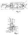
- Figure 3 shows a plan view of the unmanned agricultural vehicle viewed in the direction of the arrow III in Figure 2;
- Figure 4 shows a front elevation of the unmanned agricultural vehicle viewed in the direction of the arrow IV in Figure 2;
-
- Figure 1 shows a plan view of an unmanned vehicle 1 with a
plough 2 therebehind which is engaged in ploughing aplot 3.Stationary transceiver installations 4 are installed at each of the four corners of theplot 3. Each of thesetransceiver installations 4 is capable of cooperating with atransceiver installation 5 which is fitted to the unmanned vehicle 1. With the aid of thestationary transceiver installation 4 and thetransceiver installation 5 fitted to the unmanned agricultural vehicle, the position of the unmanned vehicle 1 on the plot can be very accurately determined. - The unmanned agricultural vehicle 1 is further provided with a monitoring system including sensors, with the aid of which a check can be made or intervention can be resorted to if, during operation, the unmanned vehicle 1 or an agricultural implement supported or towed thereby does not function in accordance with the requirements therefor. Notification of such malfunctioning of the vehicle and/or the agricultural implement is then transmitted by means of the
transceiver installation 5 to a (non-shown) mobile transceiver installation whereby the attention of the supervisor is drawn to the malfunctioning of the vehicle and/or the agricultural implement. The supervisor can issue instructions to the vehicle 1 or the agricultural implement via the mobile transceiver installation. A firstrotatable camera 6 is mounted close to the front of the vehicle 1 with the aid of which images from the front of the vehicle 1 can be collected. Via thetransceiver installation 5 the images are transmitted to the supervisor's mobile transceiver installation, whereupon the supervisor can view the images on a viewing screen. Centre-rear of the vehicle 1 a substantially vertical telescopically extendable standard 7 is fitted and on the extremity of which a second rotatablypivotable camera 8 is also fitted. By means of thesecond camera 8 images are likewise collected from the area around the vehicle 1. A rotatable telemeter 9 is also fitted to the extremity of the standard 7 and with the aid of which the distance to certain objects somewhere around the vehicle 1 can be determined. In the event of there being a strange object at a specific distance from the vehicle 1 and by which the progress of the latter may be impeded, the monitoring system automatically puts the control system of the vehicle 1 out of operation so that it comes to a stop added to which the monitoring system informs the supervisor of the incident. By means of the images recorded by the camera the supervisor is able to pass instructions via the mobile transceiver installation so that the obstruction can be avoided. - Furthermore, a pendulum arm 10 is fitted to the front side of the vehicle 1, which pendulum arm 10 is rotatable about a substantially horizontal axis 11 and is provided with a
counterweight 12 on its lower side. Because of the action of thecounterweight 12 and the freely pivoting pendulum arm 10, the latter remains substantially vertical irrespective of the angle-of-slope adopted by the vehicle 1. In the shaft 11 there is provided a (non-shown) clinometer by means of which the angle-of-slope of the vehicle with respect to the horizontal plane can be determined. In the presently described embodiment of the invention, the clinometer comprises a potentiometer. The pendulum arm 10 further comprises anantenna 13 of thetransceiver installation 5 close to its upper side. The monitoring system further comprises acomputer 15 accommodated in thecabin 14 of the vehicle 1. Thecomputer 15 is programmed with an adjustable threshold value for the angle-of-slope of the vehicle together with alarming means which warn the supervisor if the threshold value is exceeded. In the event of a signal being given by the clinometer that the threshold value has been exceeded, then a vehicle-control blocking system is activated to put the control system of the vehicle out of operation, whereafter the vehicle is stopped. The supervisor is warned of the incident via the alarming means, whereafter he is enabled to intervene. - The vehicle 1 is further provided with
sensors 16 on both sides close to the front and rear sides and the centre with the aid of which the distance to the ground can be measured. By means of thesensors 16, for example, it is possible to determine during ploughing whether the ploughed furrow has the required depth. If the measured depth deviates from the required depth, then the supervisor is informed thereof via thetransceiver installation 5. The supervisor can then remotely control a hydraulic plough adjuster in order that the required depth is achieved. - In the
computer 15, by means of a coding system, aplot 3 is split intorectangular areas 17 each of which areas is provided with a unique distinguishing code, see Figure 1. If a fault is reported, the supervisor is enabled to determine exactly in which of theareas 17 the vehicle 1 is located.
Claims (6)
- An unmanned agricultural vehicle (1), such as a tractor, provided with a transceiver installation (5) which is arranged to cooperate with a stationary transceiver installation (4) and/or with a satellite-navigation system, such as GPS, the vehicle (1) being provided with a monitoring system including sensors, with the aid of which a check can be made or intervention can be resorted to if, during operation, the unmanned vehicle (1) and/or an agricultural implement supported or towed thereby do/does not function in accordance with the requirements therefor, characterized in that the monitoring system of the vehicle (1) is provided with sensors (16) on both sides of the vehicle close to the front and rear sides and in the centre thereof and with the aid of which the distance to the ground can be measured, in that the monitoring system is provided with a computer (15) which, after receiving signals from the sensors (16), is designed to transmit via the transceiver-installation (5) a signal to a mobile transceiver-installation of a supervisor if the measured depth deviates from a required depth.
- An unmanned vehicle as claimed in claim 1, characterized in that the monitoring system is provided with a computer (15) which, after having received signals from the sensors (16), transmits a signal to the control system of the vehicle (1) in order to stop the vehicle (1).
- An unmanned vehicle as claimed in claim 2, characterized in that the computer (15) is designed to give a warning to the mobile transceiver-installation of the supervisor via the transceiver- installation (5) in the event of an interruption occurring.
- An unmanned vehicle as claimed in any one of the preceding claims, characterized in that the mobile transceiver installation of the supervisor is adapted to issue instructions to the vehicle (1) and/or the agricultural implement.
- An unmanned vehicle as claimed in claim 4, characterized in that the vehicle (1) is provided with a hydraulic plough adjuster, which is adapted to be remotely operated by the supervisor via the mobile transceiver-installation.
- An unmanned vehicle as claimed in any one of the preceding claims, characterized in that the mobile transceiver-installation of the supervisor comprises optical and/or acoustical means with the aid of which the supervisor is given a warning.
Priority Applications (1)
| Application Number | Priority Date | Filing Date | Title |
|---|---|---|---|
| EP97936882A EP0857325B1 (en) | 1996-08-29 | 1997-08-21 | An unmanned vehicle |
Applications Claiming Priority (4)
| Application Number | Priority Date | Filing Date | Title |
|---|---|---|---|
| EP96202396 | 1996-08-29 | ||
| EP96202396 | 1996-08-29 | ||
| EP97936882A EP0857325B1 (en) | 1996-08-29 | 1997-08-21 | An unmanned vehicle |
| PCT/NL1997/000475 WO1998009207A1 (en) | 1996-08-29 | 1997-08-21 | An unmanned vehicle |
Publications (2)
| Publication Number | Publication Date |
|---|---|
| EP0857325A1 EP0857325A1 (en) | 1998-08-12 |
| EP0857325B1 true EP0857325B1 (en) | 2002-05-02 |
Family
ID=8224322
Family Applications (1)
| Application Number | Title | Priority Date | Filing Date |
|---|---|---|---|
| EP97936882A Expired - Lifetime EP0857325B1 (en) | 1996-08-29 | 1997-08-21 | An unmanned vehicle |
Country Status (7)
| Country | Link |
|---|---|
| EP (1) | EP0857325B1 (en) |
| JP (1) | JPH11514533A (en) |
| AT (1) | ATE217101T1 (en) |
| AU (1) | AU730370B2 (en) |
| DE (1) | DE69712303T2 (en) |
| DK (1) | DK0857325T3 (en) |
| WO (1) | WO1998009207A1 (en) |
Cited By (6)
| Publication number | Priority date | Publication date | Assignee | Title |
|---|---|---|---|---|
| CN107783539A (en) * | 2017-10-25 | 2018-03-09 | 上海联适导航技术有限公司 | Four-wheel carrier servomechanism and its control method based on Beidou satellite navigation |
| WO2021089813A2 (en) | 2019-11-08 | 2021-05-14 | Kverneland Group Operations Norway As | System for measuring and interpreting a force |
| US20210267121A1 (en) * | 2020-02-27 | 2021-09-02 | Cnh Industrial America Llc | Cut quality detection system for an agricultural mower |
| EP3905155A1 (en) | 2020-04-30 | 2021-11-03 | Kverneland Group Operations Norway AS | Machine learning applications in agriculture |
| EP3905109A1 (en) | 2020-04-30 | 2021-11-03 | Kverneland Group Operations Norway AS | System for controlling agricultural operations by optical means |
| EP3905110A1 (en) | 2020-04-30 | 2021-11-03 | Kverneland Group Operations Norway AS | System for controlling agricultural operations by optical means |
Families Citing this family (8)
| Publication number | Priority date | Publication date | Assignee | Title |
|---|---|---|---|---|
| FR2789770B1 (en) * | 1999-02-12 | 2001-03-23 | Gtm Construction | IMPLEMENTATION METHOD USING A GLOBAL POSITIONING SYSTEM |
| JP4126350B2 (en) * | 1999-04-20 | 2008-07-30 | 井関農機株式会社 | Paddy field machine |
| US7317977B2 (en) | 2004-08-23 | 2008-01-08 | Topcon Positioning Systems, Inc. | Dynamic stabilization and control of an earthmoving machine |
| JP6949162B2 (en) * | 2016-07-22 | 2021-10-13 | 株式会社クボタ | Work platform |
| US9989835B1 (en) | 2017-02-09 | 2018-06-05 | Cnh Industrial America Llc | System and method for mounting a camera on a work vehicle |
| JP6847026B2 (en) * | 2017-12-18 | 2021-03-24 | 株式会社クボタ | Tractor |
| JP7076706B2 (en) * | 2018-06-29 | 2022-05-30 | 株式会社クボタ | Working machine |
| JP7247240B2 (en) * | 2021-02-05 | 2023-03-28 | ヤンマーパワーテクノロジー株式会社 | Automated driving system for work vehicles |
Citations (3)
| Publication number | Priority date | Publication date | Assignee | Title |
|---|---|---|---|---|
| FR2583871A1 (en) * | 1985-06-21 | 1986-12-26 | Armef | Safety device intended to prevent the lateral overturning of a machine such as a forestry tractor or the like |
| DE4339600A1 (en) * | 1993-11-20 | 1995-05-24 | Kloeckner Humboldt Deutz Ag | Agricultural or earthmoving vehicle with optical monitoring of working tool |
| US5610815A (en) * | 1989-12-11 | 1997-03-11 | Caterpillar Inc. | Integrated vehicle positioning and navigation system, apparatus and method |
Family Cites Families (9)
| Publication number | Priority date | Publication date | Assignee | Title |
|---|---|---|---|---|
| US4657087A (en) * | 1983-02-07 | 1987-04-14 | Zvi Livneh | Vehicle control system including vehicle with steering and elevation control relative to a filament |
| WO1991009375A1 (en) * | 1989-12-11 | 1991-06-27 | Caterpillar Inc. | Integrated vehicle positioning and navigation system, apparatus and method |
| US5111401A (en) * | 1990-05-19 | 1992-05-05 | The United States Of America As Represented By The Secretary Of The Navy | Navigational control system for an autonomous vehicle |
| NL9201215A (en) * | 1992-07-08 | 1994-02-01 | Texas Industries Inc | VEHICLE. |
| US5314037A (en) * | 1993-01-22 | 1994-05-24 | Shaw David C H | Automobile collision avoidance system |
| US5350033A (en) * | 1993-04-26 | 1994-09-27 | Kraft Brett W | Robotic inspection vehicle |
| US5530330A (en) * | 1994-03-30 | 1996-06-25 | Inco Limited | Automated guidance system for a vehicle |
| DE4434789A1 (en) * | 1994-09-29 | 1996-04-04 | Dieter Dipl Phys Dr Zwingel | GPS (Global positioning system)-supported safety system for roads |
| JP3524605B2 (en) * | 1994-12-13 | 2004-05-10 | 西松建設株式会社 | Unmanned unloading vehicle and unmanned unloading measurement method |
-
1997
- 1997-08-21 EP EP97936882A patent/EP0857325B1/en not_active Expired - Lifetime
- 1997-08-21 WO PCT/NL1997/000475 patent/WO1998009207A1/en not_active Ceased
- 1997-08-21 DK DK97936882T patent/DK0857325T3/en active
- 1997-08-21 AT AT97936882T patent/ATE217101T1/en not_active IP Right Cessation
- 1997-08-21 AU AU39541/97A patent/AU730370B2/en not_active Ceased
- 1997-08-21 JP JP10511499A patent/JPH11514533A/en active Pending
- 1997-08-21 DE DE69712303T patent/DE69712303T2/en not_active Expired - Lifetime
Patent Citations (3)
| Publication number | Priority date | Publication date | Assignee | Title |
|---|---|---|---|---|
| FR2583871A1 (en) * | 1985-06-21 | 1986-12-26 | Armef | Safety device intended to prevent the lateral overturning of a machine such as a forestry tractor or the like |
| US5610815A (en) * | 1989-12-11 | 1997-03-11 | Caterpillar Inc. | Integrated vehicle positioning and navigation system, apparatus and method |
| DE4339600A1 (en) * | 1993-11-20 | 1995-05-24 | Kloeckner Humboldt Deutz Ag | Agricultural or earthmoving vehicle with optical monitoring of working tool |
Cited By (8)
| Publication number | Priority date | Publication date | Assignee | Title |
|---|---|---|---|---|
| CN107783539A (en) * | 2017-10-25 | 2018-03-09 | 上海联适导航技术有限公司 | Four-wheel carrier servomechanism and its control method based on Beidou satellite navigation |
| WO2021089813A2 (en) | 2019-11-08 | 2021-05-14 | Kverneland Group Operations Norway As | System for measuring and interpreting a force |
| US12150401B2 (en) | 2019-11-08 | 2024-11-26 | Kubota Corporation | System for measuring and interpreting a force |
| US20210267121A1 (en) * | 2020-02-27 | 2021-09-02 | Cnh Industrial America Llc | Cut quality detection system for an agricultural mower |
| US11672198B2 (en) * | 2020-02-27 | 2023-06-13 | Cnh Industrial America Llc | Cut quality detection system for an agricultural mower |
| EP3905155A1 (en) | 2020-04-30 | 2021-11-03 | Kverneland Group Operations Norway AS | Machine learning applications in agriculture |
| EP3905109A1 (en) | 2020-04-30 | 2021-11-03 | Kverneland Group Operations Norway AS | System for controlling agricultural operations by optical means |
| EP3905110A1 (en) | 2020-04-30 | 2021-11-03 | Kverneland Group Operations Norway AS | System for controlling agricultural operations by optical means |
Also Published As
| Publication number | Publication date |
|---|---|
| DE69712303D1 (en) | 2002-06-06 |
| JPH11514533A (en) | 1999-12-14 |
| DK0857325T3 (en) | 2002-08-19 |
| AU730370B2 (en) | 2001-03-08 |
| ATE217101T1 (en) | 2002-05-15 |
| EP0857325A1 (en) | 1998-08-12 |
| AU3954197A (en) | 1998-03-19 |
| DE69712303T2 (en) | 2002-12-12 |
| WO1998009207A1 (en) | 1998-03-05 |
Similar Documents
| Publication | Publication Date | Title |
|---|---|---|
| EP0857325B1 (en) | An unmanned vehicle | |
| KR102678029B1 (en) | Autonomous travelling service vehicle | |
| US11556132B2 (en) | Work vehicle | |
| US9836059B2 (en) | Autonomous travel working vehicle | |
| KR102493698B1 (en) | work car | |
| EP3567396B1 (en) | Work vehicle | |
| JP7447927B2 (en) | work vehicle | |
| US20170135277A1 (en) | Autonomously traveling work vehicle | |
| US6222457B1 (en) | Electronic trailer hitching system | |
| JP3470947B2 (en) | Connection alignment warning system | |
| JP6615823B2 (en) | Work vehicle | |
| EP3959954B1 (en) | Harvester, obstacle determination program, recording medium on which obstacle determination program is recorded, obstacle determination method, agricultural work machine, control program, recording medium on which control program is recorded, and control method | |
| US20210000007A1 (en) | Work Vehicle | |
| EP3579022A1 (en) | Laser radar for work vehicle | |
| JP2025171070A (en) | Work vehicles | |
| CN217902037U (en) | Automatic driving vehicle detection system | |
| JP2021193899A (en) | Work vehicle | |
| RU2830977C2 (en) | Obstacle detection system for agricultural machinery | |
| JP7677104B2 (en) | Work vehicle condition judgment system | |
| US20240119842A1 (en) | Methods and Systems for Coupling Vehicles | |
| JP2025101176A (en) | Work vehicles | |
| JP2025120765A (en) | Work vehicles | |
| JP2024093157A (en) | Self-driving agricultural vehicle | |
| JP2018184099A (en) | Working vehicle |
Legal Events
| Date | Code | Title | Description |
|---|---|---|---|
| PUAI | Public reference made under article 153(3) epc to a published international application that has entered the european phase |
Free format text: ORIGINAL CODE: 0009012 |
|
| 17P | Request for examination filed |
Effective date: 19980508 |
|
| AK | Designated contracting states |
Kind code of ref document: A1 Designated state(s): AT BE CH DE DK FR GB IE IT LI NL SE |
|
| 17Q | First examination report despatched |
Effective date: 20000420 |
|
| GRAG | Despatch of communication of intention to grant |
Free format text: ORIGINAL CODE: EPIDOS AGRA |
|
| GRAG | Despatch of communication of intention to grant |
Free format text: ORIGINAL CODE: EPIDOS AGRA |
|
| GRAH | Despatch of communication of intention to grant a patent |
Free format text: ORIGINAL CODE: EPIDOS IGRA |
|
| REG | Reference to a national code |
Ref country code: GB Ref legal event code: IF02 |
|
| GRAH | Despatch of communication of intention to grant a patent |
Free format text: ORIGINAL CODE: EPIDOS IGRA |
|
| GRAA | (expected) grant |
Free format text: ORIGINAL CODE: 0009210 |
|
| AK | Designated contracting states |
Kind code of ref document: B1 Designated state(s): AT BE CH DE DK FR GB IE IT LI NL SE |
|
| REF | Corresponds to: |
Ref document number: 217101 Country of ref document: AT Date of ref document: 20020515 Kind code of ref document: T |
|
| REG | Reference to a national code |
Ref country code: GB Ref legal event code: FG4D |
|
| REG | Reference to a national code |
Ref country code: CH Ref legal event code: EP |
|
| REF | Corresponds to: |
Ref document number: 69712303 Country of ref document: DE Date of ref document: 20020606 |
|
| REG | Reference to a national code |
Ref country code: IE Ref legal event code: FG4D |
|
| PGFP | Annual fee paid to national office [announced via postgrant information from national office to epo] |
Ref country code: SE Payment date: 20020801 Year of fee payment: 6 Ref country code: AT Payment date: 20020801 Year of fee payment: 6 |
|
| PGFP | Annual fee paid to national office [announced via postgrant information from national office to epo] |
Ref country code: CH Payment date: 20020802 Year of fee payment: 6 |
|
| PGFP | Annual fee paid to national office [announced via postgrant information from national office to epo] |
Ref country code: DK Payment date: 20020805 Year of fee payment: 6 |
|
| REG | Reference to a national code |
Ref country code: CH Ref legal event code: NV Representative=s name: PATENTANWALTSBUERO EDER AG |
|
| REG | Reference to a national code |
Ref country code: DK Ref legal event code: T3 |
|
| PGFP | Annual fee paid to national office [announced via postgrant information from national office to epo] |
Ref country code: IE Payment date: 20020828 Year of fee payment: 6 |
|
| PGFP | Annual fee paid to national office [announced via postgrant information from national office to epo] |
Ref country code: BE Payment date: 20020904 Year of fee payment: 6 |
|
| PLBE | No opposition filed within time limit |
Free format text: ORIGINAL CODE: 0009261 |
|
| STAA | Information on the status of an ep patent application or granted ep patent |
Free format text: STATUS: NO OPPOSITION FILED WITHIN TIME LIMIT |
|
| 26N | No opposition filed |
Effective date: 20030204 |
|
| PGFP | Annual fee paid to national office [announced via postgrant information from national office to epo] |
Ref country code: GB Payment date: 20030813 Year of fee payment: 7 |
|
| PG25 | Lapsed in a contracting state [announced via postgrant information from national office to epo] |
Ref country code: IE Free format text: LAPSE BECAUSE OF NON-PAYMENT OF DUE FEES Effective date: 20030821 Ref country code: AT Free format text: LAPSE BECAUSE OF NON-PAYMENT OF DUE FEES Effective date: 20030821 |
|
| PG25 | Lapsed in a contracting state [announced via postgrant information from national office to epo] |
Ref country code: SE Free format text: LAPSE BECAUSE OF NON-PAYMENT OF DUE FEES Effective date: 20030822 |
|
| PG25 | Lapsed in a contracting state [announced via postgrant information from national office to epo] |
Ref country code: LI Free format text: LAPSE BECAUSE OF NON-PAYMENT OF DUE FEES Effective date: 20030831 Ref country code: CH Free format text: LAPSE BECAUSE OF NON-PAYMENT OF DUE FEES Effective date: 20030831 Ref country code: BE Free format text: LAPSE BECAUSE OF NON-PAYMENT OF DUE FEES Effective date: 20030831 |
|
| PG25 | Lapsed in a contracting state [announced via postgrant information from national office to epo] |
Ref country code: DK Free format text: LAPSE BECAUSE OF NON-PAYMENT OF DUE FEES Effective date: 20030901 |
|
| BERE | Be: lapsed |
Owner name: *MAASLAND N.V. Effective date: 20030831 |
|
| EUG | Se: european patent has lapsed | ||
| REG | Reference to a national code |
Ref country code: DK Ref legal event code: EBP |
|
| REG | Reference to a national code |
Ref country code: CH Ref legal event code: PL |
|
| REG | Reference to a national code |
Ref country code: IE Ref legal event code: MM4A |
|
| PG25 | Lapsed in a contracting state [announced via postgrant information from national office to epo] |
Ref country code: GB Free format text: LAPSE BECAUSE OF NON-PAYMENT OF DUE FEES Effective date: 20040821 |
|
| GBPC | Gb: european patent ceased through non-payment of renewal fee |
Effective date: 20040821 |
|
| PG25 | Lapsed in a contracting state [announced via postgrant information from national office to epo] |
Ref country code: IT Free format text: LAPSE BECAUSE OF NON-PAYMENT OF DUE FEES Effective date: 20050821 |
|
| PGFP | Annual fee paid to national office [announced via postgrant information from national office to epo] |
Ref country code: NL Payment date: 20100824 Year of fee payment: 14 |
|
| PGFP | Annual fee paid to national office [announced via postgrant information from national office to epo] |
Ref country code: FR Payment date: 20100831 Year of fee payment: 14 Ref country code: DE Payment date: 20100827 Year of fee payment: 14 |
|
| REG | Reference to a national code |
Ref country code: NL Ref legal event code: V1 Effective date: 20120301 |
|
| REG | Reference to a national code |
Ref country code: FR Ref legal event code: ST Effective date: 20120430 |
|
| PG25 | Lapsed in a contracting state [announced via postgrant information from national office to epo] |
Ref country code: NL Free format text: LAPSE BECAUSE OF NON-PAYMENT OF DUE FEES Effective date: 20120301 |
|
| REG | Reference to a national code |
Ref country code: DE Ref legal event code: R119 Ref document number: 69712303 Country of ref document: DE Effective date: 20120301 |
|
| PG25 | Lapsed in a contracting state [announced via postgrant information from national office to epo] |
Ref country code: FR Free format text: LAPSE BECAUSE OF NON-PAYMENT OF DUE FEES Effective date: 20110831 |
|
| PG25 | Lapsed in a contracting state [announced via postgrant information from national office to epo] |
Ref country code: DE Free format text: LAPSE BECAUSE OF NON-PAYMENT OF DUE FEES Effective date: 20120301 |