EP0856739B1 - Method for detecting short-circuit conditions and device which uses this method - Google Patents
Method for detecting short-circuit conditions and device which uses this method Download PDFInfo
- Publication number
- EP0856739B1 EP0856739B1 EP97203862A EP97203862A EP0856739B1 EP 0856739 B1 EP0856739 B1 EP 0856739B1 EP 97203862 A EP97203862 A EP 97203862A EP 97203862 A EP97203862 A EP 97203862A EP 0856739 B1 EP0856739 B1 EP 0856739B1
- Authority
- EP
- European Patent Office
- Prior art keywords
- circuit
- short
- network
- current
- load
- Prior art date
- Legal status (The legal status is an assumption and is not a legal conclusion. Google has not performed a legal analysis and makes no representation as to the accuracy of the status listed.)
- Expired - Lifetime
Links
Images

Classifications
-
- H—ELECTRICITY
- H02—GENERATION; CONVERSION OR DISTRIBUTION OF ELECTRIC POWER
- H02H—EMERGENCY PROTECTIVE CIRCUIT ARRANGEMENTS
- H02H3/00—Emergency protective circuit arrangements for automatic disconnection directly responsive to an undesired change from normal electric working condition with or without subsequent reconnection ; integrated protection
- H02H3/44—Emergency protective circuit arrangements for automatic disconnection directly responsive to an undesired change from normal electric working condition with or without subsequent reconnection ; integrated protection responsive to the rate of change of electrical quantities
-
- G—PHYSICS
- G01—MEASURING; TESTING
- G01R—MEASURING ELECTRIC VARIABLES; MEASURING MAGNETIC VARIABLES
- G01R31/00—Arrangements for testing electric properties; Arrangements for locating electric faults; Arrangements for electrical testing characterised by what is being tested not provided for elsewhere
- G01R31/50—Testing of electric apparatus, lines, cables or components for short-circuits, continuity, leakage current or incorrect line connections
- G01R31/52—Testing for short-circuits, leakage current or ground faults
Definitions
- the present invention relates to a method able rapidly to detect the initiating of short-circuit conditions in an electrical network, as well as to a device which uses this method.
- the objective of the present invention is to solve the technical problem illustrated above, by overcoming the limitations of the prior art, and in particular to carry out the rapid detection of short-circuit conditions in a network, with simultaneous calculation of the value of the power factor of the short-circuit (cos ⁇ ) and of the phase of the voltage at the moment of the short-circuit.
- the invention relates, moreover, to a device for detecting short-circuit conditions in an electrical network comprising at least one voltage source connected to at least one load, the said device being characterized in that it comprises:
- the invention relates, moreover, to a device for detecting short-circuit conditions in an electrical network comprising at least one voltage source connected to at least one load, the said device being characterized in that it comprises a digital/analogue converter which receives as input a signal proportional to the instantaneous current i(t), a digital differentiator (or filter) connected to the output of said converter, and processing and detection means, connected to the outputs of said converters and digital differentiator, said means being able to output a signal representative of the short-circuit conditions C.
- the detection of short-circuit conditions is based on estimating the electrical characteristics of the load under short-circuit conditions, and more particularly its impedance.
- the peak value of the current is typically calculated from this, before the current actually attains the said peak value. If this value is greater than a desired threshold Icc, then the fault is detectd as a short-circuit.
- treshold value Icc depends upon the value of cos ⁇ .
- the method according to the invention makes it possible to achieve detection very rapidly, typically in a few milliseconds.
- the method according to the invention makes it possible concurrently to determine other characteristics of the circuit at the moment of the fault, such as the value of the power factor of the short-circuit (cos ⁇ ) and the phase of the voltage at the moment of the short-circuit.
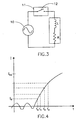
- the electrical network whereto the invention is applied is represented by means of a voltage source 10, and a load having a reactive component L (of inductive type) and a resistive component R.
- the source 10 is for example a sinusoidal generator (V) of known frequency (for example 50 Hz) and known peak value (for example 220 x ⁇ 2 volt).
- the source 10 illustrated in Figure 3 as a voltage generator, is in reality a schematization of different sources and generators present in the network.
- the network can be a single-phase, three-phase or in general a polyphase network.
- the device according to the invention is represented by means of a block 11 provided with a circuit breaker 12 inserted in series between the generator 10 and load (i.e. the rest of the network).
- the opening of the circuit breaker is controlled by circuitry (not shown) which comprises suitable sensors and which uses the method of the invention to detect a possible short-circuit condition.
- the method of the invention provides for the definition of a first "guard" threshold level indicated Is.
- the method does not provide for such a constraint, and passes directly to the phases described below continuatively and/or periodically, starting from the instant at which the network is powered, or following some other pre-established event(s).
- the guard threshold upon exceeding this threshold, which may constitute the beginning of a short-circuit or form part of a transient, a sampling is begun of successive values taken by the current, at pre-established intervals, for example those indicated by the times t1, t2, t3 etc. in Figure 4.
- the behaviour pattern of the current i(t) is reconstructed or predicted on the basis of these values, and the parameters of the load are derived from it. These parameters are then compared with reference values so as to establish whether a short-circuit is occurring. If there is no provision for the guard threshold, the sampling can be carried out continuosly.
- the detection of the short-circuit conditions i.e. when the threshold peak current is > Icc
- the proposed method is capable of estimating or forecasting in advance - based on previously stored values - the behaviour pattern of the current, and hence the imminent exceeding of the threshold Icc.
- the method of the invention nevertheless makes it possible to obtain information about this short-circuit.
- the estimate of the behaviour pattern of the current from the samples is obtained by the least squares method and using normalized values of the current for simplicity of processing.
- Figure 3 is an equivalent representation ("Thevenin equivalent") of the electrical network considered, so that the components 10, R, L are not necessarily physical components, but the "equivalent generator” and the “equivalent load” viewed by the device 11.
- N Tr/Dt
- the vector ⁇ ' is the transposed of the vector
- ki* ( ⁇ *2 + ⁇ * 2 )/(1 + ⁇ * 2 )] 1/2
- the value ki* is compared with the threshold k0.
- Figure 1 illustrates an embodiment of the device according to the invention which comprises an appropriate analogue differentiator filter 1 which calculates the instantaneous derivative of the current.
- the analogue differentiator 1 receives as input a signal proportional to the instantaneous current i(t), for example via the sensor 5, and delivers as output a signal which represents the first derivative thereof, i.e. "di(t)/dt".
- the device moreover comprises two analogue/digital converters, 2 and 3 respectively, which convert into digital form the signal i(t) and its derivative output by the differentiator 1.
- the outputs from the converters are fed to the processing and detection block 4 which, using the method of the invention, detects the short-circuit and outputs a signal C, as well as the signals cos ⁇ and 0 which are representative of the angular phase and of the angle of extinction.
- the processing in the block 4 is executed by means of a programmed microprocessor system, although it is possible to use analogous discrete devices, either analogue or digital.
Landscapes
- Physics & Mathematics (AREA)
- General Physics & Mathematics (AREA)
- Emergency Protection Circuit Devices (AREA)
- Monitoring And Testing Of Exchanges (AREA)
- Testing Of Short-Circuits, Discontinuities, Leakage, Or Incorrect Line Connections (AREA)
Description
- The present invention relates to a method able rapidly to detect the initiating of short-circuit conditions in an electrical network, as well as to a device which uses this method.
- The invention will be illustrated with particular reference to a preferred application in a low-voltage electrical power distribution network, although this is not to be understood as limiting, and in any event the invention applies in general to both medium and low-voltage networks.
- In modern automatic circuit breakers for low and medium voltage, devices for detecting faults are integrated in the circuit breakers, and such detection of faults is often performed by means of devices of electronic type.
- However, the detection of short-circuits, characterized by very high current and by the need for very rapid actuation so as to eliminate the fault, is still carried out at the present time by electromechanical devices based on the electrodynamic effect.
- The calibration of these short-circuit detection devices is very difficult and is carried out on an empirical basis. This leads to low accuracy in the determination of the actuation times of the circuit breaker.
- Moreover, with these electromechanical devices it is not possible to gather, in the case of a short-circuit fault, detailed information about the fault such as, for example, the peak current characterizing the fault, the complex impedance of the circuit or the angle of the voltage at the moment of extinction of the fault. This information would be useful among other things for diagnostic and statistical purposes.
- Finally, in an automatic circuit breaker based on the known short-circuit detection mechanism, it is not possible to prevent the opening of the circuit breaker once the fault has been detectd. However, in many situations, such as for example when the circuit breaker is part of a power distribution network which comprises other circuit breakers, it is desirable for just one of them to open the circuit, even if the fault was detected by several circuit breakers simultaneously.
- Examples of known methods and devices are given in DE-A-4 111 831 and DE-A-4 429 191.
- There is therefore a technical need to make available a circuit breaker device which is capable of detecting a short-circuit fault without necessarily involving the opening of said circuit breaker, since the opening operation may be subject to other parameters and/or assigned to other circuit breakers present in the network.
- The objective of the present invention is to solve the technical problem illustrated above, by overcoming the limitations of the prior art, and in particular to carry out the rapid detection of short-circuit conditions in a network, with simultaneous calculation of the value of the power factor of the short-circuit (cosϕ) and of the phase of the voltage at the moment of the short-circuit.
- These objectives are achieved by means of the invention which relates to a method for detecting short-circuit conditions in an electrical network comprising at least one voltage source connected to at least one load, characterized in that it comprises the following operational phases:
- a) measuring the values of the instantaneous current i(t) flowing in the load and of its first derivative di(t)/dt;
- b) performing N successive samplings of the values of the instantaneous current i(t);
- c) estimating the effective value of the load R, L viewed by the said source;
- d) generating a short-circuit detection signal C when the value of the estimated load is such as to cause the steady peak current to exceed an assigned threshold level Icc.
-
- The invention relates, moreover, to a device for detecting short-circuit conditions in an electrical network comprising at least one voltage source connected to at least one load, the said device being characterized in that it comprises:
- an analogue differentiator which receives as input a signal proportional to the instantaneous current i(t) and delivers as output a signal which represents the first derivative di(t)/dt thereof;
- two analogue/digital converters whose inputs are connected to the said signal i(t) and to the output of the said differentiator; and
- processing and detection means connected to the outputs of the said converters and able to output a signal representative of the short-circuit conditions C.
-
- The invention relates, moreover, to a device for detecting short-circuit conditions in an electrical network comprising at least one voltage source connected to at least one load, the said device being characterized in that it comprises a digital/analogue converter which receives as input a signal proportional to the instantaneous current i(t), a digital differentiator (or filter) connected to the output of said converter, and processing and detection means, connected to the outputs of said converters and digital differentiator, said means being able to output a signal representative of the short-circuit conditions C.
- According to the invention, the detection of short-circuit conditions is based on estimating the electrical characteristics of the load under short-circuit conditions, and more particularly its impedance. The peak value of the current is typically calculated from this, before the current actually attains the said peak value. If this value is greater than a desired threshold Icc, then the fault is detectd as a short-circuit.
- Alternatively, more complex fault conditions can be defined, in which the treshold value Icc depends upon the value of cosϕ.
- The method according to the invention makes it possible to achieve detection very rapidly, typically in a few milliseconds.
- Advantageously, the method according to the invention makes it possible concurrently to determine other characteristics of the circuit at the moment of the fault, such as the value of the power factor of the short-circuit (cosϕ) and the phase of the voltage at the moment of the short-circuit.
- The invention will now be described with reference to the appended drawings relating to its preferred but non-limiting embodiments, in which:
- Figure 1 schematically illustrates a structure of the detection device according to the invention;
- Figure 2 illustrates an other embodiment of the device;
- Figure 3 is a schematic representation of a network for illustrating the principles of the invention; and
- Figure 4 is a graph which illustrates the pattern of behaviour of short-circuit conditions.
-
- The basic principles of the method according to the invention will firstly be illustrated with reference to Figure 3.
- In this figure, the electrical network whereto the invention is applied is represented by means of a
voltage source 10, and a load having a reactive component L (of inductive type) and a resistive component R. Thesource 10 is for example a sinusoidal generator (V) of known frequency (for example 50 Hz) and known peak value (for example 220 x √2 volt). - It should be stressed that the
source 10, illustrated in Figure 3 as a voltage generator, is in reality a schematization of different sources and generators present in the network. The network can be a single-phase, three-phase or in general a polyphase network. - The device according to the invention is represented by means of a
block 11 provided with acircuit breaker 12 inserted in series between thegenerator 10 and load (i.e. the rest of the network). The opening of the circuit breaker is controlled by circuitry (not shown) which comprises suitable sensors and which uses the method of the invention to detect a possible short-circuit condition. - With reference also to Figure 4, according to an alternative embodiment, the method of the invention provides for the definition of a first "guard" threshold level indicated Is. In other words, the instantaneous current i=i(t) flowing in the load is monitored and it is determined whether it exceeds a first threshold level. According to another more general form, the method does not provide for such a constraint, and passes directly to the phases described below continuatively and/or periodically, starting from the instant at which the network is powered, or following some other pre-established event(s).
- If there is provision for the guard threshold, upon exceeding this threshold, which may constitute the beginning of a short-circuit or form part of a transient, a sampling is begun of successive values taken by the current, at pre-established intervals, for example those indicated by the times t1, t2, t3 etc. in Figure 4. The behaviour pattern of the current i(t) is reconstructed or predicted on the basis of these values, and the parameters of the load are derived from it. These parameters are then compared with reference values so as to establish whether a short-circuit is occurring. If there is no provision for the guard threshold, the sampling can be carried out continuosly.
- It is important to note that, according to the invention, the detection of the short-circuit conditions (i.e. when the threshold peak current is > Icc) is not normally obtained from a measurement, since the proposed method is capable of estimating or forecasting in advance - based on previously stored values - the behaviour pattern of the current, and hence the imminent exceeding of the threshold Icc. Even when, in the case of a very fast short-circuit transient, detection is carried out with a very short or practically zero advance, the method of the invention nevertheless makes it possible to obtain information about this short-circuit.
- According to a preferred embodiment, illustrated in detail below, the estimate of the behaviour pattern of the current from the samples is obtained by the least squares method and using normalized values of the current for simplicity of processing. The method for detecting a short-circuit according to the invention therefore provides for the following steps:
when the instantaneous value of the normalized current I(t) exceeds a normalized threshold value Is, i.e. Is=3, the behaviour of the normalized current I(t) is calculated. - In the circuit of Figure 3, the normalized current I(t) can be expressed by the following relation:
- ϕ = arctan (L/R)
- Io = normalization constant (typically the nominal current which characterizes the circuit breaker);
- Vo = nominal peak voltage (for example VO = 220√2 V)
- w = nominal angular frequency of the electrical network (e.g. 50 Hz), with w=2πf
- I(t) = i(t)/Io
- I'(t) = [di(t)/dt].(1/wIo)
- = phase of the voltage.
-
- The parameter ki is the ratio between the peak value which the current i(t) attains when steady and the value Io, and kiIo represents the peak value which the current will attain when steady. Ki can be exspressed as:
- It is clear from the above that in order to estimate the effective parameters of the circuit (R, L), it is enough to estimate the value of the parameter ki.
- The phase of the voltage is a parameter such that, having fixed the time origin, the time profile of the voltage v(t) of the
sinusoidal generator 10 of Figure 3 can be defined as: - As already indicated, Figure 3 is an equivalent representation ("Thevenin equivalent") of the electrical network considered, so that the
components 10, R, L are not necessarily physical components, but the "equivalent generator" and the "equivalent load" viewed by thedevice 11. - The parameter N can be determined as follows: if Dt is the duration of the sampling interval (for example 100 microseconds), and Tr is the time required for detection (for example 3 ms), then N can be expressed as:
- The
relation 1 can be expressed in the following vectorial form:and let Φ(t)' be the transposed vector of Φ(t).
- The vector ε' is the transposed of the vector

- The vector ε is calculated asand the elements of ε* are defined as:
 so that ki* is expressed by:
- The value ki* is compared with the threshold k0. Preferably, a short-circuit situation is defined as a condition in which the value ki exceeds a preset threshold ko, typically, but not exclusively ko = 12.
- If ki*>k0 then a short-circuit condition does exist; otherwise the method is reiterated from the step of monitoring the current. The sign * indicates that these are values obtained by estimation.
- From the vector ε indicated above it is also possible to calculate also the estimate cosϕ* of the parameter cosϕ and the estimate * of the parameter using the following formulae:
- As indicated previously, other alternative methods, such as that of the mean quadratic value (known in the art by the initials LMS), etc., may be employed to estimate the short-circuit current.
- Figure 1 illustrates an embodiment of the device according to the invention which comprises an appropriate
analogue differentiator filter 1 which calculates the instantaneous derivative of the current. - The
analogue differentiator 1 receives as input a signal proportional to the instantaneous current i(t), for example via the sensor 5, and delivers as output a signal which represents the first derivative thereof, i.e. "di(t)/dt". The device moreover comprises two analogue/digital converters, 2 and 3 respectively, which convert into digital form the signal i(t) and its derivative output by thedifferentiator 1. The outputs from the converters are fed to the processing anddetection block 4 which, using the method of the invention, detects the short-circuit and outputs a signal C, as well as the signals cos and 0 which are representative of the angular phase and of the angle of extinction. - Preferably, the processing in the
block 4 is executed by means of a programmed microprocessor system, although it is possible to use analogous discrete devices, either analogue or digital. - In the variant embodiment of Figure 2, on the other hand, in which the same references have been used for corresponding parts, there is provided an A/D converter 2 which receives as input the signal i(t), and a digital differentiator (or filter) 6 connected to the output of this converter. The outputs of the blocks 2 and 6 are then connected to the
block 4, in a manner analogous to the above. - The above description relates to single-phase systems, however the invention can be applied also to the detection of short-circuits in two-phase or three-phase systems. In the case of systems on several phases, the method is applied independently on the different phases.
- The invention has been described with reference to particular and preferred embodiments, however it is not limited to these embodiments, but embraces the variants and modifications covered by the following claims.
Claims (10)
- Method for detecting short-circuit conditions in an electrical network comprising at least one voltage source (10) connected to at least one load, characterized in that it comprises the following operational phases:a) measuring the values of the instantaneous current (i(t)) flowing in the load and of its first derivative (di(t)/(dt);b) performing N successive samplings of the values of the instantaneous current i(t);c) estimating the effective parameters of the circuit (R, L) viewed by the said source (10);d) generating a short-circuit detection signal (C) when the value of the estimated effective parameter is such as to cause the steady peak current to exceed an assigned threshold level (Icc).
- Method according to Claim 1, characterized in that the said phase (b) can be subject to the attaining, by the instantaneous value of the current i(t), of a further threshold (Is).
- Method according to Claim 1 or 2, characterized in that the number N of successive samples of the values of the instantaneous current i(t) is fixed and defined as N=Tr/Dt, where Tr is the time required for detection and Dt is the duration of the sampling interval.
- Method according to the claim 3, characterized in that the estimate of the said effective parameters of the circuit (R, L) is obtained by the least squares method.
- Method according to the preceding claims, characterized in that the said source (10) is a sinusoidal voltage generator.
- Device for detecting short-circuit conditions in an electrical network comprising at least one voltage source (10) connected to at least one load, the said device (11) being characterized in that it comprises:an analogue differentiator (1) which receives as input a signal proportional to the instantaneous current i(t) and delivers as output a signal which represents the first derivative (di(t)/dt thereof;two analogue/digital converters (2, 3) whose inputs are connected to receive said signal i(t) and the output of the said differentiator (1); and processing and detection means (4) connected to the outputs of said converters (2, 3) adapted to perform the phases c) and d) according to any of the claims from 1 to 5.
- Device for detecting short-circuit conditions in an electrical network comprising at least one voltage source (10) connected to at least one load, the said device (11) being characterized in that it comprises a digital/analogue converter (2) which receives as input a signal proportional to the instantaneous current i(t), a digital differentiator (6) connected to the output of said converter, and processing and detection means (4), connected to the outputs of said converters (2, 3), adapted to perform the phases c) and d) according to any of the claims from 1 to 5.
- Device according to Claims 6 or 7, characterized in that the said processing and detection means (4) are able additionally to output signals representative of the value of the power factor of the short-circuit (cosϕ) and the phase of the voltage at the moment of the short-circuit.
- Method according to Claim 2, characterized in that the said distribution network is a low or medium-voltage network.
- Method according to the claim 2, characterized in that the said network is a three-phase network, and the method is applied independently to each phase.
Applications Claiming Priority (3)
| Application Number | Priority Date | Filing Date | Title |
|---|---|---|---|
| IT1996MI002580A IT1305598B1 (en) | 1996-12-10 | 1996-12-10 | METHOD FOR THE RECOGNITION OF SHORT CIRCUIT CONDITIONS AND DEVICE THAT USES THIS METHOD |
| ITMI962580 | 1996-12-10 | ||
| US09/092,657 US6437576B2 (en) | 1996-12-10 | 1998-06-05 | Method for detecting short-circuit conditions and device which uses this method |
Publications (2)
| Publication Number | Publication Date |
|---|---|
| EP0856739A1 EP0856739A1 (en) | 1998-08-05 |
| EP0856739B1 true EP0856739B1 (en) | 2004-10-13 |
Family
ID=26331451
Family Applications (1)
| Application Number | Title | Priority Date | Filing Date |
|---|---|---|---|
| EP97203862A Expired - Lifetime EP0856739B1 (en) | 1996-12-10 | 1997-12-10 | Method for detecting short-circuit conditions and device which uses this method |
Country Status (3)
| Country | Link |
|---|---|
| US (1) | US6437576B2 (en) |
| EP (1) | EP0856739B1 (en) |
| IT (1) | IT1305598B1 (en) |
Families Citing this family (19)
| Publication number | Priority date | Publication date | Assignee | Title |
|---|---|---|---|---|
| JP3987950B2 (en) * | 2001-12-27 | 2007-10-10 | サンケン電気株式会社 | DC-DC converter |
| US7061252B2 (en) * | 2004-07-02 | 2006-06-13 | Hudson Respiratory Care, Inc. | Electrical arcing protection circuit |
| ITMI20071642A1 (en) * | 2007-08-07 | 2009-02-08 | Abb Service Srl | A PROCEDURE FOR THE MANAGEMENT OF A FAILURE EVENT IN A DISTRIBUTION NETWORK OF ELECTRICAL ENERGY AND A RELATED ELECTRONIC PROTECTION UNIT. |
| DE102007052963A1 (en) * | 2007-10-30 | 2009-05-14 | Siemens Ag | Method for short-circuit detection in an electrical power network |
| US8228068B2 (en) * | 2008-05-02 | 2012-07-24 | Siemens Aktiengesellschaft | Systems and methods for detecting wire breaks |
| WO2010133717A1 (en) * | 2009-05-20 | 2010-11-25 | Inael Electrical Systems, S.A. | Method for activating the counter of a sectionalizer |
| DE102010013322B4 (en) * | 2010-03-30 | 2011-11-17 | Austriamicrosystems Ag | Detection circuit and method for operating a detection circuit |
| CN103457247B (en) * | 2013-08-09 | 2015-10-14 | 福州大学 | The selectively coordinated resist technology of low-pressure system multi-layer gamut |
| US9236131B1 (en) | 2014-08-04 | 2016-01-12 | Sandisk Technologies Inc. | Bias to detect and prevent short circuits in three-dimensional memory device |
| US9230982B1 (en) | 2014-08-04 | 2016-01-05 | Sandisk Technologies Inc. | Protective structure to prevent short circuits in a three-dimensional memory device |
| JP6324629B2 (en) * | 2015-06-19 | 2018-05-16 | 三菱電機株式会社 | Leakage current detector |
| CN107294135B (en) * | 2017-07-06 | 2020-08-11 | 华北水利水电大学 | Self-adaptive current protection method for power grid with distributed power supply access |
| WO2020073201A1 (en) * | 2018-10-09 | 2020-04-16 | Abb Schweiz Ag | Method and system for circuit breaker condition monitoring |
| CN112736871B (en) * | 2020-12-24 | 2024-05-10 | 国网浙江省电力有限公司电力科学研究院 | Method and system for finely checking short-circuit current of transformer substation of 220kV and below |
| CN113078613B (en) * | 2021-04-08 | 2024-12-24 | 华侨大学 | Fast electrical fire protection current limiting protection device |
| WO2022247637A1 (en) * | 2021-05-26 | 2022-12-01 | 佛山市顺德区美的电子科技有限公司 | Fault detection method and apparatus, and device, system and storage medium |
| CN114039412A (en) * | 2021-09-27 | 2022-02-11 | 广东电网有限责任公司广州供电局 | Phase selection control method and device applied to high-voltage circuit breaker |
| DE102022128623A1 (en) * | 2022-10-28 | 2024-05-08 | Bayerische Motoren Werke Aktiengesellschaft | Method and protective device for protecting a device against a fault current and motor vehicle equipped accordingly |
| CN120870960B (en) * | 2025-09-26 | 2025-12-02 | 南京能瑞自动化设备股份有限公司 | Electricity safety processing method and system based on single-phase intelligent electric energy meter |
Family Cites Families (10)
| Publication number | Priority date | Publication date | Assignee | Title |
|---|---|---|---|---|
| US3599044A (en) * | 1970-04-30 | 1971-08-10 | Fuji Electric Co Ltd | Superhigh-speed relaying system and apparatus for protection of power systems |
| DE2247746C3 (en) * | 1972-09-29 | 1975-11-27 | Siemens Ag, 1000 Berlin Und 8000 Muenchen | Method of measuring a line impedance |
| US4150411A (en) * | 1977-12-15 | 1979-04-17 | General Electric Company | Ground fault circuit interrupter utilizing a single transformer |
| US4767996A (en) * | 1986-01-20 | 1988-08-30 | Kabushiki Kaisha Toshiba | Fault current detection device for a D.C. network |
| FR2598266B1 (en) * | 1986-04-30 | 1994-02-18 | Merlin Et Gerin | INSTANT STATIC TRIGGER FOR A LIMITING CIRCUIT BREAKER |
| DE3642136A1 (en) * | 1986-12-10 | 1988-06-23 | Licentia Gmbh | Electronic tripping device for switches (circuit breakers) which limit the short-circuit current |
| US5181155A (en) * | 1990-08-30 | 1993-01-19 | Beg Mirza A | Overcurrent trip circuit |
| DE4111831A1 (en) * | 1991-04-11 | 1992-10-15 | Abb Patent Gmbh | Release method for overcurrent protection switch - using measured current values and corresponding current gradients obtained by differentiation to trigger switch |
| US5537327A (en) * | 1993-10-22 | 1996-07-16 | New York State Electric & Gas Corporation | Method and apparatus for detecting high-impedance faults in electrical power systems |
| DE4429191A1 (en) * | 1994-08-18 | 1996-02-22 | Licentia Gmbh | Algorithm for modelling status changes e.g. in electrical power transmission networks |
-
1996
- 1996-12-10 IT IT1996MI002580A patent/IT1305598B1/en active
-
1997
- 1997-12-10 EP EP97203862A patent/EP0856739B1/en not_active Expired - Lifetime
-
1998
- 1998-06-05 US US09/092,657 patent/US6437576B2/en not_active Expired - Lifetime
Also Published As
| Publication number | Publication date |
|---|---|
| IT1305598B1 (en) | 2001-05-09 |
| ITMI962580A0 (en) | 1996-12-10 |
| ITMI962580A1 (en) | 1998-06-10 |
| US6437576B2 (en) | 2002-08-20 |
| US20020005721A1 (en) | 2002-01-17 |
| EP0856739A1 (en) | 1998-08-05 |
Similar Documents
| Publication | Publication Date | Title |
|---|---|---|
| EP0856739A1 (en) | Method for detecting short-circuit conditions and device which uses this method | |
| US4812995A (en) | Adaptive Kalman Filtering in fault classification | |
| FI115488B (en) | Method and apparatus for detecting a breaking earth fault in a power distribution network | |
| EP0869599A2 (en) | Method and apparatus for detecting out-of-step in electric power system | |
| AU2015355078B2 (en) | Fault detection and direction determination | |
| CA2280378C (en) | Arrangements to detect and respond to disturbances in electrical power systems | |
| EP0881732B1 (en) | Apparatus for RMS current approximation | |
| US5576618A (en) | Process and apparatus for comparing in real time phase differences between phasors | |
| CZ200170A3 (en) | Adaptive sampling rate based on power system frequency and protective relay | |
| JP2003536211A (en) | Method and apparatus for predicting alternating zero crossings | |
| JPH04244724A (en) | Overcurrent trip circuit | |
| US10338122B2 (en) | Method and device for detecting a fault in an electrical network | |
| CN111801583A (en) | Over-excitation protection for power system equipment | |
| EP1111752A2 (en) | Instantaneous fault detection circuit method and apparatus | |
| US20030107380A1 (en) | Device and process for detecting an electrical short-circuit, and circuit breaker comprising such a device | |
| CN110895314A (en) | Low voltage circuit breaker and method | |
| Bunyagul et al. | Overcurrent protection using signals derived from saturated measurement CTs | |
| CN1317167A (en) | Protective devices for low-voltage power grids | |
| KR102270144B1 (en) | Medium-sensitivity three-phase earth leakage circuit breaker and earth leakage alarm device to prevent inconvenience unnecessarily blocked by instantaneous distortion waveforms by applying a time-order comparison algorithm in the instantaneous earth leakage current | |
| CN1238460A (en) | Method for detecting short-circuit conditions and device which uses this method | |
| US7206177B2 (en) | Device and method for protection against overcurrents in an electrical energy distribution cabinet | |
| RU2119706C1 (en) | Method for protecting high-voltage lines | |
| KR0179744B1 (en) | Electric relay | |
| JP3829529B2 (en) | Peak cut controller | |
| KR102483961B1 (en) | Device for detecting generator aynchronizing |
Legal Events
| Date | Code | Title | Description |
|---|---|---|---|
| PUAI | Public reference made under article 153(3) epc to a published international application that has entered the european phase |
Free format text: ORIGINAL CODE: 0009012 |
|
| AK | Designated contracting states |
Kind code of ref document: A1 Designated state(s): DE FR GB IT |
|
| AX | Request for extension of the european patent |
Free format text: AL;LT;LV;MK;RO;SI |
|
| 17P | Request for examination filed |
Effective date: 19990201 |
|
| AKX | Designation fees paid |
Free format text: DE FR GB IT |
|
| RBV | Designated contracting states (corrected) |
Designated state(s): DE FR GB IT |
|
| 17Q | First examination report despatched |
Effective date: 20030410 |
|
| GRAP | Despatch of communication of intention to grant a patent |
Free format text: ORIGINAL CODE: EPIDOSNIGR1 |
|
| GRAS | Grant fee paid |
Free format text: ORIGINAL CODE: EPIDOSNIGR3 |
|
| GRAA | (expected) grant |
Free format text: ORIGINAL CODE: 0009210 |
|
| AK | Designated contracting states |
Kind code of ref document: B1 Designated state(s): DE FR GB IT |
|
| REG | Reference to a national code |
Ref country code: GB Ref legal event code: FG4D |
|
| REF | Corresponds to: |
Ref document number: 69731180 Country of ref document: DE Date of ref document: 20041118 Kind code of ref document: P |
|
| PLBE | No opposition filed within time limit |
Free format text: ORIGINAL CODE: 0009261 |
|
| STAA | Information on the status of an ep patent application or granted ep patent |
Free format text: STATUS: NO OPPOSITION FILED WITHIN TIME LIMIT |
|
| ET | Fr: translation filed | ||
| 26N | No opposition filed |
Effective date: 20050714 |
|
| REG | Reference to a national code |
Ref country code: FR Ref legal event code: PLFP Year of fee payment: 19 |
|
| REG | Reference to a national code |
Ref country code: FR Ref legal event code: PLFP Year of fee payment: 20 |
|
| PGFP | Annual fee paid to national office [announced via postgrant information from national office to epo] |
Ref country code: DE Payment date: 20161213 Year of fee payment: 20 Ref country code: GB Payment date: 20161222 Year of fee payment: 20 |
|
| PGFP | Annual fee paid to national office [announced via postgrant information from national office to epo] |
Ref country code: FR Payment date: 20161222 Year of fee payment: 20 |
|
| PGFP | Annual fee paid to national office [announced via postgrant information from national office to epo] |
Ref country code: IT Payment date: 20161223 Year of fee payment: 20 |
|
| REG | Reference to a national code |
Ref country code: DE Ref legal event code: R071 Ref document number: 69731180 Country of ref document: DE |
|
| REG | Reference to a national code |
Ref country code: GB Ref legal event code: PE20 Expiry date: 20171209 |
|
| PG25 | Lapsed in a contracting state [announced via postgrant information from national office to epo] |
Ref country code: GB Free format text: LAPSE BECAUSE OF EXPIRATION OF PROTECTION Effective date: 20171209 |