EP0856685B1 - Tensioner for a transmission belt - Google Patents
Tensioner for a transmission belt Download PDFInfo
- Publication number
- EP0856685B1 EP0856685B1 EP98101545A EP98101545A EP0856685B1 EP 0856685 B1 EP0856685 B1 EP 0856685B1 EP 98101545 A EP98101545 A EP 98101545A EP 98101545 A EP98101545 A EP 98101545A EP 0856685 B1 EP0856685 B1 EP 0856685B1
- Authority
- EP
- European Patent Office
- Prior art keywords
- pin
- stretcher
- fixed
- movable part
- hub
- Prior art date
- Legal status (The legal status is an assumption and is not a legal conclusion. Google has not performed a legal analysis and makes no representation as to the accuracy of the status listed.)
- Expired - Lifetime
Links
Images
Classifications
-
- F—MECHANICAL ENGINEERING; LIGHTING; HEATING; WEAPONS; BLASTING
- F16—ENGINEERING ELEMENTS AND UNITS; GENERAL MEASURES FOR PRODUCING AND MAINTAINING EFFECTIVE FUNCTIONING OF MACHINES OR INSTALLATIONS; THERMAL INSULATION IN GENERAL
- F16C—SHAFTS; FLEXIBLE SHAFTS; ELEMENTS OR CRANKSHAFT MECHANISMS; ROTARY BODIES OTHER THAN GEARING ELEMENTS; BEARINGS
- F16C35/00—Rigid support of bearing units; Housings, e.g. caps, covers
- F16C35/04—Rigid support of bearing units; Housings, e.g. caps, covers in the case of ball or roller bearings
- F16C35/06—Mounting or dismounting of ball or roller bearings; Fixing them onto shaft or in housing
- F16C35/07—Fixing them on the shaft or housing with interposition of an element
- F16C35/073—Fixing them on the shaft or housing with interposition of an element between shaft and inner race ring
-
- F—MECHANICAL ENGINEERING; LIGHTING; HEATING; WEAPONS; BLASTING
- F16—ENGINEERING ELEMENTS AND UNITS; GENERAL MEASURES FOR PRODUCING AND MAINTAINING EFFECTIVE FUNCTIONING OF MACHINES OR INSTALLATIONS; THERMAL INSULATION IN GENERAL
- F16F—SPRINGS; SHOCK-ABSORBERS; MEANS FOR DAMPING VIBRATION
- F16F7/00—Vibration-dampers; Shock-absorbers
- F16F7/02—Vibration-dampers; Shock-absorbers with relatively-rotatable friction surfaces that are pressed together
- F16F7/06—Vibration-dampers; Shock-absorbers with relatively-rotatable friction surfaces that are pressed together in a direction perpendicular or inclined to the axis of rotation
-
- F—MECHANICAL ENGINEERING; LIGHTING; HEATING; WEAPONS; BLASTING
- F16—ENGINEERING ELEMENTS AND UNITS; GENERAL MEASURES FOR PRODUCING AND MAINTAINING EFFECTIVE FUNCTIONING OF MACHINES OR INSTALLATIONS; THERMAL INSULATION IN GENERAL
- F16H—GEARING
- F16H7/00—Gearings for conveying rotary motion by endless flexible members
- F16H7/08—Means for varying tension of belts, ropes or chains
- F16H7/10—Means for varying tension of belts, ropes or chains by adjusting the axis of a pulley
- F16H7/12—Means for varying tension of belts, ropes or chains by adjusting the axis of a pulley of an idle pulley
- F16H7/1209—Means for varying tension of belts, ropes or chains by adjusting the axis of a pulley of an idle pulley with vibration damping means
- F16H7/1218—Means for varying tension of belts, ropes or chains by adjusting the axis of a pulley of an idle pulley with vibration damping means of the dry friction type
-
- F—MECHANICAL ENGINEERING; LIGHTING; HEATING; WEAPONS; BLASTING
- F16—ENGINEERING ELEMENTS AND UNITS; GENERAL MEASURES FOR PRODUCING AND MAINTAINING EFFECTIVE FUNCTIONING OF MACHINES OR INSTALLATIONS; THERMAL INSULATION IN GENERAL
- F16H—GEARING
- F16H7/00—Gearings for conveying rotary motion by endless flexible members
- F16H7/08—Means for varying tension of belts, ropes or chains
- F16H7/10—Means for varying tension of belts, ropes or chains by adjusting the axis of a pulley
- F16H7/12—Means for varying tension of belts, ropes or chains by adjusting the axis of a pulley of an idle pulley
- F16H7/1254—Means for varying tension of belts, ropes or chains by adjusting the axis of a pulley of an idle pulley without vibration damping means
- F16H7/1281—Means for varying tension of belts, ropes or chains by adjusting the axis of a pulley of an idle pulley without vibration damping means where the axis of the pulley moves along a substantially circular path
-
- F—MECHANICAL ENGINEERING; LIGHTING; HEATING; WEAPONS; BLASTING
- F16—ENGINEERING ELEMENTS AND UNITS; GENERAL MEASURES FOR PRODUCING AND MAINTAINING EFFECTIVE FUNCTIONING OF MACHINES OR INSTALLATIONS; THERMAL INSULATION IN GENERAL
- F16C—SHAFTS; FLEXIBLE SHAFTS; ELEMENTS OR CRANKSHAFT MECHANISMS; ROTARY BODIES OTHER THAN GEARING ELEMENTS; BEARINGS
- F16C2361/00—Apparatus or articles in engineering in general
- F16C2361/63—Gears with belts and pulleys
-
- F—MECHANICAL ENGINEERING; LIGHTING; HEATING; WEAPONS; BLASTING
- F16—ENGINEERING ELEMENTS AND UNITS; GENERAL MEASURES FOR PRODUCING AND MAINTAINING EFFECTIVE FUNCTIONING OF MACHINES OR INSTALLATIONS; THERMAL INSULATION IN GENERAL
- F16H—GEARING
- F16H7/00—Gearings for conveying rotary motion by endless flexible members
- F16H7/08—Means for varying tension of belts, ropes or chains
- F16H2007/0802—Actuators for final output members
- F16H2007/081—Torsion springs
-
- F—MECHANICAL ENGINEERING; LIGHTING; HEATING; WEAPONS; BLASTING
- F16—ENGINEERING ELEMENTS AND UNITS; GENERAL MEASURES FOR PRODUCING AND MAINTAINING EFFECTIVE FUNCTIONING OF MACHINES OR INSTALLATIONS; THERMAL INSULATION IN GENERAL
- F16H—GEARING
- F16H7/00—Gearings for conveying rotary motion by endless flexible members
- F16H7/08—Means for varying tension of belts, ropes or chains
- F16H2007/0889—Path of movement of the finally actuated member
- F16H2007/0893—Circular path
Definitions
- the invention relates to a stretcher a so-called “belt tensioner” for a transmission belt and particularly but not exclusively for a belt for transmitting motion from the drive shaft of an internal combustion engine to auxiliary elements driven by the said engine.
- Stretchers which comprise a fixed part suitable for being rigidly connected to a support structure integral with the engine block, a movable part hinged to the fixed part about a first axis, a pulley carried by the movable part and rotating with respect thereto about a second axis distinct from the first axis and parallel thereto, and a spring interposed between the fixed part and the movable part, which loads the movable part in the direction tending to keep the pulley in engagement with the relative belt.
- the fixed part comprises a pin defining the first axis
- the movable part comprises a hub rotating on the pin with the interposition of a bush, also having the function of damping by friction the oscillations of the movable part under the pulsating load transmitted by the belt to the pulley, and thus to the said movable part.
- the spring a spiral one, is wound round the hub and has an internal end secured to the said hub and an external end secured to a flange of the fixed part. See for instance EP-A-482781, which discloses all features of the preamble of claim 1.
- the pull of the belt causes a tilting moment on the said movable part (i.e. tending to rotate the latter about an axis transverse to its own axis of rotation).
- the tilting moment is balanced by the restraining reaction of the fixed part through the bush; this tends, however, to stress the bush in anomalous manner, creating non-uniform wear in it.
- the object of the invention is to produce a stretcher which does not have the disadvantages associated with the known stretchers specified above, and which is of modest size.
- a stretcher for a transmission belt of the type comprising a fixed part suitable for being rigidly connected to a support structure and provided with a pin defining a first axis, a movable part provided with a hub mounted on the said pin rotating about the said first axis with the interposition of a first bush, a pulley carried by the said movable part and rotating with respect thereto about a second axis distinct from the said first axis and parallel thereto and flexible means interposed between the said fixed part and the said movable part and suitable for loading in use the said movable part in the direction tending to keep the said pulley in engagement with the relative said belt, the said flexible means comprising a spiral spring wound round the said pin, the said stretcher also comprising a second bush interposed between an annular portion of the said hub and the said fixed part, the said bushes being disposed on parts axially opposite with respect to the said spring, characterized in that the spring has an internal end secured to the
- the stretcher 1 substantially comprises a fixed part 3 suitable for being rigidly connected to a support structure (not shown), such as a support plate for the auxiliary elements which is fixed to the engine block, a movable part 4 hinged to the fixed part 3 about a first axis A, a pulley 5 carried in projecting manner by the movable part 4 and rotating with respect thereto about a second axis B distinct from the first axis A and parallel thereto, and a spring 6 interposed between the fixed part 3 and the movable part 4, which loads the movable part in the direction tending to keep the pulley 5 in engagement with the belt 2.
- a support structure not shown
- a support structure such as a support plate for the auxiliary elements which is fixed to the engine block
- a movable part 4 hinged to the fixed part 3 about a first axis A
- a pulley 5 carried in projecting manner by the movable part 4 and rotating with respect thereto about a second axis B distinct from the first axis
- the fixed part 3 integrally comprises a flange 10 suitable for cooperating axially with the support structure and a tubular pin 11 of axis A extending axially in projecting manner from the flange 10.
- the flange 10 has a plurality of frontal teeth 12 suitable for engaging respective seats (not shown) of the support structure to anchor the fixed part 3 in the angular direction.
- the movable part 4 integrally comprises a hub 13 coaxial to the pin 11 and mounted in a rotating manner thereon, an arm 15 extending radially in a projecting manner from the hub 13, and a tubular portion 16, of axis B, integrally connected to an end of the arm 15 and having the function of supporting the pulley 5.
- the hub 13 of the movable part 4 is substantially bell-shaped and comprises a first portion 18 and a second portion 19 which are axially adjacent and have a larger and smaller diameter respectively.
- the first portion 18 is disposed round the flange 10 and is supported radially thereon by means of a bush 20 which, with the said flange 10, defines a friction torque of pre-determined coefficient.
- a bush 20 which, with the said flange 10, defines a friction torque of pre-determined coefficient.
- the first portion 18 delimits with the pin 11 an annular chamber 21 housing the spring 6.
- the latter comprises a strip of steel spiral-wound round the pin 11 and having an internal end 24 secured in known manner to the pin 11 and an external end 25 secured in known manner to the portion 18.
- the second portion 19 is supported radially by the pin 11 with the interposition of a bush 26 which defines with the said pin 11 a friction torque of pre-determined coefficient.
- the bush 20 and the bush 26 have respective end, internal and external respectively, flat annular flanges 28, 29 which cooperate axially with opposite flanks of the spring 6 and are interposed between the latter and, respectively, the flange 10 and the second portion 19 of the hub 13.
- the stretcher 1 comprises a damping element 30 interposed between the pin 11 and the movable part 4.
- the damping element 30 substantially comprises a metallic cupped core 34 having a substantially flat circular base wall 35 rigidly fixed onto a free end 36 of reduced diameter of the pin 11 and a substantially cylindrical lateral wall 37 extending in projecting manner from an external periphery of the base wall 35.
- the damping element 30 also has a coating 38 of plastics material extending over the face of the base wall 35 facing towards the hub 13 and over the entire surface of the lateral wall 37, so as to form therewith an annular friction crown 39 engaging an annular seat 40, of complementary form, produced on a front face 41 of the portion 19 of the hub 13.
- the material of the coating 38 is selected so as to define with the hub 13 a friction torque of pre-determined coefficient to ensure, in use, adequate oscillation damping properties.
- the contact between the annular crown 39 and the relative seat 40 conveniently takes place either along the internal and external cylindrical surfaces, or along the annular front surface of the crown 39.
- the core 34 is provided with an axial hole 44, engaged in forced manner by the end 36 of the pin 11; the end 36 is thus pressed onto the internal edge of the base wall 35 so as to ensure a "pack" mounting on the pin 11, i.e. substantially with no axial play, of the group comprising the bush 20, the spring 6, the bush 26 and the hub 13.
- the coating 38 is applied to the core 34 by means of over-moulding; for this purpose the core 34 is provided with a plurality of holes 45 surrounding the axial hole 44 and suitable for being engaged by the material of the coating 38, during the moulding phase, to ensure the anchorage of the said coating 38 to the core 34.
- the arrangement of the spring 6, with the internal end 24 secured to the pin 11 and the external end 25 to the portion 18 of the hub 13 enables the diameter of the pin 11 to be increased without penalizing the overall size of the said hub.
- the tilting moment caused by the pull of the belt is efficiently balanced by the bushes 20, 26, which have a large diameter and are spaced between them axially so as to generate restraining reactions the resultants of which have a relatively long arm.
- the radial flanges 28, 29 of the bushes 20, 26 and the damping element 30 help both to damp the oscillations and to support the movable part 4 with respect to the fixed part 3, further reducing the effects of the tilting moment.
Landscapes
- Engineering & Computer Science (AREA)
- General Engineering & Computer Science (AREA)
- Mechanical Engineering (AREA)
- Devices For Conveying Motion By Means Of Endless Flexible Members (AREA)
Description
- The invention relates to a stretcher a so-called "belt tensioner" for a transmission belt and particularly but not exclusively for a belt for transmitting motion from the drive shaft of an internal combustion engine to auxiliary elements driven by the said engine.
- Stretchers are known which comprise a fixed part suitable for being rigidly connected to a support structure integral with the engine block, a movable part hinged to the fixed part about a first axis, a pulley carried by the movable part and rotating with respect thereto about a second axis distinct from the first axis and parallel thereto, and a spring interposed between the fixed part and the movable part, which loads the movable part in the direction tending to keep the pulley in engagement with the relative belt.
- Variations in belt tension due to the selective actuation of the various accessories and to wear are therefore compensated by consequent variations in the deformation of the spring and corresponding movements of the axis of rotation of the pulley.
- According to a known embodiment, the fixed part comprises a pin defining the first axis, and the movable part comprises a hub rotating on the pin with the interposition of a bush, also having the function of damping by friction the oscillations of the movable part under the pulsating load transmitted by the belt to the pulley, and thus to the said movable part. The spring, a spiral one, is wound round the hub and has an internal end secured to the said hub and an external end secured to a flange of the fixed part. See for instance EP-A-482781, which discloses all features of the preamble of claim 1.
- The known stretchers of the type briefly described have a number of disadvantages.
- Because the pulley is supported in projecting manner by the movable part, the pull of the belt causes a tilting moment on the said movable part (i.e. tending to rotate the latter about an axis transverse to its own axis of rotation). The tilting moment is balanced by the restraining reaction of the fixed part through the bush; this tends, however, to stress the bush in anomalous manner, creating non-uniform wear in it.
- Obviously, the effects of the tilting moment could be reduced by increasing the dimensions of the pin and the bush whilst retaining the same configuration; this would, however, involve an undesirable increase in the size of the hub and hence also of the fixed part.
- The object of the invention is to produce a stretcher which does not have the disadvantages associated with the known stretchers specified above, and which is of modest size.
- This object is achieved by the invention in that it relates to a stretcher for a transmission belt of the type comprising a fixed part suitable for being rigidly connected to a support structure and provided with a pin defining a first axis, a movable part provided with a hub mounted on the said pin rotating about the said first axis with the interposition of a first bush, a pulley carried by the said movable part and rotating with respect thereto about a second axis distinct from the said first axis and parallel thereto and flexible means interposed between the said fixed part and the said movable part and suitable for loading in use the said movable part in the direction tending to keep the said pulley in engagement with the relative said belt, the said flexible means comprising a spiral spring wound round the said pin, the said stretcher also comprising a second bush interposed between an annular portion of the said hub and the said fixed part, the said bushes being disposed on parts axially opposite with respect to the said spring, characterized in that the spring has an internal end secured to the said pin and an external end secured to the annular portion of the said hub,
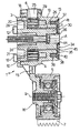
- For an improved understanding of the invention a preferred embodiment will now be described below, by way of non-exhaustive example and with reference to the accompanying drawing which shows an axial section thereof.
- With reference to the illustration, in its entirety 1 denotes a stretcher for a belt 2 with multiple grooves (multi-V) for driving the auxiliary elements (not shown) of an internal combustion engine (not shown).
- In known manner the stretcher 1 substantially comprises a fixed part 3 suitable for being rigidly connected to a support structure (not shown), such as a support plate for the auxiliary elements which is fixed to the engine block, a movable part 4 hinged to the fixed part 3 about a first axis A, a
pulley 5 carried in projecting manner by the movable part 4 and rotating with respect thereto about a second axis B distinct from the first axis A and parallel thereto, and aspring 6 interposed between the fixed part 3 and the movable part 4, which loads the movable part in the direction tending to keep thepulley 5 in engagement with the belt 2. - More particularly, the fixed part 3 integrally comprises a
flange 10 suitable for cooperating axially with the support structure and atubular pin 11 of axis A extending axially in projecting manner from theflange 10. Theflange 10 has a plurality offrontal teeth 12 suitable for engaging respective seats (not shown) of the support structure to anchor the fixed part 3 in the angular direction. - The movable part 4 integrally comprises a
hub 13 coaxial to thepin 11 and mounted in a rotating manner thereon, anarm 15 extending radially in a projecting manner from thehub 13, and atubular portion 16, of axis B, integrally connected to an end of thearm 15 and having the function of supporting thepulley 5. - The
hub 13 of the movable part 4 is substantially bell-shaped and comprises afirst portion 18 and asecond portion 19 which are axially adjacent and have a larger and smaller diameter respectively. - For a section of its own axial length, the
first portion 18 is disposed round theflange 10 and is supported radially thereon by means of abush 20 which, with the saidflange 10, defines a friction torque of pre-determined coefficient. For the remaining section of its own length thefirst portion 18 delimits with thepin 11 anannular chamber 21 housing thespring 6. The latter comprises a strip of steel spiral-wound round thepin 11 and having aninternal end 24 secured in known manner to thepin 11 and anexternal end 25 secured in known manner to theportion 18. - The
second portion 19 is supported radially by thepin 11 with the interposition of abush 26 which defines with the said pin 11 a friction torque of pre-determined coefficient. - The
bush 20 and thebush 26 have respective end, internal and external respectively, flatannular flanges 28, 29 which cooperate axially with opposite flanks of thespring 6 and are interposed between the latter and, respectively, theflange 10 and thesecond portion 19 of thehub 13. - Finally the stretcher 1 comprises a
damping element 30 interposed between thepin 11 and the movable part 4. - The
damping element 30 substantially comprises a metallic cuppedcore 34 having a substantially flatcircular base wall 35 rigidly fixed onto afree end 36 of reduced diameter of thepin 11 and a substantially cylindricallateral wall 37 extending in projecting manner from an external periphery of thebase wall 35. - The
damping element 30 also has acoating 38 of plastics material extending over the face of thebase wall 35 facing towards thehub 13 and over the entire surface of thelateral wall 37, so as to form therewith anannular friction crown 39 engaging anannular seat 40, of complementary form, produced on afront face 41 of theportion 19 of thehub 13. The material of thecoating 38 is selected so as to define with the hub 13 a friction torque of pre-determined coefficient to ensure, in use, adequate oscillation damping properties. The contact between theannular crown 39 and therelative seat 40 conveniently takes place either along the internal and external cylindrical surfaces, or along the annular front surface of thecrown 39. - The
core 34 is provided with anaxial hole 44, engaged in forced manner by theend 36 of thepin 11; theend 36 is thus pressed onto the internal edge of thebase wall 35 so as to ensure a "pack" mounting on thepin 11, i.e. substantially with no axial play, of the group comprising thebush 20, thespring 6, thebush 26 and thehub 13. - The
coating 38 is applied to thecore 34 by means of over-moulding; for this purpose thecore 34 is provided with a plurality ofholes 45 surrounding theaxial hole 44 and suitable for being engaged by the material of thecoating 38, during the moulding phase, to ensure the anchorage of the saidcoating 38 to thecore 34. - The operation of the stretcher 1 is per se known and will not therefore be described in detail.
- The arrangement of the
spring 6, with theinternal end 24 secured to thepin 11 and theexternal end 25 to theportion 18 of thehub 13 enables the diameter of thepin 11 to be increased without penalizing the overall size of the said hub. The tilting moment caused by the pull of the belt is efficiently balanced by thebushes - Furthermore, the
radial flanges 28, 29 of thebushes damping element 30 help both to damp the oscillations and to support the movable part 4 with respect to the fixed part 3, further reducing the effects of the tilting moment. - Finally, it will be clear that modifications and variants which do not depart from the protective scope of the invention may be introduced to the stretcher 1 described.
Claims (6)
- Stretcher (1) for a transmission belt (2) of the type comprising a fixed part (3) suitable for being rigidly connected to a support structure and provided with a pin (11) defining a first axis (A), a movable part (4) provided with a hub (13) mounted on the said pin (11) rotating about the said first axis (A) with the interposition of a first bush (26), a pulley (5) carried by the said movable part (4) and rotating with respect thereto about a second axis (B) distinct from the said first axis (A) and parallel thereto, and flexible means (6) interposed between the said fixed part (3) and the said movable part (4) and suitable for loading in use the said movable part (4) in the direction tending to keep the said pulley (5) in engagement with the relative said belt (2), the said flexible means comprising a spiral spring (6) wound round the said pin (11) the said stretcher (1) also comprising a second bush (20) interposed between an annular portion (18) of the said hub (13) and the said fixed part (3), the said bushes (20, 26) being disposed on parts axially opposite with respect to the said spring (6), characterized in that the spring has an internal end (24) secured to the said pin (11) and an external end (25) secured to the annular portion (18) of the said hub (13).
- Stretcher according to Claim 1, characterized in that the said bushes (26, 20) comprise respective radial flanges (29, 28) cooperating axially from opposite parts with the said spring (6).
- Stretcher according to Claim 1 or 2, characterized in that it comprises a damping element (30) provided with a securing portion (35) rigidly fixed to one (3) of the said fixed and movable parts (3, 4) and with an annular friction portion (39) extending axially from the said securing portion (35) and cooperating with a seat (40) produced in another (4) of the said fixed and movable parts (3, 4) and having a form complementary to the said annular friction portion (39).
- Stretcher according to Claim 3, characterized in that the said damping element (30) comprises a metallic core (34) and a coating (38) of plastics material extending at least over the said annular friction portion (39).
- Stretcher according to one of the preceding Claims, characterized in that the said securing portion is a substantially flat base wall (35) of the said damping element (30) fixed to the said pin (11) of the said fixed part (3) of the said stretcher (1), and that the said annular friction portion (39) is substantially cylindrical in shape and extends in a projecting manner from a periphery of the said base wall (35), the said seat being produced in the said movable part (4) of the said stretcher (1).
- Stretcher according to Claim 5, characterized in that the said base wall (35) of the said damping element (30) is fixed to an end portion (36) of the said pin (11), the said seat (40) for the said annular friction portion (39) of the said damping element (30) being produced on a front face (41) of the said hub (13).
Applications Claiming Priority (2)
| Application Number | Priority Date | Filing Date | Title |
|---|---|---|---|
| ITTO970074 | 1997-01-31 | ||
| IT97TO000074A IT1291487B1 (en) | 1997-01-31 | 1997-01-31 | TENSIONER FOR A DRIVE BELT |
Publications (2)
| Publication Number | Publication Date |
|---|---|
| EP0856685A1 EP0856685A1 (en) | 1998-08-05 |
| EP0856685B1 true EP0856685B1 (en) | 2001-07-18 |
Family
ID=11415294
Family Applications (1)
| Application Number | Title | Priority Date | Filing Date |
|---|---|---|---|
| EP98101545A Expired - Lifetime EP0856685B1 (en) | 1997-01-31 | 1998-01-29 | Tensioner for a transmission belt |
Country Status (8)
| Country | Link |
|---|---|
| US (1) | US5993343A (en) |
| EP (1) | EP0856685B1 (en) |
| JP (1) | JPH10252846A (en) |
| AR (1) | AR011599A1 (en) |
| BR (1) | BR9800412A (en) |
| DE (1) | DE69801123T2 (en) |
| ES (1) | ES2159899T3 (en) |
| IT (1) | IT1291487B1 (en) |
Families Citing this family (14)
| Publication number | Priority date | Publication date | Assignee | Title |
|---|---|---|---|---|
| DE29720776U1 (en) * | 1997-11-22 | 1998-01-15 | Skf Gmbh, 97421 Schweinfurt | Fastening device for belt rolls |
| JP3681032B2 (en) * | 1997-11-27 | 2005-08-10 | 光洋精工株式会社 | Auto tensioner |
| FR2794823B1 (en) * | 1999-06-14 | 2001-08-10 | Skf France | FIXING DEVICE FOR ROLLER ROLLER AND ROLLER ROLLER COMPRISING SUCH A DEVICE |
| US6231465B1 (en) * | 1999-08-13 | 2001-05-15 | Dayco Products, Inc. | Belt tensioner assembly with unidirectional damping |
| DE10112641A1 (en) * | 2001-03-16 | 2002-09-19 | Stihl Maschf Andreas | Rolling bearings, in particular for mounting a shaft of a gear head for a hand-held implement |
| ITTO20010584A1 (en) * | 2001-06-15 | 2002-12-15 | Dayco Europe Srl | TENSIONER FOR A DRIVE BELT. |
| DE10143386B4 (en) * | 2001-09-05 | 2004-05-06 | Zf Sachs Ag | Parking lock for a motor vehicle |
| WO2004104435A1 (en) * | 2003-05-20 | 2004-12-02 | The Gates Corporation | Load spreader |
| DE102004025739A1 (en) * | 2004-05-26 | 2005-12-15 | Ina-Schaeffler Kg | Tensioning device for looping medium of motor vehicle, has rotation-symmetric, cup-shaped pick-up unit with base provided at its smaller end face, in which base corresponds to end face of base unit, where units are fastened to vehicle part |
| JP4922667B2 (en) * | 2006-05-30 | 2012-04-25 | 日産自動車株式会社 | Tensioner |
| US9249866B2 (en) * | 2013-03-15 | 2016-02-02 | Dayco Ip Holdings, Llc | Belt tensioner for a power transmission belt system |
| WO2022182809A1 (en) * | 2021-02-26 | 2022-09-01 | Dayco Ip Holdings, Llc | High-offset belt tensioner with counterbalance torsion spring force |
| WO2024155771A1 (en) * | 2023-01-20 | 2024-07-25 | Dayco Ip Holdings, Llc | Belt tensioner with integrated idler pulley for an endless drive belt of an engine |
| WO2026139821A1 (en) * | 2024-12-24 | 2026-07-02 | Muviq S.r.l. | Tensioner for an accessory drive of a motor vehicle and accessory drive including such a tensioner |
Family Cites Families (11)
| Publication number | Priority date | Publication date | Assignee | Title |
|---|---|---|---|---|
| US2490974A (en) * | 1946-05-07 | 1949-12-13 | B L Mallory Company | Shock absorber |
| US4657137A (en) * | 1981-05-22 | 1987-04-14 | North American Philips Corporation | Multi-chip packaging system |
| US4596538A (en) * | 1984-08-23 | 1986-06-24 | Dayco Corporation | Belt tensioner |
| EP0362619B1 (en) * | 1988-09-22 | 1993-01-13 | Koyo Seiko Co., Ltd. | Belt tensioner |
| US4981461A (en) * | 1989-06-12 | 1991-01-01 | Dayco Products, Inc. | Belt tensioner, kit therefor and methods of making the same |
| US5030171A (en) * | 1989-07-07 | 1991-07-09 | Dayco Products, Inc. | Belt tensioner and method of making the same |
| US4938734A (en) * | 1989-09-06 | 1990-07-03 | Dayco Products, Inc. | Belt tensioner and method of making the same |
| US5035679A (en) * | 1990-04-24 | 1991-07-30 | Dayco Products, Inc. | Belt tensioner and method of making the same |
| US5131889A (en) * | 1990-10-22 | 1992-07-21 | Ford Motor Company | Automotive engine accessory drive tensioner |
| CA2074637C (en) * | 1991-07-31 | 1998-11-10 | Kazuki Kawashima | Belt tension adjusting device |
| DE19623485B4 (en) * | 1995-06-14 | 2006-08-24 | Gates Unitta Asia Co. | tensioner |
-
1997
- 1997-01-31 IT IT97TO000074A patent/IT1291487B1/en active IP Right Grant
-
1998
- 1998-01-26 US US09/012,689 patent/US5993343A/en not_active Expired - Lifetime
- 1998-01-29 EP EP98101545A patent/EP0856685B1/en not_active Expired - Lifetime
- 1998-01-29 ES ES98101545T patent/ES2159899T3/en not_active Expired - Lifetime
- 1998-01-29 DE DE69801123T patent/DE69801123T2/en not_active Expired - Lifetime
- 1998-01-30 AR ARP980100421A patent/AR011599A1/en unknown
- 1998-02-02 JP JP10020793A patent/JPH10252846A/en active Pending
- 1998-02-02 BR BR9800412A patent/BR9800412A/en not_active IP Right Cessation
Also Published As
| Publication number | Publication date |
|---|---|
| ITTO970074A1 (en) | 1998-07-31 |
| AR011599A1 (en) | 2000-08-30 |
| DE69801123T2 (en) | 2001-10-31 |
| IT1291487B1 (en) | 1999-01-11 |
| US5993343A (en) | 1999-11-30 |
| DE69801123D1 (en) | 2001-08-23 |
| JPH10252846A (en) | 1998-09-22 |
| EP0856685A1 (en) | 1998-08-05 |
| BR9800412A (en) | 1999-06-29 |
| ES2159899T3 (en) | 2001-10-16 |
Similar Documents
| Publication | Publication Date | Title |
|---|---|---|
| US5993340A (en) | Tightener for a transmission belt | |
| US5993343A (en) | Stretcher for a transmission belt | |
| US4698049A (en) | Belt tensioner with frustoconical pivot bearing | |
| US4983145A (en) | Apparatus for automatically tensioning a drive belt | |
| JP4535517B2 (en) | Serpentine belt drive system with improved overrun alternator decoupler | |
| EP0866240B1 (en) | Belt tensioner | |
| EP2140172B1 (en) | Wear compensated tensioner | |
| JP3792160B2 (en) | Tensioner | |
| US4988071A (en) | Mounting mechanism for an automotive air conditioning compressor | |
| KR100403522B1 (en) | Tension mechanism for traction means with conical sliding bearing | |
| US7004865B2 (en) | Tensioning means for traction mechanisms, especially belt tensioning means | |
| KR950002995B1 (en) | Belt tensioner with increased range of motion | |
| JPS622182B2 (en) | ||
| US12601381B2 (en) | Decoupler with torque-limiting feature to protect components thereof | |
| US6050382A (en) | Clutch disk for a motor vehicle friction clutch | |
| JPH0396746A (en) | Tension device for driving belt | |
| EP0364277B1 (en) | Compact automatic belt tensioner | |
| JPH109285A (en) | Friction clutch with wear compensation device | |
| HK1046949B (en) | Tensioner comprising a damping mechanism | |
| EP1267096B1 (en) | Drive belt tensioner | |
| EP4248103B1 (en) | Decoupler for endless drive arrangement | |
| GB2329228A (en) | Tensioning device for drive belts | |
| JP4088496B2 (en) | Auto tensioner | |
| JP2000230612A (en) | Belt transmission | |
| JPH07113447A (en) | Auto tensioner |
Legal Events
| Date | Code | Title | Description |
|---|---|---|---|
| PUAI | Public reference made under article 153(3) epc to a published international application that has entered the european phase |
Free format text: ORIGINAL CODE: 0009012 |
|
| AK | Designated contracting states |
Kind code of ref document: A1 Designated state(s): DE ES FR GB IT SE |
|
| AX | Request for extension of the european patent |
Free format text: AL;LT;LV;MK;RO;SI |
|
| 17P | Request for examination filed |
Effective date: 19990130 |
|
| AKX | Designation fees paid |
Free format text: AT BE CH DE DK ES FI FR GB GR IE IT LI LU MC NL PT SE |
|
| AXX | Extension fees paid |
Free format text: AL;LT;LV;MK;RO;SI |
|
| RBV | Designated contracting states (corrected) |
Designated state(s): DE ES FR GB IT SE |
|
| RAP1 | Party data changed (applicant data changed or rights of an application transferred) |
Owner name: DAYCO EUROPE S.R.L. |
|
| GRAG | Despatch of communication of intention to grant |
Free format text: ORIGINAL CODE: EPIDOS AGRA |
|
| RIC1 | Information provided on ipc code assigned before grant |
Free format text: 7F 16H 7/12 A, 7F 16F 7/06 B, 7F 16F 7/02 B |
|
| RTI1 | Title (correction) |
Free format text: TENSIONER FOR A TRANSMISSION BELT |
|
| 17Q | First examination report despatched |
Effective date: 20001117 |
|
| GRAG | Despatch of communication of intention to grant |
Free format text: ORIGINAL CODE: EPIDOS AGRA |
|
| GRAH | Despatch of communication of intention to grant a patent |
Free format text: ORIGINAL CODE: EPIDOS IGRA |
|
| GRAH | Despatch of communication of intention to grant a patent |
Free format text: ORIGINAL CODE: EPIDOS IGRA |
|
| GRAA | (expected) grant |
Free format text: ORIGINAL CODE: 0009210 |
|
| AK | Designated contracting states |
Kind code of ref document: B1 Designated state(s): DE ES FR GB IT SE |
|
| REF | Corresponds to: |
Ref document number: 69801123 Country of ref document: DE Date of ref document: 20010823 |
|
| ITF | It: translation for a ep patent filed | ||
| REG | Reference to a national code |
Ref country code: ES Ref legal event code: FG2A Ref document number: 2159899 Country of ref document: ES Kind code of ref document: T3 |
|
| ET | Fr: translation filed | ||
| REG | Reference to a national code |
Ref country code: GB Ref legal event code: IF02 |
|
| PLBE | No opposition filed within time limit |
Free format text: ORIGINAL CODE: 0009261 |
|
| STAA | Information on the status of an ep patent application or granted ep patent |
Free format text: STATUS: NO OPPOSITION FILED WITHIN TIME LIMIT |
|
| 26N | No opposition filed | ||
| PGFP | Annual fee paid to national office [announced via postgrant information from national office to epo] |
Ref country code: SE Payment date: 20030128 Year of fee payment: 6 |
|
| PG25 | Lapsed in a contracting state [announced via postgrant information from national office to epo] |
Ref country code: SE Free format text: LAPSE BECAUSE OF NON-PAYMENT OF DUE FEES Effective date: 20040130 |
|
| EUG | Se: european patent has lapsed | ||
| PGFP | Annual fee paid to national office [announced via postgrant information from national office to epo] |
Ref country code: FR Payment date: 20120217 Year of fee payment: 15 |
|
| PGFP | Annual fee paid to national office [announced via postgrant information from national office to epo] |
Ref country code: DE Payment date: 20120308 Year of fee payment: 15 |
|
| PGFP | Annual fee paid to national office [announced via postgrant information from national office to epo] |
Ref country code: GB Payment date: 20120201 Year of fee payment: 15 |
|
| PGFP | Annual fee paid to national office [announced via postgrant information from national office to epo] |
Ref country code: ES Payment date: 20120127 Year of fee payment: 15 |
|
| GBPC | Gb: european patent ceased through non-payment of renewal fee |
Effective date: 20130129 |
|
| REG | Reference to a national code |
Ref country code: FR Ref legal event code: ST Effective date: 20130930 |
|
| PG25 | Lapsed in a contracting state [announced via postgrant information from national office to epo] |
Ref country code: DE Free format text: LAPSE BECAUSE OF NON-PAYMENT OF DUE FEES Effective date: 20130801 |
|
| REG | Reference to a national code |
Ref country code: DE Ref legal event code: R119 Ref document number: 69801123 Country of ref document: DE Effective date: 20130801 |
|
| PG25 | Lapsed in a contracting state [announced via postgrant information from national office to epo] |
Ref country code: GB Free format text: LAPSE BECAUSE OF NON-PAYMENT OF DUE FEES Effective date: 20130129 Ref country code: FR Free format text: LAPSE BECAUSE OF NON-PAYMENT OF DUE FEES Effective date: 20130131 |
|
| REG | Reference to a national code |
Ref country code: ES Ref legal event code: FD2A Effective date: 20140324 |
|
| PG25 | Lapsed in a contracting state [announced via postgrant information from national office to epo] |
Ref country code: ES Free format text: LAPSE BECAUSE OF NON-PAYMENT OF DUE FEES Effective date: 20130130 |
|
| PGFP | Annual fee paid to national office [announced via postgrant information from national office to epo] |
Ref country code: IT Payment date: 20170103 Year of fee payment: 20 |