EP0856597A1 - Process for monitoring the electrolyte circulation in an electrolysis cell - Google Patents
Process for monitoring the electrolyte circulation in an electrolysis cell Download PDFInfo
- Publication number
- EP0856597A1 EP0856597A1 EP98100776A EP98100776A EP0856597A1 EP 0856597 A1 EP0856597 A1 EP 0856597A1 EP 98100776 A EP98100776 A EP 98100776A EP 98100776 A EP98100776 A EP 98100776A EP 0856597 A1 EP0856597 A1 EP 0856597A1
- Authority
- EP
- European Patent Office
- Prior art keywords
- electrolysis
- current
- cell
- gradient
- electrolyte
- Prior art date
- Legal status (The legal status is an assumption and is not a legal conclusion. Google has not performed a legal analysis and makes no representation as to the accuracy of the status listed.)
- Granted
Links
- 238000005868 electrolysis reaction Methods 0.000 title claims abstract description 89
- 238000000034 method Methods 0.000 title claims abstract description 32
- 230000008569 process Effects 0.000 title claims abstract description 29
- 239000003792 electrolyte Substances 0.000 title claims abstract description 27
- 238000012544 monitoring process Methods 0.000 title claims abstract description 8
- 230000015572 biosynthetic process Effects 0.000 claims abstract description 10
- 238000005259 measurement Methods 0.000 claims abstract description 5
- 230000000007 visual effect Effects 0.000 claims abstract 2
- 229910052709 silver Inorganic materials 0.000 claims description 15
- 239000004332 silver Substances 0.000 claims description 15
- 238000011084 recovery Methods 0.000 claims description 14
- BQCADISMDOOEFD-UHFFFAOYSA-N Silver Chemical compound [Ag] BQCADISMDOOEFD-UHFFFAOYSA-N 0.000 claims description 13
- 229910052751 metal Inorganic materials 0.000 description 8
- 239000002184 metal Substances 0.000 description 8
- 150000002500 ions Chemical class 0.000 description 7
- 239000000243 solution Substances 0.000 description 6
- 230000007423 decrease Effects 0.000 description 5
- 230000008901 benefit Effects 0.000 description 4
- 238000009792 diffusion process Methods 0.000 description 4
- 230000000694 effects Effects 0.000 description 4
- 238000011156 evaluation Methods 0.000 description 4
- 238000005755 formation reaction Methods 0.000 description 4
- 239000003990 capacitor Substances 0.000 description 3
- 230000008859 change Effects 0.000 description 3
- 239000007788 liquid Substances 0.000 description 3
- 229910021645 metal ion Inorganic materials 0.000 description 3
- -1 silver ions Chemical class 0.000 description 3
- 239000000126 substance Substances 0.000 description 3
- 238000013461 design Methods 0.000 description 2
- 238000001514 detection method Methods 0.000 description 2
- 230000003647 oxidation Effects 0.000 description 2
- 238000007254 oxidation reaction Methods 0.000 description 2
- 238000012360 testing method Methods 0.000 description 2
- 230000032258 transport Effects 0.000 description 2
- NINIDFKCEFEMDL-UHFFFAOYSA-N Sulfur Chemical compound [S] NINIDFKCEFEMDL-UHFFFAOYSA-N 0.000 description 1
- LSNNMFCWUKXFEE-UHFFFAOYSA-N Sulfurous acid Chemical compound OS(O)=O LSNNMFCWUKXFEE-UHFFFAOYSA-N 0.000 description 1
- 229910052946 acanthite Inorganic materials 0.000 description 1
- 230000032683 aging Effects 0.000 description 1
- 239000007864 aqueous solution Substances 0.000 description 1
- 230000002925 chemical effect Effects 0.000 description 1
- 238000006243 chemical reaction Methods 0.000 description 1
- 230000001419 dependent effect Effects 0.000 description 1
- 230000005684 electric field Effects 0.000 description 1
- 238000002848 electrochemical method Methods 0.000 description 1
- 230000001939 inductive effect Effects 0.000 description 1
- 238000009434 installation Methods 0.000 description 1
- 230000003993 interaction Effects 0.000 description 1
- 230000037427 ion transport Effects 0.000 description 1
- 239000000463 material Substances 0.000 description 1
- 238000001465 metallisation Methods 0.000 description 1
- 230000005012 migration Effects 0.000 description 1
- 238000013508 migration Methods 0.000 description 1
- 239000000203 mixture Substances 0.000 description 1
- 239000010956 nickel silver Substances 0.000 description 1
- 238000001556 precipitation Methods 0.000 description 1
- 230000009467 reduction Effects 0.000 description 1
- 238000011946 reduction process Methods 0.000 description 1
- XUARKZBEFFVFRG-UHFFFAOYSA-N silver sulfide Chemical compound [S-2].[Ag+].[Ag+] XUARKZBEFFVFRG-UHFFFAOYSA-N 0.000 description 1
- 229940056910 silver sulfide Drugs 0.000 description 1
- 239000007787 solid Substances 0.000 description 1
- 239000002904 solvent Substances 0.000 description 1
- 229910052717 sulfur Inorganic materials 0.000 description 1
- 239000011593 sulfur Substances 0.000 description 1
- 238000012546 transfer Methods 0.000 description 1
- 230000007704 transition Effects 0.000 description 1
- 230000001960 triggered effect Effects 0.000 description 1
Images

Classifications
-
- C—CHEMISTRY; METALLURGY
- C02—TREATMENT OF WATER, WASTE WATER, SEWAGE, OR SLUDGE
- C02F—TREATMENT OF WATER, WASTE WATER, SEWAGE, OR SLUDGE
- C02F1/00—Treatment of water, waste water, or sewage
- C02F1/46—Treatment of water, waste water, or sewage by electrochemical methods
- C02F1/461—Treatment of water, waste water, or sewage by electrochemical methods by electrolysis
- C02F1/46104—Devices therefor; Their operating or servicing
-
- C—CHEMISTRY; METALLURGY
- C25—ELECTROLYTIC OR ELECTROPHORETIC PROCESSES; APPARATUS THEREFOR
- C25B—ELECTROLYTIC OR ELECTROPHORETIC PROCESSES FOR THE PRODUCTION OF COMPOUNDS OR NON-METALS; APPARATUS THEREFOR
- C25B15/00—Operating or servicing cells
-
- C—CHEMISTRY; METALLURGY
- C25—ELECTROLYTIC OR ELECTROPHORETIC PROCESSES; APPARATUS THEREFOR
- C25C—PROCESSES FOR THE ELECTROLYTIC PRODUCTION, RECOVERY OR REFINING OF METALS; APPARATUS THEREFOR
- C25C1/00—Electrolytic production, recovery or refining of metals by electrolysis of solutions
- C25C1/20—Electrolytic production, recovery or refining of metals by electrolysis of solutions of noble metals
-
- C—CHEMISTRY; METALLURGY
- C25—ELECTROLYTIC OR ELECTROPHORETIC PROCESSES; APPARATUS THEREFOR
- C25C—PROCESSES FOR THE ELECTROLYTIC PRODUCTION, RECOVERY OR REFINING OF METALS; APPARATUS THEREFOR
- C25C7/00—Constructional parts, or assemblies thereof, of cells; Servicing or operating of cells
- C25C7/06—Operating or servicing
-
- C—CHEMISTRY; METALLURGY
- C02—TREATMENT OF WATER, WASTE WATER, SEWAGE, OR SLUDGE
- C02F—TREATMENT OF WATER, WASTE WATER, SEWAGE, OR SLUDGE
- C02F1/00—Treatment of water, waste water, or sewage
- C02F1/46—Treatment of water, waste water, or sewage by electrochemical methods
- C02F1/461—Treatment of water, waste water, or sewage by electrochemical methods by electrolysis
- C02F1/467—Treatment of water, waste water, or sewage by electrochemical methods by electrolysis by electrochemical disinfection; by electrooxydation or by electroreduction
- C02F1/4676—Treatment of water, waste water, or sewage by electrochemical methods by electrolysis by electrochemical disinfection; by electrooxydation or by electroreduction by electroreduction
- C02F1/4678—Treatment of water, waste water, or sewage by electrochemical methods by electrolysis by electrochemical disinfection; by electrooxydation or by electroreduction by electroreduction of metals
-
- C—CHEMISTRY; METALLURGY
- C02—TREATMENT OF WATER, WASTE WATER, SEWAGE, OR SLUDGE
- C02F—TREATMENT OF WATER, WASTE WATER, SEWAGE, OR SLUDGE
- C02F2103/00—Nature of the water, waste water, sewage or sludge to be treated
- C02F2103/34—Nature of the water, waste water, sewage or sludge to be treated from industrial activities not provided for in groups C02F2103/12 - C02F2103/32
- C02F2103/40—Nature of the water, waste water, sewage or sludge to be treated from industrial activities not provided for in groups C02F2103/12 - C02F2103/32 from the manufacture or use of photosensitive materials
-
- C—CHEMISTRY; METALLURGY
- C02—TREATMENT OF WATER, WASTE WATER, SEWAGE, OR SLUDGE
- C02F—TREATMENT OF WATER, WASTE WATER, SEWAGE, OR SLUDGE
- C02F2201/00—Apparatus for treatment of water, waste water or sewage
- C02F2201/46—Apparatus for electrochemical processes
- C02F2201/461—Electrolysis apparatus
- C02F2201/46105—Details relating to the electrolytic devices
- C02F2201/4612—Controlling or monitoring
- C02F2201/46125—Electrical variables
-
- C—CHEMISTRY; METALLURGY
- C02—TREATMENT OF WATER, WASTE WATER, SEWAGE, OR SLUDGE
- C02F—TREATMENT OF WATER, WASTE WATER, SEWAGE, OR SLUDGE
- C02F2201/00—Apparatus for treatment of water, waste water or sewage
- C02F2201/46—Apparatus for electrochemical processes
- C02F2201/461—Electrolysis apparatus
- C02F2201/46105—Details relating to the electrolytic devices
- C02F2201/4612—Controlling or monitoring
- C02F2201/46145—Fluid flow
-
- C—CHEMISTRY; METALLURGY
- C02—TREATMENT OF WATER, WASTE WATER, SEWAGE, OR SLUDGE
- C02F—TREATMENT OF WATER, WASTE WATER, SEWAGE, OR SLUDGE
- C02F2201/00—Apparatus for treatment of water, waste water or sewage
- C02F2201/46—Apparatus for electrochemical processes
- C02F2201/461—Electrolysis apparatus
- C02F2201/46105—Details relating to the electrolytic devices
- C02F2201/4612—Controlling or monitoring
- C02F2201/4615—Time
Definitions
- the invention relates to a process for monitoring the electrolyte circulation in an electrolysis cell, in particular for silver recovery from photographic solutions, in which an electrolyte flow generated by a circulation pump is generated between the electrodes of the electrolysis cell and the electrolysis is performed by a constant electrolysis current or electrode potential.
- phase boundary layer When an electrode is dipped into an electrolyte, a so-called phase boundary layer usually forms. It is known in theory that first an inner boundary layer, the so-called inner Helmholtz surface, is formed, which is nearest to the electrode. It is formed mainly from the molecules of the solvent. Solvated ions can only penetrate through to this first boundary layer. They themselves thereby form a second layer, the so-called outer Helmholtz surface. The interaction between the charged metal of the electrode and the solvated ions takes place only via long-ranged electro-static forces. A layer is therefore formed away from the electrode and into the solution, which is called the diffusion layer. The thickness of this layer depends on the ion concentration of the solution. This electrode/liquid boundary layer can be aptly described as a capacitor.
- the metal ions are now taken away from the vicinity of the cathode and deposited as metal atoms when the appropriate charge is received. This results in a depletion of these metal ion species near the cathode.
- the processes a) and b) are substantially responsible for ion transport. Both processes generally transport the ions in a substantially less effective way than convection.
- a boundary layer of increasing thickness is formed in which the concentration of the ions to be deposited decreases and leads to an increase in the potential with a constant current. If the potential is kept constant, the electrolysis current drops, and hence by a considerable extent the metal recovery rate too. If however the current is injected from the outside as a constant current, then other ions assume the charge transport, and unwelcome oxidation and reduction processes occur at the electrodes. Furthermore, the efficiency of the metal recovery process drops even further.
- the recovery of silver from photographic fixing bath solution is taken as an example here.
- the silver ions are deposited on the cathode as solid silver metal while absorbing an electron.
- new silver ions are brought to the cathode. If convection fails, i.e. no liquid flow at the cathode surface, this leads to a depletion of silver ions at the cathode surface.
- the outer potential is kept constant, the current drops and the recovery rate is considerably reduced. If the current is kept constant, then the potential increases and unwelcome chemical reactions result, such as the formation of silver sulfide, the oxidation of sulfite at the anode or sulfur precipitation.
- the fixing bath becomes unusable, which is not tolerable for silver recovery with circulation system.
- the circulation of the electrolyte at the electrode surface therefore results in a reduction of the diffusion layer.
- the better the circulation the better the metal deposition on the cathode.
- the fundamental electrochemical effects are described in, for example: "Electrochemical Methods", A.J. Bard, L.R. Faulkner, John Wiley & Sons, New York, 1980.
- an interface for a silver recovery unit for detecting the operating state of at least one pump is known from DE 195 09 757 A1.
- a sensor for detection of the operating state of the pump is installed outside the pump such that during the installation any interference with the electronic control unit of the pump or with the pump itself is avoidable.
- the output signal of the sensor is passed to a downstream electronic circuit comprising a series connection of an amplifier means, a first filter means, a rectifier means, a second filter means and a comparator.
- the object underlying the present invention is to monitor the circulation of an electrolyte in an electrolysis cell dependably and inexpensively in a way that leads to an error already being indicated while there is still circulation inside the cell, which however does not meet the above requirements for whatever reason.
- the process has, with the use of a constant electrolysis current, the advantage that it is generally independent of the current voltage value being set by the electrolysis cell. This means that it does not matter which cell voltage is set. It has become evident that when a new cathode is used or when the fixing bath is changed while a constant current is in use, the voltages are generally different. Voltage losses also play no part in the supply lines to the electrodes. With a fixed electrolysis current, therefore, the absolute voltage cannot be used for determining the electrolyte circulation, since the latter depends on the aforementioned effects; instead it is advantageous only to evaluate the voltage change.
- the process also has the advantage, when a constant electrode potential is used accordingly, that then only the current change being set has to be evaluated analogously to the above voltage change.
- a further advantage obtained is that no moving parts are required for implementation of the process. There are also no wear parts, no aging phenomena and no chemical effects on components that might affect the process. Recalibration or checking of the measuring equipment used is also not necessary.
- the process is therefore substantially independent of the respective states of the electrolyte and of the electrodes.
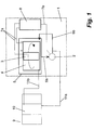
- Fig. 1 shows in diagrammatic form an electrolysis unit 1 in which circulation of fixing bath solution is continuously maintained between a fixing bath tank 10 of a developing machine 9 and the electrolysis unit 1.
- a circulation pump 2 of the electrolysis unit 1 part of the pumped electrolyte can be pumped back to the fixing bath tank 10 via a supply pipe 11a.
- the same flow rate is supplied via the overflow of the tank 10 by means of a return pipe 11b to an electrolysis cell 5.
- the silver is transferred in the fixing bath tank 10 from the photographic material to the solution, circulated into the electrolysis unit 1 and there deposited on the cathode 4 of the electrolysis cell 5.
- a control unit 8 monitors the recovery process, e.g. by measurement of the cell voltage across anode 3 and cathode 4.
- the circulation pump 2 in the electrolysis unit 1 ensures the necessary circulation in the electrolysis cell 5, e.g. via the two hose lines 6a and 6b.
- the cathode 4 and anode 3 shown diagrammatically in Fig. 1 are cylindrical in shape.
- the active surface of the cathode is the inner surface of the cylinder, i.e. silver is deposited onto it. It should however be pointed out that the type of design of cathode and anode is not important, nor is the type of connection between the electrolysis unit and the developing machine, since the process is independent of them.
- the electrodes do not have to be cylinder-symmetrical, and instead can have any other form. What is important is that flow takes place at the electrode surfaces.
- the control unit 8 comprises a current supply unit and can be designed with microprocessor or analog control.
- the current supply of the unit 8 delivers a DC current via the lines 7a to anode 3 and cathode 4, the polarities of which are (+) and (-) respectively.
- the cell voltage necessary for measurement between anode and cathode can be tapped directly in the control unit 8.
- the pump 2 is likewise supplied by the control unit 8 via the electrical line 7b and can also be switched on and off from there.
- Periods 2 and 3 are shown as examples in Fig. 2. They show typical curves with a current of 3 A when the pump is switched on and off at intervals of, for example, about 4 minutes. The switching times are identified by "E” (for ON) and "A” (for OFF). It can be seen clearly that the effect is much more pronounced with 3 A than with 1 A.
- an error signal (E2) is generated and electrolysis is interrupted or aborted, as already explained in the case of evaluation in respect of presence of an electrolyte flow sufficient for electrolysis.
- the process can also be applied when the electrode potential is kept constant, such that the electrolysis current adjusts to suit the overall resistance of the system.
- the three electrolysis state changes to be effected in the cell 5 would for example be performable as follows:
- sequence of the described state changes of the electrolyte in the electrolysis cell does not have to be precisely in this way.
- the process is also usable when a sequence as follows is selected:
- the frequency for checking the circulation of the electrolyte depends on the respective application (chemical property of the electrode surfaces, chemical composition of the electrolyte) and must be set accordingly.
- a first test e.g. 2 hours after switch-on of the electrolysis unit, and further tests every 12 hours after that are sufficient.
- the occurrence of the checks can preferably also be made dependent on the amount of silver recovered, e.g. after every 20 grams.
- the recovered metal mass can, for example, be calculated automatically by the control unit 8 from the parameters such as electrolysis time, current and efficiency.
Landscapes
- Chemical & Material Sciences (AREA)
- Engineering & Computer Science (AREA)
- Chemical Kinetics & Catalysis (AREA)
- Electrochemistry (AREA)
- Organic Chemistry (AREA)
- Materials Engineering (AREA)
- Metallurgy (AREA)
- Life Sciences & Earth Sciences (AREA)
- General Chemical & Material Sciences (AREA)
- Hydrology & Water Resources (AREA)
- Environmental & Geological Engineering (AREA)
- Water Supply & Treatment (AREA)
- Electrolytic Production Of Metals (AREA)
- Water Treatment By Electricity Or Magnetism (AREA)
- Electrolytic Production Of Non-Metals, Compounds, Apparatuses Therefor (AREA)
- Silver Salt Photography Or Processing Solution Therefor (AREA)
- Photographic Developing Apparatuses (AREA)
Abstract
- Setting of at least three different electrolysis states in the cell by switching on and off of the circulation pump and said electrolysis current or the voltage at predetermined times,
- Multiple measurement of at least one electrolysis parameter in a predetermined period of time and formation of a mean value of the measured electrolyte parameter for each of the three electrolysis states,
- Formation of a first gradient ST1 from the mean values of the electrolysis parameters of the first and second electrolysis states and formation of a second gradient ST2 from the mean values of the electrolysis parameters of the second and third electrolysis states, and
- Comparison of the gradient ST1 with the absolute value of the gradient ST2, where a greatly reduced electrolyte circulation applies with ST1 < |ST2|, which is indicated as an error signal by a visual or acoustic signal element.
Description
- flow monitors, which for example trigger an alarm when the flow in the supply or discharge lines to the electrolysis cell is interrupted;
- flow meters, for defining a minimum throughput rate below which an alarm is triggered;
- thermal flow monitors, or
- inductive flow meters, for obtaining a precise and dependable measurement of the throughput.
- Fig. 1
- an example for the use of the process in a connection of an electrolysis unit to a film developing machine, and
- Fig. 2
- the electrolysis voltage curve over time for two different constant electrolysis currents.
- M2:
- cell voltage mean value from
period 2 - M1:
- cell voltage mean value from
period 1 - mV:
- millivolt
- 1st period:
- circulation pump on, electrolysis current on
- 2nd period:
- circulation pump off, electrolysis current on
- 3rd period:
- circulation pump on,
Claims (9)
- Process for monitoring the electrolyte circulation in an electrolysis cell, in particular for silver recovery from photographic solutions, in which an electrolyte flow is generated by a circulation pump between the electrodes of said electrolysis cell and the electrolysis is performed by a constant electrolysis current or electrode potential, characterized by the following process steps:Setting of at least three different electrolysis states in the cell by switching on and off of said circulation pump and said electrolysis current or the voltage at predetermined times,Multiple measurement of at least one electrolysis parameter in a predetermined period of time, and formation of a mean value of the measured electrolyte parameter for each of said three electrolysis states,Formation of a first gradient ST1 from the mean values of said electrolysis parameters of said first and second electrolysis states and formation of a second gradient ST2 from the mean values of said electrolysis parameters of said second and third electrolysis states, andComparison of said gradient ST1 with the absolute value of said gradient ST2, where a greatly reduced electrolyte circulation applies with ST1 < |ST2|, which is indicated as an error signal by a visual or acoustic signal element.
- Process according to Claim 1, characterized in that the at least one electrolysis parameter to be measured with constant electrolysis current is the voltage to be set between said electrodes.
- Process according to Claim 1, characterized in that the at least one electrolysis parameter to be measured with constant electrode potential is the current flowing between said electrodes.
- Process according to Claim 1, characterized in that the electrolysis process is interrupted when said error signal is generated by switch-off of said circulating pump and of either said constant electrolysis current used or said constant electrode potential.
- Process according to Claim 1 and Claim 2, characterized in that the electrolysis process is switched off upon meeting the criterion
- Process according to Claim 1 and Claim 2, characterized in that said first electrolysis state of said cell is achieved with said circulation pump and said electrolysis current switched off, said second electrolysis state with said circulation pump switched off and said electrolysis current switched on, and said third electrolysis state with said circulation pump and said electrolysis current switched on.
- Process according to Claim 6, characterized in that the on/off switching sequence of circulation pump and electrolysis current is interchangeable.
- Process according to Claim 1 and Claim 6, characterized in that each of the at least three different electrolysis states is maintained for a period of between 30 and 180 seconds.
- Process according to Claim 2, characterized in that said electrolysis current is between 1 and 3 A.
Applications Claiming Priority (2)
| Application Number | Priority Date | Filing Date | Title |
|---|---|---|---|
| DE19703900 | 1997-02-03 | ||
| DE19703900A DE19703900A1 (en) | 1997-02-03 | 1997-02-03 | Method for monitoring the electrolyte circulation in an electrolytic cell |
Publications (2)
| Publication Number | Publication Date |
|---|---|
| EP0856597A1 true EP0856597A1 (en) | 1998-08-05 |
| EP0856597B1 EP0856597B1 (en) | 2001-11-21 |
Family
ID=7819104
Family Applications (1)
| Application Number | Title | Priority Date | Filing Date |
|---|---|---|---|
| EP98100776A Expired - Lifetime EP0856597B1 (en) | 1997-02-03 | 1998-01-17 | Process for monitoring the electrolyte circulation in an electrolysis cell |
Country Status (4)
| Country | Link |
|---|---|
| US (1) | US5951842A (en) |
| EP (1) | EP0856597B1 (en) |
| JP (1) | JPH10259491A (en) |
| DE (2) | DE19703900A1 (en) |
Cited By (1)
| Publication number | Priority date | Publication date | Assignee | Title |
|---|---|---|---|---|
| EP1154044A1 (en) * | 2000-05-12 | 2001-11-14 | Eastman Kodak Company | Recovery of metal from solution |
Families Citing this family (7)
| Publication number | Priority date | Publication date | Assignee | Title |
|---|---|---|---|---|
| GB9815168D0 (en) * | 1998-07-13 | 1998-09-09 | Eastman Kodak Co | Recovery of metal from solution |
| GB9815167D0 (en) * | 1998-07-13 | 1998-09-09 | Eastman Kodak Co | Recovery of metal from solution |
| US6146518A (en) * | 1999-09-01 | 2000-11-14 | Stuart Energy Systems Inc. | Pressure differential control in an electrolytic cell |
| AU2001275997A1 (en) * | 2000-07-20 | 2002-02-05 | Proton Energy Systems, Inc. | Electrochemical cell system output control method and apparatus |
| DE10352708A1 (en) * | 2003-11-07 | 2005-06-09 | Würth Elektronik Pforzheim GmbH & Co. KG | Galvanizing device comprises a process bath container, electrodes arranged in the container, a unit for continuously filtering the bath, and a circulating unit for producing circulating currents between the electrodes |
| CA2548767A1 (en) * | 2003-12-03 | 2005-06-23 | Proton Energy Systems, Inc. | System for generating hydrogen and method thereof |
| CN114460227B (en) * | 2022-01-12 | 2023-10-31 | 杭州三耐环保科技股份有限公司 | Electrolyte abnormality monitoring method and system |
Family Cites Families (7)
| Publication number | Priority date | Publication date | Assignee | Title |
|---|---|---|---|---|
| US4675085A (en) * | 1985-07-31 | 1987-06-23 | Adalberto Vasquez | Method and apparatus for recovery of metal from solution |
| US5282934A (en) * | 1992-02-14 | 1994-02-01 | Academy Corporation | Metal recovery by batch electroplating with directed circulation |
| US5254226A (en) * | 1992-05-05 | 1993-10-19 | Ad Rem Manufacturing, Inc. | Electrolytic cell assembly and process for production of bromine |
| JP2623204B2 (en) * | 1993-02-26 | 1997-06-25 | 英雄 早川 | Water reforming method |
| DE4315433A1 (en) * | 1993-05-08 | 1994-11-10 | Kodak Ag | Method and device for controlling electrolytic silver recovery for two film processing machines |
| JPH08155460A (en) * | 1994-12-07 | 1996-06-18 | Tatsuo Okazaki | Electrolytic silver eluting device |
| WO1998001604A1 (en) * | 1996-07-10 | 1998-01-15 | Metafix Inc. | Electrolytic metal recovery method |
-
1997
- 1997-02-03 DE DE19703900A patent/DE19703900A1/en not_active Withdrawn
-
1998
- 1998-01-17 EP EP98100776A patent/EP0856597B1/en not_active Expired - Lifetime
- 1998-01-17 DE DE69802572T patent/DE69802572T2/en not_active Expired - Fee Related
- 1998-01-22 US US09/010,670 patent/US5951842A/en not_active Expired - Fee Related
- 1998-02-02 JP JP10021307A patent/JPH10259491A/en active Pending
Non-Patent Citations (1)
| Title |
|---|
| No relevant documents disclosed * |
Cited By (2)
| Publication number | Priority date | Publication date | Assignee | Title |
|---|---|---|---|---|
| EP1154044A1 (en) * | 2000-05-12 | 2001-11-14 | Eastman Kodak Company | Recovery of metal from solution |
| US6508928B2 (en) | 2000-05-12 | 2003-01-21 | Eastman Kodak Company | Recovery of metal from solution |
Also Published As
| Publication number | Publication date |
|---|---|
| JPH10259491A (en) | 1998-09-29 |
| EP0856597B1 (en) | 2001-11-21 |
| DE19703900A1 (en) | 1998-08-06 |
| DE69802572T2 (en) | 2002-11-07 |
| US5951842A (en) | 1999-09-14 |
| DE69802572D1 (en) | 2002-01-03 |
Similar Documents
| Publication | Publication Date | Title |
|---|---|---|
| US5180968A (en) | Method and apparatus for compensation of double layer charging current in electrochemical cells | |
| EP0856597B1 (en) | Process for monitoring the electrolyte circulation in an electrolysis cell | |
| JP2016524789A (en) | Estimating the charge state of the positive electrolyte solution in a working redox flow battery cell without a reference electrode | |
| US6207037B1 (en) | Recovery of metal from solution | |
| US7427346B2 (en) | Electrochemical drive circuitry and method | |
| EA001993B1 (en) | Method and arrangement for the electrochemical machining of a workpiece | |
| US20180074100A1 (en) | Electrical assembly and measurement circuit and method for monitoring a component thereof | |
| US20060151327A1 (en) | Analysis method | |
| CN119497821A (en) | Impurity detection auxiliary device, impurity detection auxiliary method and inspection liquid processing system | |
| US4263108A (en) | Control system for the electrolytic recovery of silver from photographic fixing solution | |
| US4537664A (en) | Method for continuously monitoring oxide thickness on moving aluminum foil | |
| JP4635249B2 (en) | Winding test equipment | |
| JP6732261B2 (en) | Plating equipment | |
| US6508928B2 (en) | Recovery of metal from solution | |
| CN115656262A (en) | Device welding state detection method, device, equipment and storage medium | |
| FI104189B (en) | Method and apparatus for on-line quality control of purified metal sulphate solution | |
| US20250003921A1 (en) | Method for operating an electrochemical measuring point and electrochemical measuring point | |
| SU1044964A1 (en) | Electroconductive object surface area determination method | |
| SU277089A1 (en) | METHOD FOR INSPECTION OF INSULATION OF CONCLUSIONS OF RESISTIVE ELECTRODE | |
| JPH11120910A (en) | Cleaning device and cleaning method | |
| DE4310203C1 (en) | Automatic capacitor polarity identification device - compares obtained integrals for application of positive and negative measuring voltages to capacitor electrode | |
| JPH05149989A (en) | Testing method for printed wiring board | |
| SU1173290A1 (en) | Method of electrochemical analysis and apparatus for accomplishment of same | |
| KR20200118864A (en) | Plating device and plating system | |
| CN109073444A (en) | For detecting the method for the water in diesel fuel filter and for the water sensor of application the method |
Legal Events
| Date | Code | Title | Description |
|---|---|---|---|
| PUAI | Public reference made under article 153(3) epc to a published international application that has entered the european phase |
Free format text: ORIGINAL CODE: 0009012 |
|
| AK | Designated contracting states |
Kind code of ref document: A1 Designated state(s): DE FR GB |
|
| AX | Request for extension of the european patent |
Free format text: AL;LT;LV;MK;RO;SI |
|
| 17P | Request for examination filed |
Effective date: 19990119 |
|
| AKX | Designation fees paid |
Free format text: DE FR GB |
|
| RBV | Designated contracting states (corrected) |
Designated state(s): DE FR GB |
|
| 17Q | First examination report despatched |
Effective date: 19991216 |
|
| GRAG | Despatch of communication of intention to grant |
Free format text: ORIGINAL CODE: EPIDOS AGRA |
|
| GRAG | Despatch of communication of intention to grant |
Free format text: ORIGINAL CODE: EPIDOS AGRA |
|
| GRAH | Despatch of communication of intention to grant a patent |
Free format text: ORIGINAL CODE: EPIDOS IGRA |
|
| GRAH | Despatch of communication of intention to grant a patent |
Free format text: ORIGINAL CODE: EPIDOS IGRA |
|
| GRAA | (expected) grant |
Free format text: ORIGINAL CODE: 0009210 |
|
| AK | Designated contracting states |
Kind code of ref document: B1 Designated state(s): DE FR GB |
|
| REG | Reference to a national code |
Ref country code: GB Ref legal event code: IF02 |
|
| REF | Corresponds to: |
Ref document number: 69802572 Country of ref document: DE Date of ref document: 20020103 |
|
| ET | Fr: translation filed | ||
| PLBE | No opposition filed within time limit |
Free format text: ORIGINAL CODE: 0009261 |
|
| STAA | Information on the status of an ep patent application or granted ep patent |
Free format text: STATUS: NO OPPOSITION FILED WITHIN TIME LIMIT |
|
| 26N | No opposition filed | ||
| PGFP | Annual fee paid to national office [announced via postgrant information from national office to epo] |
Ref country code: GB Payment date: 20031211 Year of fee payment: 7 |
|
| PGFP | Annual fee paid to national office [announced via postgrant information from national office to epo] |
Ref country code: FR Payment date: 20040102 Year of fee payment: 7 |
|
| PGFP | Annual fee paid to national office [announced via postgrant information from national office to epo] |
Ref country code: DE Payment date: 20040130 Year of fee payment: 7 |
|
| PG25 | Lapsed in a contracting state [announced via postgrant information from national office to epo] |
Ref country code: GB Free format text: LAPSE BECAUSE OF NON-PAYMENT OF DUE FEES Effective date: 20050117 |
|
| PG25 | Lapsed in a contracting state [announced via postgrant information from national office to epo] |
Ref country code: DE Free format text: LAPSE BECAUSE OF NON-PAYMENT OF DUE FEES Effective date: 20050802 |
|
| GBPC | Gb: european patent ceased through non-payment of renewal fee |
Effective date: 20050117 |
|
| PG25 | Lapsed in a contracting state [announced via postgrant information from national office to epo] |
Ref country code: FR Free format text: LAPSE BECAUSE OF NON-PAYMENT OF DUE FEES Effective date: 20050930 |
|
| REG | Reference to a national code |
Ref country code: FR Ref legal event code: ST |