EP0855596B1 - Gas chromatograph system - Google Patents
Gas chromatograph system Download PDFInfo
- Publication number
- EP0855596B1 EP0855596B1 EP98300413A EP98300413A EP0855596B1 EP 0855596 B1 EP0855596 B1 EP 0855596B1 EP 98300413 A EP98300413 A EP 98300413A EP 98300413 A EP98300413 A EP 98300413A EP 0855596 B1 EP0855596 B1 EP 0855596B1
- Authority
- EP
- European Patent Office
- Prior art keywords
- gas chromatograph
- chromatograph column
- temperature
- temperature sensing
- column
- Prior art date
- Legal status (The legal status is an assumption and is not a legal conclusion. Google has not performed a legal analysis and makes no representation as to the accuracy of the status listed.)
- Expired - Lifetime
Links
- 238000010438 heat treatment Methods 0.000 claims abstract description 34
- 239000000126 substance Substances 0.000 claims abstract description 14
- 239000011888 foil Substances 0.000 claims description 12
- 239000000463 material Substances 0.000 claims description 6
- 239000011810 insulating material Substances 0.000 claims description 5
- 238000009529 body temperature measurement Methods 0.000 claims 1
- 238000004817 gas chromatography Methods 0.000 abstract description 55
- 230000007246 mechanism Effects 0.000 abstract description 8
- 238000000429 assembly Methods 0.000 abstract description 6
- 230000000712 assembly Effects 0.000 abstract description 6
- 239000007789 gas Substances 0.000 description 74
- 238000003965 capillary gas chromatography Methods 0.000 description 13
- 239000010409 thin film Substances 0.000 description 10
- 238000000926 separation method Methods 0.000 description 9
- 238000004458 analytical method Methods 0.000 description 7
- 238000013459 approach Methods 0.000 description 7
- 238000001514 detection method Methods 0.000 description 7
- 238000004587 chromatography analysis Methods 0.000 description 6
- 238000000576 coating method Methods 0.000 description 6
- 238000002347 injection Methods 0.000 description 6
- 239000007924 injection Substances 0.000 description 6
- 238000009413 insulation Methods 0.000 description 6
- 239000011248 coating agent Substances 0.000 description 5
- 238000013461 design Methods 0.000 description 5
- 238000005516 engineering process Methods 0.000 description 5
- 238000000034 method Methods 0.000 description 5
- 238000004804 winding Methods 0.000 description 5
- -1 Vol. 1 Substances 0.000 description 4
- 239000004809 Teflon Substances 0.000 description 3
- 229920006362 Teflon® Polymers 0.000 description 3
- 239000000919 ceramic Substances 0.000 description 3
- 239000002131 composite material Substances 0.000 description 3
- 238000001816 cooling Methods 0.000 description 3
- 230000007547 defect Effects 0.000 description 3
- 230000000694 effects Effects 0.000 description 3
- 239000000835 fiber Substances 0.000 description 3
- 238000012856 packing Methods 0.000 description 3
- 239000011295 pitch Substances 0.000 description 3
- 239000000758 substrate Substances 0.000 description 3
- 241000282537 Mandrillus sphinx Species 0.000 description 2
- 229910000990 Ni alloy Inorganic materials 0.000 description 2
- VYPSYNLAJGMNEJ-UHFFFAOYSA-N Silicium dioxide Chemical compound O=[Si]=O VYPSYNLAJGMNEJ-UHFFFAOYSA-N 0.000 description 2
- 231100000481 chemical toxicant Toxicity 0.000 description 2
- 230000001419 dependent effect Effects 0.000 description 2
- SNRUBQQJIBEYMU-UHFFFAOYSA-N dodecane Chemical compound CCCCCCCCCCCC SNRUBQQJIBEYMU-UHFFFAOYSA-N 0.000 description 2
- 239000010408 film Substances 0.000 description 2
- 239000005350 fused silica glass Substances 0.000 description 2
- 239000011521 glass Substances 0.000 description 2
- 239000002920 hazardous waste Substances 0.000 description 2
- 229930195733 hydrocarbon Natural products 0.000 description 2
- 238000004519 manufacturing process Methods 0.000 description 2
- 238000005259 measurement Methods 0.000 description 2
- BKIMMITUMNQMOS-UHFFFAOYSA-N nonane Chemical compound CCCCCCCCC BKIMMITUMNQMOS-UHFFFAOYSA-N 0.000 description 2
- 239000004033 plastic Substances 0.000 description 2
- 229920000642 polymer Polymers 0.000 description 2
- 230000009467 reduction Effects 0.000 description 2
- 238000012216 screening Methods 0.000 description 2
- 239000010935 stainless steel Substances 0.000 description 2
- 229910001220 stainless steel Inorganic materials 0.000 description 2
- 239000003440 toxic substance Substances 0.000 description 2
- 239000002699 waste material Substances 0.000 description 2
- 238000012935 Averaging Methods 0.000 description 1
- 241000282326 Felis catus Species 0.000 description 1
- 241000122235 Junco hyemalis Species 0.000 description 1
- QAOWNCQODCNURD-UHFFFAOYSA-N Sulfuric acid Chemical compound OS(O)(=O)=O QAOWNCQODCNURD-UHFFFAOYSA-N 0.000 description 1
- 238000005299 abrasion Methods 0.000 description 1
- 230000002411 adverse Effects 0.000 description 1
- 229910045601 alloy Inorganic materials 0.000 description 1
- 239000000956 alloy Substances 0.000 description 1
- 238000005452 bending Methods 0.000 description 1
- 230000015572 biosynthetic process Effects 0.000 description 1
- 230000015556 catabolic process Effects 0.000 description 1
- 230000008859 change Effects 0.000 description 1
- 238000013375 chromatographic separation Methods 0.000 description 1
- 229910001179 chromel Inorganic materials 0.000 description 1
- 150000001875 compounds Chemical class 0.000 description 1
- 239000004020 conductor Substances 0.000 description 1
- 239000000112 cooling gas Substances 0.000 description 1
- 230000008878 coupling Effects 0.000 description 1
- 238000010168 coupling process Methods 0.000 description 1
- 238000005859 coupling reaction Methods 0.000 description 1
- 230000003247 decreasing effect Effects 0.000 description 1
- 230000008021 deposition Effects 0.000 description 1
- 238000003795 desorption Methods 0.000 description 1
- 238000004821 distillation Methods 0.000 description 1
- 238000010292 electrical insulation Methods 0.000 description 1
- 230000005264 electron capture Effects 0.000 description 1
- 238000003891 environmental analysis Methods 0.000 description 1
- 238000011067 equilibration Methods 0.000 description 1
- 238000002474 experimental method Methods 0.000 description 1
- 238000000605 extraction Methods 0.000 description 1
- 238000009501 film coating Methods 0.000 description 1
- 238000005048 flame photometry Methods 0.000 description 1
- 229910000078 germane Inorganic materials 0.000 description 1
- 239000001307 helium Substances 0.000 description 1
- 229910052734 helium Inorganic materials 0.000 description 1
- SWQJXJOGLNCZEY-UHFFFAOYSA-N helium atom Chemical compound [He] SWQJXJOGLNCZEY-UHFFFAOYSA-N 0.000 description 1
- 238000003987 high-resolution gas chromatography Methods 0.000 description 1
- 239000012212 insulator Substances 0.000 description 1
- 230000010354 integration Effects 0.000 description 1
- 150000002500 ions Chemical class 0.000 description 1
- 238000002955 isolation Methods 0.000 description 1
- 238000004949 mass spectrometry Methods 0.000 description 1
- 239000000203 mixture Substances 0.000 description 1
- 238000012986 modification Methods 0.000 description 1
- 230000004048 modification Effects 0.000 description 1
- 230000004044 response Effects 0.000 description 1
- 238000005070 sampling Methods 0.000 description 1
- 238000004611 spectroscopical analysis Methods 0.000 description 1
- 238000006467 substitution reaction Methods 0.000 description 1
- 238000012360 testing method Methods 0.000 description 1
- 238000012546 transfer Methods 0.000 description 1
- 238000012795 verification Methods 0.000 description 1
Images

Classifications
-
- G—PHYSICS
- G01—MEASURING; TESTING
- G01N—INVESTIGATING OR ANALYSING MATERIALS BY DETERMINING THEIR CHEMICAL OR PHYSICAL PROPERTIES
- G01N30/00—Investigating or analysing materials by separation into components using adsorption, absorption or similar phenomena or using ion-exchange, e.g. chromatography or field flow fractionation
- G01N30/02—Column chromatography
- G01N30/26—Conditioning of the fluid carrier; Flow patterns
- G01N30/28—Control of physical parameters of the fluid carrier
- G01N30/30—Control of physical parameters of the fluid carrier of temperature
-
- G—PHYSICS
- G01—MEASURING; TESTING
- G01N—INVESTIGATING OR ANALYSING MATERIALS BY DETERMINING THEIR CHEMICAL OR PHYSICAL PROPERTIES
- G01N30/00—Investigating or analysing materials by separation into components using adsorption, absorption or similar phenomena or using ion-exchange, e.g. chromatography or field flow fractionation
- G01N30/02—Column chromatography
- G01N30/26—Conditioning of the fluid carrier; Flow patterns
- G01N30/28—Control of physical parameters of the fluid carrier
- G01N30/30—Control of physical parameters of the fluid carrier of temperature
- G01N2030/3007—Control of physical parameters of the fluid carrier of temperature same temperature for whole column
-
- G—PHYSICS
- G01—MEASURING; TESTING
- G01N—INVESTIGATING OR ANALYSING MATERIALS BY DETERMINING THEIR CHEMICAL OR PHYSICAL PROPERTIES
- G01N30/00—Investigating or analysing materials by separation into components using adsorption, absorption or similar phenomena or using ion-exchange, e.g. chromatography or field flow fractionation
- G01N30/02—Column chromatography
- G01N30/26—Conditioning of the fluid carrier; Flow patterns
- G01N30/28—Control of physical parameters of the fluid carrier
- G01N30/30—Control of physical parameters of the fluid carrier of temperature
- G01N2030/3053—Control of physical parameters of the fluid carrier of temperature using resistive heating
- G01N2030/3061—Control of physical parameters of the fluid carrier of temperature using resistive heating column or associated structural member used as heater
Definitions
- the present invention relates to gas chromatography systems, for example for generally continuously sampling chemical samples and detecting desired compounds therefrom.
- High performance gas chromatography has typically required the use of large laboratory instruments using large amounts of electrical power in their operation. This is especially the case for the standard practice of temperature programming a chromatographic separation in which the temperature of the oven containing the gas chromatography column is steadily increased to extend the range of gas chromatography separation capability.
- the large power required to heat and temperature program gas chromatography ovens has limited the capability of gas chromatography for use in portable instrumentation and especially in hand-portable instrumentation used in the field. Without large external power sources or large batteries, gas chromatography design and operations have been limited largely to non-temperature programming applications in small, lightweight portable instruments.
- capillary gas chromatography columns are standardly packaged by winding the columns on a wire frame support.
- the winding of the columns on the wire frame support provides extensive surface contact of the capillary gas chromatography column with the heated air in the oven for rapid temperature equilibration of the capillary gas chromatography column with the oven air.
- the air within the oven is typically mixed with a fan to achieve temperature uniformity within the oven.
- Laboratory gas chromatography instruments typically consume power on the order of kilowatts for temperature programming and are power limited to temperature ramping rates approximating 10's of oC/min or less,especially at higher operating temperatures. While smaller, more portable gas chromatography instruments have been manufactured which have smaller ovens, such still require powers on the order of 1 kW or more for temperature programming, especially when ramping rates of 10's of oC/min are required for fast analysis times.
- U.S. Patent #5,005,399 achieves this by using a thin-film coated capillary gas chromatography column wound on a mandrill consisting of an insulating material. Electrical current passed through the thin film surrounding the gas chromatography column is used to resistively heat the column. While this approach uses far less power than heating a conventional gas chromatography oven, it still requires significant power to heat the gas chromatography column because of the large surface area of the gas chromatography column in contact with the mandrill material since this insulating support is also heated through contact with the heating element.
- a serious shortcoming of this approach is the difficulty of fabricating annular thin film coatings of substantial length having sufficient uniformity and freedom from defects.
- the thermal mass of the gas chromatography column plus contacting insulation is large enough that currents on the order of 1 ampere or more are typically required for fast temperature programming using battery voltages such as 12 volts.
- the conduction of such large currents in thin film resistive heaters requires the films to be substantially free of defects. While thickness non-uniformity results in uneven heating, typical defects in thin films due to microcontamination, particulates, abrasion from handling, or stresses and fractures due to bending (such as coiling the column) cause local hot spots and thin film breakdown resulting in failure of the heater element.
- Typical powers required for temperature programming this assembly are still on the order of 10's of watts per meter of column length for fast, short gas chromatography column configurations reported by Overton and Carney in "New Horizons in Gas Chromatography: Field Applications of Microminiaturized Gas Chromatographic Techniques," Trends in Analytical Chemistry, Vol. 13, 1994, pp. 252-257 , and by Overton, et al. in "A New Portable Micro Gas Chromatograph for Environmental Analysis,” in Field Screening Methods for Hazardous Wastes and Toxic Chemicals, Vol. 1, Air & Waste Management Association, Pittsburgh, 1995, pp. 207-212 .
- Much lower power consumption is required for battery powered fast temperature programming by small portable gas chromatography instruments. While this approach permits the use of commercially available gas chromatography capillary columns, the difficulty of threading capillary gas chromatography columns, heater wires, and sensor wires into small plastic tubing limits the practical assembly lengths to several meters.
- the coaxial heater comprises a capillary column inserted along with the same length of an electrically insulated nickel alloy sensor wire into a piece of silver-plated stainless steel tubing.
- the collinear heater was built using nickel alloy wire as the heating element instead of the stainless steel tubing. In this system, the column, sensor wire, and heater wire were inserted together into a Teflon tube.
- WO91/00131 discloses a system and method for high resolution gas chromatography which involves the use of fused silica open tubular capillary columns having a conductive exterior coating and an arrangement for electrically coupling a power source to the coating to effect direct resistive heading of the column while controlling the temperature thereof.
- the control of temperature is achieved by measuring the resistance of the coating, correlating such resistance with the temperature of the column, and increasing or decreasing the electrical power supplied to the coating to effect the adjustment in the column temperature. Because of the low thermal mass of the column and the conductive coating, temperature changes can be readily effected thereby improving the speed of separation and reducing the time interval between resolution of successive samples.
- the compact nature and low power demands of the system allow it to be operated as a portable unit.
- FR-2,637,685 discloses a device for injecting a sample held in or on a substrate (support) into the column of a gas chromatograph, comprising an enclosed space capable of receiving the said substrate (support) while causing desorption or distillation/extraction of the sample and a neutral-gas source capable of passing through the said substrate (support) in order to entrain the sample of the components subjected to analysis.
- the device comprises an intermediate chamber arranged between the enclosed space and the column of the chromatograph, the chamber being associated on the one hand with a heat sink and on the other hand with a heat source, and the chamber is associated with means capable of actuating the heat sink and the heat source in a programmable and controlled manner.
- EP 0445967 discloses gas chromatographic methods and apparatus whereby improved separation times and efficiency are achieved by provision of a rapid transfer of heat or cooling from a heating or cooling source to a chromatographic column.
- the column is provided within an insulating sheath.
- a resistance heating element disposed in the sheath and optional heated or cooling gas flow through the sheath is capable of rapidly changing the temperature imparted to the column thereby.
- An embodiment of the invention can provide a gas chromatograph column assembly which achieves fast, temperature programming rates with a low power consumption.
- An embodiment of the invention can provide an innovative packing of a capillary gas chromatograph column member with a temperature sensor and heater wires to increase the internal contact of such components within a coiled section while reducing the fraction of each component surface area exposed at the periphery of the coiled section.
- An embodiment of the invention can optimally reduce the amount of the packed component's surface area within the coiled section which is exposed directly to air or insulating surroundings.
- An embodiment of the invention can allow heat exchange and conservation of energy within the packed combination of a gas chromatography column member, heating mechanism and temperature sensing mechanism.
- An embodiment of the invention can provide an overall gas chromatography column assembly internally heated and consisting of a packed, low thermal mass set of components in which the outer surface of the assembly has a small surface area compared to the total surface area of the components within the assembly for reducing both the heat loss to the surroundings and the heat required to raise the temperature of the components.
- An embodiment of the invention can provide a system having the ability to readily incorporate any standard commercially available gas chromatography capillary column member into a low power miniature gas chromatography column assembly.
- An embodiment of the invention can provide a gas chromatographic column assembly temperature programmed analyses. Power savings can be achieved through optimized packing of capillary gas chromatograph column members with temperature sensors and heating wires which substantially increases the internal contact of such components with themselves and each other while reducing the amount of surface area of these components in contact with the surroundings.
- An embodiment of the invention can also provide a gas chromatograph system which includes assemblies of capillary gas chromatograph column members, temperature sensing means and heating means formed into a gas chromatograph column assembly which is positionally located in a manner to optimize thermal effects and produce an overall low power consumption system.
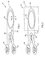
- FIGS. 1-7 there is shown an embodiment of a reduced power consumption gas chromatograph system 10 in accordance with the invention which is particularly useful in miniature and portable gas chromatograph instruments.
- the reduced power consumption is embodied by a unique packing and location scheme of a capillary gas chromatograph column member 12 in combination with a temperature sensing means 14 and a heating means 16 which, as will be shown in following paragraphs, substantially increases the internal contact of such components with themselves and each other while simultaneously reducing the amount of surface area of these components in contact with the external environment to reduced operational power requirements.
- the reduced power consumption gas chromatograph system 10 includes in general, injection device 18 for introducing chemical samples into gas chromatograph column assembly 20 comprised of gas chromatograph column member 12, temperature sensing means 14, and heating means 16.
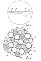
- gas chromatograph column assembly 20 is clearly seen in FIG. 3 .
- Detection device 22 is coupled to the exit section of gas chromatograph column assembly 20 and measures, as well as analyzes chemicals present in the vapor exiting gas chromatograph column assembly 20.
- a programmable computer 24 is coupled into system 10 to provide control of injection device 18, detection device 22, as well as the parameters associated with reduced low power consumption gas chromatograph system 10 within gas chromatograph column assembly 20.
- the subject reduced power consumption chromatograph system 10 is contemplated for use with a number of well-known injection devices 18, detection devices 22, as well as possibly remote monitors.
- computer 24, injection device 18, and detection device 22 as well as the electronics packages associated therewith may assume a variety of circuit and structural configurations well-known in the art which are not germane to the present invention with the exception that they provide proper chemical samples to gas chromatograph column assembly 20 as well as appropriate heating and control mechanisms.
- any electronics packages, computer 24, detection device 22, or injection device 18 will be omitted since they do not form a part of the subject invention concept.
- gas chromatograph column assembly 20 is generally heated and maintained at elevated temperatures to prevent stoppage or slowing of analytes through possible cold spots in gas chromatograph column assembly 20, however, such heaters are well-known in the art and may at times even be included with injection device 18 and detection device 22, but are not depicted in the Figures since such do not form part of the invention concept as herein described.
- gas chromatograph column assembly 20 which includes lead section 26 (both entry and egress sections being labelled with the same element number), and coiled section 28 of gas chromatograph column assembly 20.
- Lead sections 26 and coiled sections 28 are composed of gas chromatograph column member 12, temperature sensing means 14, and heating means 16, as is shown in FIG. 3 .
- Capillary gas chromatograph column member 12 has a predetermined length containing a chemical sample therein.
- Gas chromatograph column member 12 may be formed of a fused silica or some like material.
- Heating means 16 heats the chemical sample contained within gas chromatograph column member 12. Heating means 16 may be positionally located around capillary chromatograph column member 12, as is shown in FIG. 3 . Heating means 16 may take the form of an insulated wire member wound around gas chromatograph column member 12 in a co-axial manner and in particular may be helically wound around the combination of gas chromatograph column 12 and temperature sensing means 14, as further shown in FIG. 3 . A winding of heating means or heater wire 16 reduces the difficulty in handling the components when hand coiling of coiled section 28 is accomplished. In general, heating wire or heating means 16 may correspond to a pitch of 10o or less for the helical winding.
- Heater wires 16 in actual use may be composed of 0.005" (0.0127 cm) diameter Chromel wire having approximately 0.003" (0.00762 cm) insulation formed on the exterior of the heater wire 16. Use of such insulated wire members 16 is advantageous in that such provides a low thermal mass per unit length.
- Temperature sensing means 14 forming a component of gas chromatograph column assembly 20 measures the temperature of the gas sample contained within capillary chromatograph column member 12 with the temperature sensing means 14, in the preferred embodiment, extending substantially throughout the predetermined length of, and located adjacent gas chromatograph column member 12, as is shown in FIG. 3 . As is seen, temperature sensing means 14 may be located in adjacent positional relationship with capillary gas chromatograph column member 12 and may be mounted within the wound coils of heating wire 16. Experimentation with differing types of temperature sensing means 14 show that low power results could be achieved using a number of well-known temperature sensing means 14 as long as the particular temperature sensors were of a low thermal mass design.
- Such temperature sensing means 14 applicable to reduced power consumption gas chromatograph system 10 include resistance temperature devices such as alloys in the form of insulated fine wires which provide for a change in resistance as a function of temperature. Resistance temperature devices generally provide a distributed measurement of the temperature along the entire length of the temperature sensor. It is within the scope of this invention to use other types of temperature sensing elements providing a more local or point measurement of the temperature and such may be in the form of a thermocouple used in place of the temperature sensor element shown in the Figures. In such a configuration, gas chromatograph column assembly 20 would consist of capillary gas chromatograph column member 12, heater mechanism or heater wire 16, and a point temperature sensor introduced in the coiled section 28 of column assembly 20 to measure the temperature of the coiled components.
- thermocouples having larger thermal masses such as thermocouples are formed of approximately 0.010" (0.0254cm) diameter wires was found during experimentation to slightly increase the power requirements required for temperature programming of very low thermal mass assemblies which is the result of larger heats required to raise such temperatures to a local temperature.
- coiled section 28 of column assembly 20 is enclosed within enclosure housing 30.
- enclosure housing 30 encapsulates coiled section 28 of gas chromatograph column assembly 20 and may be in the form of a sheath formed around coiled section 28.
- Sheath or enclosure housing 30 may be formed with foil wrappings of coiled section 28 as well as placement of coiled section 28 within thermally insulating materials.
- Thermally insulating materials forming enclosure housing 30 were tested in the form of high thermal protection composite fiber ceramic insulation commercially available from Lockheed Missiles and Space Company located in Sunnyvale, California.
- High thermal protection composite fiber ceramic insulation having a designation HTP-16 was used successfully in providing low power consumption and such included a low thermal conductivity approximating 0.54 Btu-in./ft. 2 -hr.-oF (0.078 W/mK), with a low specific heat approximating 0.2 Btu per/lb.-oF (837.36 J/kgK).
- FIG. 2 An embodiment of reduced power consumption gas chromatograph system 10' is shown in FIG. 2 where gas chromatograph column assembly 20 is contained within vacuum container 32 for the purposes of increasing thermal isolation between gas chromatograph column assembly 20 and the external environment.
- the identical capillary gas chromatograph column assemblies 20 were placed in a 1.0 meter length of Teflon tubing having an inner diameter approximating 0.063" (0.160 cm) and a wall thickness approximating 0.012" (0.030 cm) following the designs of the prior art Holland, et al. systems (1995 ) previously discussed.
- the low power gas chromatograph capillary column assembly 20 was temperature programmed by using a heater circuit in which the temperature sensor 14 served as a feedback control element.
- the circuit applied a current to the heater wire 16 as long as the temperature sensed by the temperature sensor 14 was below a target temperature.
- the heater circuit then followed the computer-generated ramp resulting in a temperature program ramp of the subject gas chromatograph capillary column assembly 20.
- a temperature program using the heater circuit was selected to simulate the temperature program used by the prior art Maswadeh, et al. (1996) previously discussed.
- the current required by the heater circuit was measured using a digital ammeter and recorded in a processor and the average power required during a thirty second heating ramp was then calculated.
- Tables 1 and 2 summarize the average power required for 0.75oC/s for (1) a temperature program from 32oC - 55oC and (2) a temperature program from 32oC - 180oC.
- the average power required for these conditions is summarized in the following Tables: TABLE 1 POWER REQUIRED FOR 0.75°C/s FROM 32°C - 55°C TYPE AVERAGE POWER (WATTS) Subject System with Foil Wrap in Air 0.52 Subject System with Foil Wrap in Vacuum 0.53 Subject System within Insulated Housing Material 0.60 Prior Art System, Holland, et al. (1995) Using Teflon-Tubing Jacketed Components 3.4 Prior Art System for Low Power Gas Chromatograph System of Maswadeh, et al. (1996) 15.0
- Table 1 clearly indicates that the power required is a factor of 30 lower than the low power temperature programming results achieved by the prior art Maswadeh, et al. (1996) system. An 85% reduction in power was also demonstrated relative to the low power, tubing-jacketed designs reported by the prior art Holland, et al. (1995) systems. Similar results are obtained with the subject reduced power consumption gas chromatograph system 10 in air and in vacuum using a foil wrapped packed coil assembly 20. Power requirements using the insulating enclosure was also seen to be low with an average power of .60 watts but not as low as the foil wrapped assembly 20 which showed an average power of 0.52 in air and 0.53 in vacuum.
- the temperature program used for the results in Table 1 was limited to relatively low temperatures for the gas chromatography-ion mobility spectrometer application described in the prior art Maswadeh, et al. (1996) system. Larger temperature ranges are generally used in programming to achieve a wider range of chemical separations using gas chromatography. However, as the programming temperatures increase relative to the ambient temperatures, heat conduction to the surroundings increases and the resulting power required for programming also rises. In order to demonstrate the low power requirements of the subject reduced power consumption gas chromatograph system 10, the upper temperature limit of the programs used were extended to 180oC. The average power results are summarized in the following Table 2 which once again shows a dramatic decrease in the average power between the known prior art and the subject invention concept.
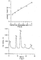
- FIG. 5 such provides a temperature sensor output and power vs. time for heating of the foil wrapped gas chromatographic capillary column assembly 20 in air at a rate of 0.75oC/s shown as the initial example in Table 2.
- FIG. 5 is directed to the raw data for the instantaneous power used by the internal heater wire 16 in the lower portion of the graph.
- the temperature programmed ramp reported by the temperature sensor 14 is shown in the upper trace of the graph.
- the temperature ramp is substantially linear and the average power consumed during the ramp is approximately 2.0 watts. Since the ramping rate was the same as the rate used for the experiments shown in Table 1, integration and averaging of the power during the first thirty seconds of this ramp resulted in a power approximating 0.5 watts as shown in Table 1.
- the average power required during a temperature program increases with increasing ramping rates.
- the average power required for the foil wrapped low power gas chromatograph capillary column assembly 20 in air at different ramping rates between 32oC and 180oC is shown in the graph of FIG. 6 .
- Relatively small increases in the average power are required for large increases in the temperature programming rate for such an assembly.
- fast temperature programming rates can consume less total power.
- the subject system 10 reduces average power requirements to a level that allows fast ramping possible even in battery-operated portable instruments which further reduces the total power requirements while increasing the speed of temperature programmed analyses.
- FIG. 6 An example of fast chromatography using a 1 meter, HTP-insulation enclosed low power gas chromatography capillary column assembly 20 is shown in FIG. 6 .
- the assembly contained a 1 meter Sulfur-AT column member purchased from Alltech Associates, Inc. of Deerfield, Illinois having an internal diameter approximating 0.32 mm.
- a column flow rate of 10 mL/min of helium was used for chromatography with this short column which was directly connected to a flame ionization detector.
- a temperature program of 2oC/s for 30 seconds duration was used with a starting temperature of 40oC.
- Such conditions provided fast, low resolution separation of semi-volatile alkane hydrocarbons between nonane (C 9 ) and dodecane (C 12 ) in less than 30 seconds.
Landscapes
- General Health & Medical Sciences (AREA)
- Life Sciences & Earth Sciences (AREA)
- Chemical & Material Sciences (AREA)
- Analytical Chemistry (AREA)
- Biochemistry (AREA)
- Immunology (AREA)
- General Physics & Mathematics (AREA)
- Health & Medical Sciences (AREA)
- Pathology (AREA)
- Physics & Mathematics (AREA)
- Other Investigation Or Analysis Of Materials By Electrical Means (AREA)
- Sampling And Sample Adjustment (AREA)
- Treatment Of Liquids With Adsorbents In General (AREA)
- Solid-Sorbent Or Filter-Aiding Compositions (AREA)
Abstract
Description
- The present invention relates to gas chromatography systems, for example for generally continuously sampling chemical samples and detecting desired compounds therefrom.
- High performance gas chromatography has typically required the use of large laboratory instruments using large amounts of electrical power in their operation. This is especially the case for the standard practice of temperature programming a chromatographic separation in which the temperature of the oven containing the gas chromatography column is steadily increased to extend the range of gas chromatography separation capability. The large power required to heat and temperature program gas chromatography ovens has limited the capability of gas chromatography for use in portable instrumentation and especially in hand-portable instrumentation used in the field. Without large external power sources or large batteries, gas chromatography design and operations have been limited largely to non-temperature programming applications in small, lightweight portable instruments.
- Additional requirements for gas chromatography technology to be practical in small portable instruments is for the technology to be compatible with and use commercially available gas chromatography capillary column technology. Since the use of capillary columns has become standard practice in laboratory gas chromatography instrumentation, a large number of capillary columns are now commercially available which offer a wide range of separation capabilities. The wide range of separation capabilities has been made possible through variation of the chemical compositions of the polymers which coat the inner walls of the capillary gas chromatography columns. Choice may now be had from many polymer coatings that are commercially available in capillary gas chromatography columns having standard thicknesses, column lengths, and column inner diameters to optimize the chemical separations required of the gas chromatography. The ability to readily use this commercially available gas chromatography column technology in small portable gas chromatography instruments is desirable for the practical realization of similar analytical capabilities in portable or small gas chromatography instruments.
- The temperature programming of capillary gas chromatography columns is standardly practiced by electronic control of the temperature of an oven containing the gas chromatography column. To achieve rapid and uniform temperature response of the gas chromatography column assembly to temperature changes in the oven, capillary gas chromatography columns are standardly packaged by winding the columns on a wire frame support. The winding of the columns on the wire frame support provides extensive surface contact of the capillary gas chromatography column with the heated air in the oven for rapid temperature equilibration of the capillary gas chromatography column with the oven air. In laboratory gas chromatography ovens, the air within the oven is typically mixed with a fan to achieve temperature uniformity within the oven. Laboratory gas chromatography instruments typically consume power on the order of kilowatts for temperature programming and are power limited to temperature ramping rates approximating 10's of oC/min or less,especially at higher operating temperatures. While smaller, more portable gas chromatography instruments have been manufactured which have smaller ovens, such still require powers on the order of 1 kW or more for temperature programming, especially when ramping rates of 10's of oC/min are required for fast analysis times.
- Reductions in gas chromatography oven size to that of a small heated compartment large enough to contain a short length of gas chromatography column have been made for the purposes of reducing power consumption and reducing instrument size. The resulting gas chromatography instruments are typically operated isothermally to avoid the power consumption associated with temperature programming, but this greatly constrains the analytical capabilities of such gas chromatography instrumentation. One case in which low power temperature programming has been implemented is described by Maswadeh et al. in "New Generation of Hand-Held, Compact, Disposable Gas Chromatography Devices," Field-Portable Chromatography and Spectrometry workshop, June 3-5, 1996, Snowbird, UT, pp. P56-P59. In this case a palm-size gas chromatography module was demonstrated which consumes 15W of power for temperature programming at a 0.75oC/s ramp rate. A short ramp with a maximum temperature of 60oC served to limit power consumption by the module.
- The need for fast temperature programming of miniature chromatographic analysis instrumentation is described by
Sides and Cates in U.S. Patent #5,014,541 . They describe the requirement to raise the temperature of the capillary gas chromatography column from 50oC to 120oC within 20 seconds to achieve their analysis objectives. They accomplish this with a miniature gas chromatography column assembly in which the standard gas chromatography oven is replaced by a tubular heat conductor support on which the gas chromatography column is wound. A heating element within the tubular support is used for temperature programming. While this instrument achieves a gas chromatograph of small size, the power consumption is on the order of 1 kW and a portable power generator is a recommended option for portable operation of this commercial instrument. - The importance of reducing the thermal mass of gas chromatography column assemblies for the rapid heating was recognized by
Norem in U.S. Patent #3,159,996 . This invention consisted of a glass tube with three parallel bores and sufficient length to contain a heater wire, a resistance thermometer wire (a type of temperature sensor), with the remaining bore coated on the inside to function as a gas chromatography column. While such a device could have a smaller thermal mass than a small, conventional gas chromatography oven, a large amount of power will still be required to heat the sizable mass of glass tubing. - Another way to significantly reduce power consumption with a miniature gas chromatography is by reducing the electrical heating and sensing elements of gas chromatography ovens to miniature forms and integrate them with a capillary gas chromatography column.
U.S. Patent #5,005,399 achieves this by using a thin-film coated capillary gas chromatography column wound on a mandrill consisting of an insulating material. Electrical current passed through the thin film surrounding the gas chromatography column is used to resistively heat the column. While this approach uses far less power than heating a conventional gas chromatography oven, it still requires significant power to heat the gas chromatography column because of the large surface area of the gas chromatography column in contact with the mandrill material since this insulating support is also heated through contact with the heating element. A serious shortcoming of this approach is the difficulty of fabricating annular thin film coatings of substantial length having sufficient uniformity and freedom from defects. The thermal mass of the gas chromatography column plus contacting insulation is large enough that currents on the order of 1 ampere or more are typically required for fast temperature programming using battery voltages such as 12 volts. The conduction of such large currents in thin film resistive heaters requires the films to be substantially free of defects. While thickness non-uniformity results in uneven heating, typical defects in thin films due to microcontamination, particulates, abrasion from handling, or stresses and fractures due to bending (such as coiling the column) cause local hot spots and thin film breakdown resulting in failure of the heater element. A further difficulty with this approach is that it is not compatible with the use of commercially available gas chromatography column technology; special thin film resistor-coated versions of each gas chromatography column of interest would have to be manufactured requiring large scale, omnidirectional precision deposition of very high quality films. Given the technical problems with the handling, operating and manufacturing of precision thin film resistive heaters of this scale, this is a serious difficulty. - While not claiming low power operation, a similar approach by U.S. Patent #4,726,822 relies on annular thin film heater and insulator layers to miniaturize a heated capillary gas chromatography column assembly. In addition to the handling, operating and manufacturing impracticalities discussed in the preceding paragraph with respect to U.S. Patent #5,005,399, the close spacing of multiple thin films present additional difficulties.
- Another approach to reducing power consumption by a capillary gas chromatography column assembly has been published by Holland, et al. in "Handheld Gas Chromatography Instrumentation for Chemical Weapons Convention Treaty Verification Instrumentation," Field Screening Methods for Hazardous Wastes and Toxic Chemicals, Vol. 1, Air & Waste Management Association, Pittsburgh, 1995, pp. 229-235. In this approach a gas chromatography capillary column is placed inside a length of small plastic tubing along with coaxial heater and sensor wires. This gas chromatography assembly uses far less power than the power required by commercial gas chromatography ovens. Typical powers required for temperature programming this assembly are still on the order of 10's of watts per meter of column length for fast, short gas chromatography column configurations reported by Overton and Carney in "New Horizons in Gas Chromatography: Field Applications of Microminiaturized Gas Chromatographic Techniques," Trends in Analytical Chemistry, Vol. 13, 1994, pp. 252-257, and by Overton, et al. in "A New Portable Micro Gas Chromatograph for Environmental Analysis," in Field Screening Methods for Hazardous Wastes and Toxic Chemicals, Vol. 1, Air & Waste Management Association, Pittsburgh, 1995, pp. 207-212. Much lower power consumption is required for battery powered fast temperature programming by small portable gas chromatography instruments. While this approach permits the use of commercially available gas chromatography capillary columns, the difficulty of threading capillary gas chromatography columns, heater wires, and sensor wires into small plastic tubing limits the practical assembly lengths to several meters.
- EHRMANN E. U. et al: "Novel Column Heater for Fast Capillary Gas Chromatography", Journal of Chromatographic Science, US, NILES, IL, vol.34, December 1996, pages 533-539, disclose two different types of heating systems, a coaxial heater and a collinear heater. The coaxial heater comprises a capillary column inserted along with the same length of an electrically insulated nickel alloy sensor wire into a piece of silver-plated stainless steel tubing. For electrical insulation between column coils, the whole assembly itself is inserted into a piece of Teflon tubing. The collinear heater was built using nickel alloy wire as the heating element instead of the stainless steel tubing. In this system, the column, sensor wire, and heater wire were inserted together into a Teflon tube.
-
WO91/00131 - R. J. LLOYD: Journal of Chromatography, vol. 284, no. 2, February 1984, pages 357-371, Elsevier Science Publishers B.V. Amsterdam, NL, ISSN: 0021-9673, disclose instrumentation to perform automated thermal desorption-pyrolysis capillary gas chromatography. The evolved compounds are cryogenically trapped to minimize peak width and to isolate the chromatographic column from reactive atmospheres, if necessary. The instrument is operated in the splitless mode to maximize sensitivity.
-
FR-2,637,685 -
EP 0445967 discloses gas chromatographic methods and apparatus whereby improved separation times and efficiency are achieved by provision of a rapid transfer of heat or cooling from a heating or cooling source to a chromatographic column. The column is provided within an insulating sheath. A resistance heating element disposed in the sheath and optional heated or cooling gas flow through the sheath is capable of rapidly changing the temperature imparted to the column thereby. - According to the present invention, there is provided a gas chromatograph system as specified in claim 1.
- Particular and preferred aspects of the invention are set out in the accompanying dependent claims. Features of the dependent claims may be combined with those of the independent claim as appropriate.
- An embodiment of the invention can provide a gas chromatograph column assembly which achieves fast, temperature programming rates with a low power consumption.
- An embodiment of the invention can provide an innovative packing of a capillary gas chromatograph column member with a temperature sensor and heater wires to increase the internal contact of such components within a coiled section while reducing the fraction of each component surface area exposed at the periphery of the coiled section.
- An embodiment of the invention can optimally reduce the amount of the packed component's surface area within the coiled section which is exposed directly to air or insulating surroundings.
- An embodiment of the invention can allow heat exchange and conservation of energy within the packed combination of a gas chromatography column member, heating mechanism and temperature sensing mechanism.
- An embodiment of the invention can provide an overall gas chromatography column assembly internally heated and consisting of a packed, low thermal mass set of components in which the outer surface of the assembly has a small surface area compared to the total surface area of the components within the assembly for reducing both the heat loss to the surroundings and the heat required to raise the temperature of the components.
- An embodiment of the invention can provide a system having the ability to readily incorporate any standard commercially available gas chromatography capillary column member into a low power miniature gas chromatography column assembly.
- An embodiment of the invention can provide a gas chromatographic column assembly temperature programmed analyses. Power savings can be achieved through optimized packing of capillary gas chromatograph column members with temperature sensors and heating wires which substantially increases the internal contact of such components with themselves and each other while reducing the amount of surface area of these components in contact with the surroundings. An embodiment of the invention can also provide a gas chromatograph system which includes assemblies of capillary gas chromatograph column members, temperature sensing means and heating means formed into a gas chromatograph column assembly which is positionally located in a manner to optimize thermal effects and produce an overall low power consumption system.
- Exemplary embodiments of the invention are described hereinafter, by way of example only, with reference to the accompanying drawings, in which:
-
FIG. 1 is a schematic representation of an embodiment of a reduced power consumption gas chromatograph system showing a coiled section in a gas chromatograph column assembly; -
FIG. 2 is a schematic representation of an embodiment of the reduced power consumption gas chromatograph system shown inFIG. 1 wherein the coiled section of the gas chromatograph column assembly is located within a vacuum environment; -
FIG. 3 is a schematic representation of a lead section of the gas chromatograph column assembly showing the components thereof; -
FIG. 4 is a cross-section of the coiled section of the gas chromatograph column assembly taken along the Section Line 4-4 ofFIG. 1 ; -
FIG. 5 is a graph of the reduced power consumption gas chromatograph system showing temperature programming of a low power gas chromatograph capillary column assembly from 32oC - 180oC at a rate of 0.75oC/s; -
FIG. 6 is a graph showing average power required to temperature program a linear ramp between 32oC - 180oC with the reduced power consumption gas chromatograph system for a plurality of different temperature programming rates; and, -
FIG. 7 is a graph showing a fast gas chromatography data for the separation of some semi-volatile alkane hydrocarbons using the subject reduced power consumption gas chromatograph system. - Referring now to
FIGS. 1-7 , there is shown an embodiment of a reduced power consumptiongas chromatograph system 10 in accordance with the invention which is particularly useful in miniature and portable gas chromatograph instruments. In overall concept, the reduced power consumption is embodied by a unique packing and location scheme of a capillary gaschromatograph column member 12 in combination with a temperature sensing means 14 and a heating means 16 which, as will be shown in following paragraphs, substantially increases the internal contact of such components with themselves and each other while simultaneously reducing the amount of surface area of these components in contact with the external environment to reduced operational power requirements. - The reduced power consumption
gas chromatograph system 10 includes in general,injection device 18 for introducing chemical samples into gaschromatograph column assembly 20 comprised of gaschromatograph column member 12, temperature sensing means 14, and heating means 16. The components of gaschromatograph column assembly 20 is clearly seen inFIG. 3 . -
Detection device 22 is coupled to the exit section of gaschromatograph column assembly 20 and measures, as well as analyzes chemicals present in the vapor exiting gaschromatograph column assembly 20. A number of commerciallyavailable detection devices 22 exist and are not important to the inventive concept as herein described, however, such may include flame ionization, flame photometry, mass spectrometry, ion mobility, electron capture, and other ionization techniques. - A
programmable computer 24 is coupled intosystem 10 to provide control ofinjection device 18,detection device 22, as well as the parameters associated with reduced low power consumptiongas chromatograph system 10 within gaschromatograph column assembly 20. - It is to be understood that the subject reduced power
consumption chromatograph system 10 is contemplated for use with a number of well-knowninjection devices 18,detection devices 22, as well as possibly remote monitors. However,computer 24,injection device 18, anddetection device 22 as well as the electronics packages associated therewith may assume a variety of circuit and structural configurations well-known in the art which are not germane to the present invention with the exception that they provide proper chemical samples to gaschromatograph column assembly 20 as well as appropriate heating and control mechanisms. Thus, in the interest of clarity, further discussion of any electronics packages,computer 24,detection device 22, orinjection device 18 will be omitted since they do not form a part of the subject invention concept. Additionally, the entrance and exit regions of gaschromatograph column assembly 20 are generally heated and maintained at elevated temperatures to prevent stoppage or slowing of analytes through possible cold spots in gaschromatograph column assembly 20, however, such heaters are well-known in the art and may at times even be included withinjection device 18 anddetection device 22, but are not depicted in the Figures since such do not form part of the invention concept as herein described. - Referring specifically to
FIGS. 1 ,3, and 4 , there is shown gaschromatograph column assembly 20 which includes lead section 26 (both entry and egress sections being labelled with the same element number), andcoiled section 28 of gaschromatograph column assembly 20. Leadsections 26 and coiledsections 28 are composed of gaschromatograph column member 12, temperature sensing means 14, and heating means 16, as is shown inFIG. 3 . Capillary gaschromatograph column member 12 has a predetermined length containing a chemical sample therein. Gaschromatograph column member 12 may be formed of a fused silica or some like material. - Heating means 16 heats the chemical sample contained within gas
chromatograph column member 12. Heating means 16 may be positionally located around capillarychromatograph column member 12, as is shown inFIG. 3 . Heating means 16 may take the form of an insulated wire member wound around gaschromatograph column member 12 in a co-axial manner and in particular may be helically wound around the combination ofgas chromatograph column 12 and temperature sensing means 14, as further shown inFIG. 3 . A winding of heating means orheater wire 16 reduces the difficulty in handling the components when hand coiling of coiledsection 28 is accomplished. In general, heating wire or heating means 16 may correspond to a pitch of 10o or less for the helical winding. Pitches of 10o or less were not found to adversely affect the power requirements for low power consumptiongas chromatograph assemblies 20, however, extensive winding ofheater wires 16 at pitch angles greater than about 20o resulted in increased power consumption by the gaschromatograph column assembly 20.Heater wires 16 in actual use may be composed of 0.005" (0.0127 cm) diameter Chromel wire having approximately 0.003" (0.00762 cm) insulation formed on the exterior of theheater wire 16. Use of suchinsulated wire members 16 is advantageous in that such provides a low thermal mass per unit length. - Temperature sensing means 14 forming a component of gas
chromatograph column assembly 20 measures the temperature of the gas sample contained within capillarychromatograph column member 12 with the temperature sensing means 14, in the preferred embodiment, extending substantially throughout the predetermined length of, and located adjacent gaschromatograph column member 12, as is shown inFIG. 3 . As is seen, temperature sensing means 14 may be located in adjacent positional relationship with capillary gaschromatograph column member 12 and may be mounted within the wound coils ofheating wire 16. Experimentation with differing types of temperature sensing means 14 show that low power results could be achieved using a number of well-known temperature sensing means 14 as long as the particular temperature sensors were of a low thermal mass design. Such temperature sensing means 14 applicable to reduced power consumptiongas chromatograph system 10 include resistance temperature devices such as alloys in the form of insulated fine wires which provide for a change in resistance as a function of temperature. Resistance temperature devices generally provide a distributed measurement of the temperature along the entire length of the temperature sensor. It is within the scope of this invention to use other types of temperature sensing elements providing a more local or point measurement of the temperature and such may be in the form of a thermocouple used in place of the temperature sensor element shown in the Figures. In such a configuration, gaschromatograph column assembly 20 would consist of capillary gaschromatograph column member 12, heater mechanism orheater wire 16, and a point temperature sensor introduced in the coiledsection 28 ofcolumn assembly 20 to measure the temperature of the coiled components. Substitution of temperature sensors having larger thermal masses such as thermocouples are formed of approximately 0.010" (0.0254cm) diameter wires was found during experimentation to slightly increase the power requirements required for temperature programming of very low thermal mass assemblies which is the result of larger heats required to raise such temperatures to a local temperature. - As shown in
FIG. 4 , coiledsection 28 ofcolumn assembly 20 is enclosed withinenclosure housing 30. In this manner, coiledsection 28 of gaschromatograph column assembly 20 is thermally isolated from an external environment.Enclosure housing 30 encapsulates coiledsection 28 of gaschromatograph column assembly 20 and may be in the form of a sheath formed around coiledsection 28. - Sheath or
enclosure housing 30 may be formed with foil wrappings of coiledsection 28 as well as placement of coiledsection 28 within thermally insulating materials. Thermally insulating materials formingenclosure housing 30 were tested in the form of high thermal protection composite fiber ceramic insulation commercially available from Lockheed Missiles and Space Company located in Sunnyvale, California. High thermal protection composite fiber ceramic insulation having a designation HTP-16 was used successfully in providing low power consumption and such included a low thermal conductivity approximating 0.54 Btu-in./ft.2-hr.-oF (0.078 W/mK), with a low specific heat approximating 0.2 Btu per/lb.-oF (837.36 J/kgK). - An embodiment of reduced power consumption gas chromatograph system 10' is shown in
FIG. 2 where gaschromatograph column assembly 20 is contained withinvacuum container 32 for the purposes of increasing thermal isolation between gaschromatograph column assembly 20 and the external environment. - A series of tests were run for reduced power consumption
gas chromatograph system 10 or 10' where coiledsection 28 of gaschromatograph column assembly 20 included a sheath orhousing 30 formed of a foil wrap as previously described in an open air environment, a foil wrap contained within a vacuum, andassembly 20 having an insulating housing material as previously discussed. For the experimentation with the high thermal protection composite fiber ceramic insulation, the packedcoil assembly 28 was placed between 2x2x0.5" (5.08 x 5.08 x 1.27 cm) pieces of HTP-16 with each of the pieces containing a circular groove to hold the packedcoil assembly 28. In order for the insulated enclosure assembly to cool quickly so that another temperature programmed analysis may be started, it is necessary to cool the heated components at the end of a temperature programmed analysis. It was found that small openings of approximately 1-2 mm in diameter in the enclosures placed along the path of a circular groove containing the packedcoil 28 of gas chromatographcapillary column assembly 20 provided sufficient air passages with a miniature electric fan being used to allow rapid cooling. The introduction of the openings through the insulating enclosures was not found to significantly increase the power required for temperature programming of the capillary gaschromatograph column assembly 20. For comparison with the power requirements for tubing-jacketed gas chromatograph column designs, the identical capillary gaschromatograph column assemblies 20 were placed in a 1.0 meter length of Teflon tubing having an inner diameter approximating 0.063" (0.160 cm) and a wall thickness approximating 0.012" (0.030 cm) following the designs of the prior art Holland, et al. systems (1995) previously discussed. - The low power gas chromatograph
capillary column assembly 20 was temperature programmed by using a heater circuit in which thetemperature sensor 14 served as a feedback control element. The circuit applied a current to theheater wire 16 as long as the temperature sensed by thetemperature sensor 14 was below a target temperature. By using a computer-generated voltage ramp for the target temperature, the heater circuit then followed the computer-generated ramp resulting in a temperature program ramp of the subject gas chromatographcapillary column assembly 20. A temperature program using the heater circuit was selected to simulate the temperature program used by the prior art Maswadeh, et al. (1996) previously discussed. The current required by the heater circuit was measured using a digital ammeter and recorded in a processor and the average power required during a thirty second heating ramp was then calculated. The following Tables 1 and 2 summarize the average power required for 0.75oC/s for (1) a temperature program from 32oC - 55oC and (2) a temperature program from 32oC - 180oC. The average power required for these conditions is summarized in the following Tables:TABLE 1 POWER REQUIRED FOR 0.75°C/s FROM 32°C - 55°C TYPE AVERAGE POWER (WATTS) Subject System with Foil Wrap in Air 0.52 Subject System with Foil Wrap in Vacuum 0.53 Subject System within Insulated Housing Material 0.60 Prior Art System, Holland, et al. (1995) Using Teflon-Tubing Jacketed Components 3.4 Prior Art System for Low Power Gas Chromatograph System of Maswadeh, et al. (1996) 15.0 - Table 1 clearly indicates that the power required is a factor of 30 lower than the low power temperature programming results achieved by the prior art Maswadeh, et al. (1996) system. An 85% reduction in power was also demonstrated relative to the low power, tubing-jacketed designs reported by the prior art Holland, et al. (1995) systems. Similar results are obtained with the subject reduced power consumption
gas chromatograph system 10 in air and in vacuum using a foil wrapped packedcoil assembly 20. Power requirements using the insulating enclosure was also seen to be low with an average power of .60 watts but not as low as the foil wrappedassembly 20 which showed an average power of 0.52 in air and 0.53 in vacuum. - The temperature program used for the results in Table 1 was limited to relatively low temperatures for the gas chromatography-ion mobility spectrometer application described in the prior art Maswadeh, et al. (1996) system. Larger temperature ranges are generally used in programming to achieve a wider range of chemical separations using gas chromatography. However, as the programming temperatures increase relative to the ambient temperatures, heat conduction to the surroundings increases and the resulting power required for programming also rises. In order to demonstrate the low power requirements of the subject reduced power consumption
gas chromatograph system 10, the upper temperature limit of the programs used were extended to 180oC. The average power results are summarized in the following Table 2 which once again shows a dramatic decrease in the average power between the known prior art and the subject invention concept.TABLE 2 POWER REQUIRED FOR 0.75°C/s FROM 32°C - 180°C TYPE AVERAGE POWER (WATTS) Subject System with Foil Wrap in Air 2.0 Subject System with Foil Wrap in Vacuum 1.6 Subject System Within Insulated Housing Material 2.6 Subject System Without Enclosure Sheath in Air 3.1 Prior Art System, Holland, et al. (1995) Using Teflon-Tubing Jacketed Components 18.0 - Referring to
FIG. 5 , such provides a temperature sensor output and power vs. time for heating of the foil wrapped gas chromatographiccapillary column assembly 20 in air at a rate of 0.75oC/s shown as the initial example in Table 2.FIG. 5 is directed to the raw data for the instantaneous power used by theinternal heater wire 16 in the lower portion of the graph. The temperature programmed ramp reported by thetemperature sensor 14 is shown in the upper trace of the graph. The temperature ramp is substantially linear and the average power consumed during the ramp is approximately 2.0 watts. Since the ramping rate was the same as the rate used for the experiments shown in Table 1, integration and averaging of the power during the first thirty seconds of this ramp resulted in a power approximating 0.5 watts as shown in Table 1. - As is known, the average power required during a temperature program increases with increasing ramping rates. The average power required for the foil wrapped low power gas chromatograph
capillary column assembly 20 in air at different ramping rates between 32oC and 180oC is shown in the graph ofFIG. 6 . Relatively small increases in the average power are required for large increases in the temperature programming rate for such an assembly. Because of the shorter time for heat conduction to the surroundings, fast temperature programming rates can consume less total power. Importantly, thesubject system 10 reduces average power requirements to a level that allows fast ramping possible even in battery-operated portable instruments which further reduces the total power requirements while increasing the speed of temperature programmed analyses. - An example of fast chromatography using a 1 meter, HTP-insulation enclosed low power gas chromatography
capillary column assembly 20 is shown inFIG. 6 . The assembly contained a 1 meter Sulfur-AT column member purchased from Alltech Associates, Inc. of Deerfield, Illinois having an internal diameter approximating 0.32 mm. A column flow rate of 10 mL/min of helium was used for chromatography with this short column which was directly connected to a flame ionization detector. A temperature program of 2oC/s for 30 seconds duration was used with a starting temperature of 40oC. Such conditions provided fast, low resolution separation of semi-volatile alkane hydrocarbons between nonane (C9) and dodecane (C12) in less than 30 seconds. - Although a specific embodiment of the invention has been described, it will be appreciated that various modifications other than those discussed above may be resorted to without departing from the scope of the invention. For example, functionally equivalent elements may be substituted for those specifically shown and described, proportional quantities of the elements shown and described may be varied, and in the formation method steps described, particular steps may be reversed or interposed, all without departing from the scope of the invention.
Claims (12)
- A gas chromatograph system comprising a gas chromatograph column assembly (20) which includes a lead section (26) and a coiled section (28), wherein:said gas chromatograph column assembly comprises:(a) a capillary gas chromatograph column member (12) having a predetermined length containing a chemical sample therein;(b) temperature sensing means (14) for measuring a temperature of said chemical sample contained within said capillary chromatograph column member ;
and(c) heating means (16) for heating said chemical sample contained within said gas chromatograph column member, wherein said temperature sensing means and said heating means are located adjacent said gas chromatograph column member in said coiled section, and wherein said heating means includes an insulated wire member wound around said gas chromatograph column member in a coaxial manner; whereinsaid coiled section of said gas chromatograph column assembly comprises a circular packed coil assembly that includes at least two coils of said combination of said gas chromatograph column, said temperature sensing means and said heating means and is enclosed within an enclosure housing (30) so as to be thermally isolated from an external environment; andas seen in a cross-section of said circular packed coil assembly, said at least two coils of the combination of gas chromatograph column, temperature sensing means and heating means are located adjacent to each other within the same closed space formed by said enclosure housing. - A gas chromatograph system according to Claim 1, wherein said temperature sensing means extends substantially throughout said predetermined length of said chromatograph column member.
- A gas chromatograph system according to Claim 1 or Claim 2, wherein said insulated wire member is helically wound around said gas chromatograph column member substantially throughout said predetermined length.
- A gas chromatograph system according to Claim 3, wherein said insulated wire member has a pitch approximating 10° when wound around said gas chromatograph column member.
- A gas chromatograph system according to Claim 4, wherein said insulated wire member is formed of a material having a low thermal mass per unit length.
- A gas chromatograph system according to any preceding claim, wherein said temperature sensing means is located in axially aligned relationship with said capillary gas chromatograph column member.
- A gas chromatograph system according to Claim 6, wherein said temperature sensing means includes means for distributed temperature measurement throughout at least a portion of a length of said temperature sensing means.
- A gas chromatograph system according to Claim 6 or Claim 7, wherein said temperature sensing means is a resistance thermal device.
- A gas chromatograph column assembly according to any preceding Claim, wherein said enclosure housing is formed of a thermally insulating material.
- A gas chromatograph column assembly according to Claim 10, wherein said enclosure housing is a sheath formed around said coiled section.
- A gas chromatograph column assembly according to Claim 1, wherein said sheath is formed with foil wrappings of coiled section (28) and located with coiled section (28) within thermally insulating materials.
- A gas chromatograph column assembly according to any of claims 1-8, wherein said enclosure housing forms a vacuum chamber for isolating said coiled section from an external environment.
Applications Claiming Priority (2)
| Application Number | Priority Date | Filing Date | Title |
|---|---|---|---|
| US791466 | 1997-01-27 | ||
| US08/791,466 US6217829B1 (en) | 1997-01-27 | 1997-01-27 | Reduced power consumption gas chromatograph system |
Publications (3)
| Publication Number | Publication Date |
|---|---|
| EP0855596A2 EP0855596A2 (en) | 1998-07-29 |
| EP0855596A3 EP0855596A3 (en) | 2000-10-04 |
| EP0855596B1 true EP0855596B1 (en) | 2011-04-20 |
Family
ID=25153828
Family Applications (1)
| Application Number | Title | Priority Date | Filing Date |
|---|---|---|---|
| EP98300413A Expired - Lifetime EP0855596B1 (en) | 1997-01-27 | 1998-01-21 | Gas chromatograph system |
Country Status (5)
| Country | Link |
|---|---|
| US (2) | US6217829B1 (en) |
| EP (1) | EP0855596B1 (en) |
| JP (1) | JP4168468B2 (en) |
| AT (1) | ATE506611T1 (en) |
| DE (1) | DE69842226D1 (en) |
Families Citing this family (29)
| Publication number | Priority date | Publication date | Assignee | Title |
|---|---|---|---|---|
| US6217829B1 (en) * | 1997-01-27 | 2001-04-17 | Rvm Scientific, Inc. | Reduced power consumption gas chromatograph system |
| IT1319652B1 (en) * | 2000-11-15 | 2003-10-23 | Thermoquest Italia Spa | COLUMN FOR CHROMATOGRAPHY. |
| JP4733314B2 (en) * | 2001-08-09 | 2011-07-27 | エフアイエス株式会社 | Gas chromatograph |
| US6530260B1 (en) | 2002-02-04 | 2003-03-11 | Rvm Scientific, Inc. | Gas chromatography analysis system |
| US7104112B2 (en) * | 2002-09-27 | 2006-09-12 | Honeywell International Inc. | Phased micro analyzer IV |
| US7000452B2 (en) * | 2002-09-27 | 2006-02-21 | Honeywell International Inc. | Phased micro fluid analyzer |
| WO2004029602A2 (en) * | 2002-09-27 | 2004-04-08 | Honeywell International Inc. | Phased micro analyser |
| US7530257B2 (en) * | 2002-09-27 | 2009-05-12 | Honeywell International Inc. | Phased micro analyzer VIII |
| JP2006515673A (en) * | 2002-09-27 | 2006-06-01 | ハネウェル・インターナショナル・インコーポレーテッド | Phase micro analyzer |
| US7485464B2 (en) * | 2003-04-30 | 2009-02-03 | Westco Scientific Instruments, Inc. | Method and apparatus for sample preparation in an automated discrete fluid sample analyzer |
| IL162906A (en) * | 2004-07-07 | 2013-12-31 | Israel Inst Biolog Res | Method, apparatus and system for the diagnosis and identification of chemicals |
| US7520920B1 (en) | 2005-03-04 | 2009-04-21 | Griffin Analytical Technologies | Guard columns for gas chromatographs and gas chromatograph-mass spectrometers |
| US7513936B2 (en) * | 2005-05-03 | 2009-04-07 | Roques Ned J | Flat spiral capillary column assembly with thermal modulator |
| US8043565B1 (en) | 2005-05-13 | 2011-10-25 | Griffin Analytical Technologies, L.L.C. | Analytical instrumentation and processes |
| US7735352B2 (en) * | 2006-05-16 | 2010-06-15 | Alliant Techsystems Inc. | Multi-dimensional portable gas chromatograph system |
| US20090173146A1 (en) * | 2008-01-07 | 2009-07-09 | Matthias Pursch | Temperature programmed low thermal mass fast liquid chromatography analysis system |
| US8414832B1 (en) | 2008-09-08 | 2013-04-09 | Ned Roques | Fast micro gas chromatograph system |
| US8336366B2 (en) * | 2008-09-08 | 2012-12-25 | Falcon Analytical | Trans-configurable modular chromatographic assembly |
| US8343258B2 (en) | 2010-03-30 | 2013-01-01 | Agilent Technologies, Inc. | Apparatus and method for controlling constant mass flow to gas chromatography column |
| US10302605B2 (en) | 2011-02-07 | 2019-05-28 | Agilent Technologies, Inc. | Column assembly for a gas chromatograph |
| US20130180405A1 (en) * | 2012-01-13 | 2013-07-18 | Ron W. Currie | Gas Chromatography Capillary Devices and Methods |
| US10413846B2 (en) * | 2012-07-06 | 2019-09-17 | Waters Technologies Corporation | Techniques for thermally insulating a liquid chromatographic column |
| US11185795B2 (en) | 2012-07-06 | 2021-11-30 | Waters Technologies Corporation | Techniques for thermally insulating a chromatographic column |
| JP6217113B2 (en) | 2013-04-02 | 2017-10-25 | 株式会社島津製作所 | Column unit and gas chromatograph apparatus provided with the column unit |
| CN105572272A (en) * | 2016-01-15 | 2016-05-11 | 湖南师范大学 | Capillary heating device of novel structure |
| WO2018005679A1 (en) * | 2016-06-28 | 2018-01-04 | Perkinelmer Health Sciences, Inc. | Improved low thermal mass gc module |
| US12163934B2 (en) * | 2020-06-22 | 2024-12-10 | Waters Technologies Corporation | Parallel insulated chromatography columns |
| US12320787B2 (en) * | 2020-06-22 | 2025-06-03 | Waters Technologies Corporation | Insulated serial column chromatography arrangements and systems |
| JP2024059502A (en) * | 2022-10-18 | 2024-05-01 | 株式会社島津製作所 | Gas chromatograph support device and gas chromatograph support method |
Family Cites Families (21)
| Publication number | Priority date | Publication date | Assignee | Title |
|---|---|---|---|---|
| US3032953A (en) * | 1959-09-30 | 1962-05-08 | Standard Oil Co | Process and apparatus for gas chromatography |
| US3159996A (en) | 1961-06-30 | 1964-12-08 | Perkin Elmer Corp | Heating apparatus for chromatographic column |
| GB1548308A (en) * | 1976-11-02 | 1979-07-11 | Redding R J | Analysis instruments |
| US4474889A (en) * | 1982-04-26 | 1984-10-02 | Microsensor Technology Inc. | Miniature gas chromatograph apparatus |
| US4484061A (en) | 1982-05-13 | 1984-11-20 | Sys-Tec, Inc. | Temperature control system for liquid chromatographic columns employing a thin film heater/sensor |
| JPS6129760A (en) | 1984-07-20 | 1986-02-10 | Yuji Takayama | Simple on-column device |
| US4726822A (en) | 1984-10-22 | 1988-02-23 | Honeywell Inc. | Fast response thermochromatographic capillary columns |
| NL8501188A (en) * | 1985-04-24 | 1986-11-17 | Rescom N V | Chromatography column has fused silica tube - with organic polymer external coating and metal, pref. stainless steel, outer wire winding or mesh for heating and reinforcement |
| SU1458809A1 (en) * | 1987-07-30 | 1989-02-15 | Опытно-Конструкторское Бюро Приборов Контроля И Автоматики | Thermostat-controlled vessel of chromatograph |
| US5014541A (en) | 1988-02-22 | 1991-05-14 | Cms Research Corporation | Continuous air monitoring apparatus and method |
| FR2637685B1 (en) * | 1988-10-06 | 1991-01-04 | Berger Produits | DEVICE FOR INJECTING A GAS SAMPLE INTO A GAS PHASE CHROMATOGRAPHY COLUMN |
| US5028243A (en) | 1988-12-22 | 1991-07-02 | University Of Dayton | Gas chromatography methods and apparatus |
| WO1991000131A1 (en) | 1989-06-27 | 1991-01-10 | University Of Florida | Direct resistive heating and temperature measurement of metal-clad capillary columns in gas chromatography and related separation techniques |
| US5005399A (en) | 1989-08-16 | 1991-04-09 | Brunswick Corporation | Resistively heated gas chromatograph system |
| JPH0429760A (en) * | 1990-05-25 | 1992-01-31 | Mitsubishi Heavy Ind Ltd | Mill inert apparatus |
| US5298225A (en) * | 1991-12-23 | 1994-03-29 | Microsensor Technology, Inc. | Detachable column cartridge gas chromatograph |
| US5544276A (en) | 1993-11-30 | 1996-08-06 | Microsensors Technology, Inc. | Miniature gas chromatograph with heated gas inlet fitting, heated tubing, and heated microvalve assembly |
| US5611846A (en) | 1994-01-14 | 1997-03-18 | Board Of Supervisors Of Louisiana State University And Agricultural And Mechanical College | Portable gas chromatograph |
| US5663488A (en) | 1995-05-31 | 1997-09-02 | Hewlett-Packard Co. | Thermal isolation system in an analytical instrument |
| US6217829B1 (en) * | 1997-01-27 | 2001-04-17 | Rvm Scientific, Inc. | Reduced power consumption gas chromatograph system |
| US5846292A (en) | 1997-05-06 | 1998-12-08 | Board Of Supervisors At Louisiana State University & Agricultural & Mechanical College | Chromatograph with column extraction |
-
1997
- 1997-01-27 US US08/791,466 patent/US6217829B1/en not_active Expired - Lifetime
-
1998
- 1998-01-21 EP EP98300413A patent/EP0855596B1/en not_active Expired - Lifetime
- 1998-01-21 DE DE69842226T patent/DE69842226D1/en not_active Expired - Lifetime
- 1998-01-21 AT AT98300413T patent/ATE506611T1/en not_active IP Right Cessation
- 1998-01-27 JP JP02785098A patent/JP4168468B2/en not_active Expired - Lifetime
-
2001
- 2001-03-02 US US09/796,508 patent/US6682699B2/en not_active Expired - Lifetime
Also Published As
| Publication number | Publication date |
|---|---|
| EP0855596A2 (en) | 1998-07-29 |
| US6217829B1 (en) | 2001-04-17 |
| EP0855596A3 (en) | 2000-10-04 |
| ATE506611T1 (en) | 2011-05-15 |
| DE69842226D1 (en) | 2011-06-01 |
| US20010009647A1 (en) | 2001-07-26 |
| JPH10221324A (en) | 1998-08-21 |
| US6682699B2 (en) | 2004-01-27 |
| JP4168468B2 (en) | 2008-10-22 |
Similar Documents
| Publication | Publication Date | Title |
|---|---|---|
| US6682699B2 (en) | Reduced power consumption gas chromatograph system | |
| US5808178A (en) | High speed gas chromatography | |
| US10761069B2 (en) | Heated transfer line | |
| US6029498A (en) | Chromatographic column for microwave heating | |
| US5114439A (en) | Direct resistive heating and temperature measurement of metal-clad capillary columns in gas chromatography and related separation techniques | |
| Wang et al. | Gas chromatography using resistive heating technology | |
| US9244044B2 (en) | Method for a gas chromatograph to mass spectrometer interface | |
| US4088458A (en) | Heater block for low cost gas chromatograph | |
| HK106793A (en) | Apparatus for heating a length of tubing | |
| DE69939196D1 (en) | Electrically isolated gas chromatography arrangement | |
| JP2018205302A (en) | Fluidless column oven for gas chromatography systems | |
| US5979221A (en) | Method for separating selected materials in a gas chromatograph and gas chromatograph for carrying out the method | |
| US20110305608A1 (en) | Transfer unit for analysis devices | |
| EP1719958B1 (en) | Direct heating tube and method of heating fluid using the same | |
| US20210199626A1 (en) | Fast temperature ramp gas chromatography | |
| US7958770B2 (en) | Heated transfer line for use in high temperature microwave chromatography | |
| WO1991000131A1 (en) | Direct resistive heating and temperature measurement of metal-clad capillary columns in gas chromatography and related separation techniques | |
| CN106908556B (en) | Conical heating assembly for gas chromatography column |
Legal Events
| Date | Code | Title | Description |
|---|---|---|---|
| PUAI | Public reference made under article 153(3) epc to a published international application that has entered the european phase |
Free format text: ORIGINAL CODE: 0009012 |
|
| AK | Designated contracting states |
Kind code of ref document: A2 Designated state(s): AT BE CH DE DK ES FI FR GB GR IE IT LI LU MC NL PT SE |
|
| AX | Request for extension of the european patent |
Free format text: AL;LT;LV;MK;RO;SI |
|
| TPAD | Observations filed by third parties |
Free format text: ORIGINAL CODE: EPIDOS TIPA |
|
| PUAL | Search report despatched |
Free format text: ORIGINAL CODE: 0009013 |
|
| AK | Designated contracting states |
Kind code of ref document: A3 Designated state(s): AT BE CH DE DK ES FI FR GB GR IE IT LI LU MC NL PT SE |
|
| AX | Request for extension of the european patent |
Free format text: AL;LT;LV;MK;RO;SI |
|
| 17P | Request for examination filed |
Effective date: 20010321 |
|
| AKX | Designation fees paid |
Free format text: AT BE CH DE DK ES FI FR GB GR IE IT LI LU MC NL PT SE |
|
| AXX | Extension fees paid |
Free format text: AL PAYMENT 20010321;LT PAYMENT 20010321;LV PAYMENT 20010321;MK PAYMENT 20010321;RO PAYMENT 20010321;SI PAYMENT 20010321 |
|
| 17Q | First examination report despatched |
Effective date: 20051021 |
|
| RAP1 | Party data changed (applicant data changed or rights of an application transferred) |
Owner name: AGILENT TECHNOLOGIES, INC. |
|
| RAP1 | Party data changed (applicant data changed or rights of an application transferred) |
Owner name: AGILENT TECHNOLOGIES, INC. |
|
| GRAP | Despatch of communication of intention to grant a patent |
Free format text: ORIGINAL CODE: EPIDOSNIGR1 |
|
| GRAS | Grant fee paid |
Free format text: ORIGINAL CODE: EPIDOSNIGR3 |
|
| GRAA | (expected) grant |
Free format text: ORIGINAL CODE: 0009210 |
|
| AK | Designated contracting states |
Kind code of ref document: B1 Designated state(s): AT BE CH DE DK ES FI FR GB GR IE IT LI LU MC NL PT SE |
|
| AX | Request for extension of the european patent |
Extension state: AL LT LV MK RO SI |
|
| REG | Reference to a national code |
Ref country code: GB Ref legal event code: FG4D |
|
| REG | Reference to a national code |
Ref country code: CH Ref legal event code: EP |
|
| REG | Reference to a national code |
Ref country code: IE Ref legal event code: FG4D |
|
| REF | Corresponds to: |
Ref document number: 69842226 Country of ref document: DE Date of ref document: 20110601 Kind code of ref document: P |
|
| REG | Reference to a national code |
Ref country code: DE Ref legal event code: R096 Ref document number: 69842226 Country of ref document: DE Effective date: 20110601 |
|
| REG | Reference to a national code |
Ref country code: NL Ref legal event code: VDEP Effective date: 20110420 |
|
| LTIE | Lt: invalidation of european patent or patent extension |
Effective date: 20110420 |
|
| PG25 | Lapsed in a contracting state [announced via postgrant information from national office to epo] |
Ref country code: SE Free format text: LAPSE BECAUSE OF FAILURE TO SUBMIT A TRANSLATION OF THE DESCRIPTION OR TO PAY THE FEE WITHIN THE PRESCRIBED TIME-LIMIT Effective date: 20110420 Ref country code: PT Free format text: LAPSE BECAUSE OF FAILURE TO SUBMIT A TRANSLATION OF THE DESCRIPTION OR TO PAY THE FEE WITHIN THE PRESCRIBED TIME-LIMIT Effective date: 20110822 |
|
| PG25 | Lapsed in a contracting state [announced via postgrant information from national office to epo] |
Ref country code: BE Free format text: LAPSE BECAUSE OF FAILURE TO SUBMIT A TRANSLATION OF THE DESCRIPTION OR TO PAY THE FEE WITHIN THE PRESCRIBED TIME-LIMIT Effective date: 20110420 Ref country code: GR Free format text: LAPSE BECAUSE OF FAILURE TO SUBMIT A TRANSLATION OF THE DESCRIPTION OR TO PAY THE FEE WITHIN THE PRESCRIBED TIME-LIMIT Effective date: 20110721 Ref country code: FI Free format text: LAPSE BECAUSE OF FAILURE TO SUBMIT A TRANSLATION OF THE DESCRIPTION OR TO PAY THE FEE WITHIN THE PRESCRIBED TIME-LIMIT Effective date: 20110420 Ref country code: ES Free format text: LAPSE BECAUSE OF FAILURE TO SUBMIT A TRANSLATION OF THE DESCRIPTION OR TO PAY THE FEE WITHIN THE PRESCRIBED TIME-LIMIT Effective date: 20110731 Ref country code: AT Free format text: LAPSE BECAUSE OF FAILURE TO SUBMIT A TRANSLATION OF THE DESCRIPTION OR TO PAY THE FEE WITHIN THE PRESCRIBED TIME-LIMIT Effective date: 20110420 |
|
| PG25 | Lapsed in a contracting state [announced via postgrant information from national office to epo] |
Ref country code: NL Free format text: LAPSE BECAUSE OF FAILURE TO SUBMIT A TRANSLATION OF THE DESCRIPTION OR TO PAY THE FEE WITHIN THE PRESCRIBED TIME-LIMIT Effective date: 20110420 |
|
| REG | Reference to a national code |
Ref country code: DE Ref legal event code: R082 Ref document number: 69842226 Country of ref document: DE Representative=s name: KILBURN & STRODE LLP, GB |
|
| PLBE | No opposition filed within time limit |
Free format text: ORIGINAL CODE: 0009261 |
|
| STAA | Information on the status of an ep patent application or granted ep patent |
Free format text: STATUS: NO OPPOSITION FILED WITHIN TIME LIMIT |
|
| PG25 | Lapsed in a contracting state [announced via postgrant information from national office to epo] |
Ref country code: DK Free format text: LAPSE BECAUSE OF FAILURE TO SUBMIT A TRANSLATION OF THE DESCRIPTION OR TO PAY THE FEE WITHIN THE PRESCRIBED TIME-LIMIT Effective date: 20110420 |
|
| 26N | No opposition filed |
Effective date: 20120123 |
|
| REG | Reference to a national code |
Ref country code: DE Ref legal event code: R097 Ref document number: 69842226 Country of ref document: DE Effective date: 20120123 |
|
| PG25 | Lapsed in a contracting state [announced via postgrant information from national office to epo] |
Ref country code: IT Free format text: LAPSE BECAUSE OF FAILURE TO SUBMIT A TRANSLATION OF THE DESCRIPTION OR TO PAY THE FEE WITHIN THE PRESCRIBED TIME-LIMIT Effective date: 20110420 |
|
| PG25 | Lapsed in a contracting state [announced via postgrant information from national office to epo] |
Ref country code: MC Free format text: LAPSE BECAUSE OF NON-PAYMENT OF DUE FEES Effective date: 20120131 |
|
| REG | Reference to a national code |
Ref country code: CH Ref legal event code: PL |
|
| REG | Reference to a national code |
Ref country code: FR Ref legal event code: ST Effective date: 20120928 |
|
| REG | Reference to a national code |
Ref country code: IE Ref legal event code: MM4A |
|
| PG25 | Lapsed in a contracting state [announced via postgrant information from national office to epo] |
Ref country code: CH Free format text: LAPSE BECAUSE OF NON-PAYMENT OF DUE FEES Effective date: 20120131 Ref country code: LI Free format text: LAPSE BECAUSE OF NON-PAYMENT OF DUE FEES Effective date: 20120131 |
|
| PG25 | Lapsed in a contracting state [announced via postgrant information from national office to epo] |
Ref country code: FR Free format text: LAPSE BECAUSE OF NON-PAYMENT OF DUE FEES Effective date: 20120131 |
|
| PG25 | Lapsed in a contracting state [announced via postgrant information from national office to epo] |
Ref country code: IE Free format text: LAPSE BECAUSE OF NON-PAYMENT OF DUE FEES Effective date: 20120121 |
|
| PG25 | Lapsed in a contracting state [announced via postgrant information from national office to epo] |
Ref country code: LU Free format text: LAPSE BECAUSE OF NON-PAYMENT OF DUE FEES Effective date: 20120121 |
|
| PGFP | Annual fee paid to national office [announced via postgrant information from national office to epo] |
Ref country code: DE Payment date: 20170117 Year of fee payment: 20 |
|
| PGFP | Annual fee paid to national office [announced via postgrant information from national office to epo] |
Ref country code: GB Payment date: 20170118 Year of fee payment: 20 |
|
| REG | Reference to a national code |
Ref country code: DE Ref legal event code: R071 Ref document number: 69842226 Country of ref document: DE |
|
| REG | Reference to a national code |
Ref country code: GB Ref legal event code: PE20 Expiry date: 20180120 |
|
| PG25 | Lapsed in a contracting state [announced via postgrant information from national office to epo] |
Ref country code: GB Free format text: LAPSE BECAUSE OF EXPIRATION OF PROTECTION Effective date: 20180120 |