EP0854965B1 - Self-aligning fastener system - Google Patents
Self-aligning fastener system Download PDFInfo
- Publication number
- EP0854965B1 EP0854965B1 EP97936373A EP97936373A EP0854965B1 EP 0854965 B1 EP0854965 B1 EP 0854965B1 EP 97936373 A EP97936373 A EP 97936373A EP 97936373 A EP97936373 A EP 97936373A EP 0854965 B1 EP0854965 B1 EP 0854965B1
- Authority
- EP
- European Patent Office
- Prior art keywords
- grommet
- panel
- fastener assembly
- assembly
- threaded
- Prior art date
- Legal status (The legal status is an assumption and is not a legal conclusion. Google has not performed a legal analysis and makes no representation as to the accuracy of the status listed.)
- Expired - Lifetime
Links
- 230000013011 mating Effects 0.000 claims abstract description 45
- 238000009434 installation Methods 0.000 abstract description 5
- 230000000712 assembly Effects 0.000 description 4
- 238000000429 assembly Methods 0.000 description 4
- 239000002131 composite material Substances 0.000 description 4
- 150000001875 compounds Chemical class 0.000 description 4
- 230000003068 static effect Effects 0.000 description 4
- 238000011900 installation process Methods 0.000 description 2
- 230000014759 maintenance of location Effects 0.000 description 2
- 239000000463 material Substances 0.000 description 2
- 230000001154 acute effect Effects 0.000 description 1
- 238000000034 method Methods 0.000 description 1
- 238000012986 modification Methods 0.000 description 1
- 230000004048 modification Effects 0.000 description 1
- 239000000523 sample Substances 0.000 description 1
- 239000012207 thread-locking agent Substances 0.000 description 1
Images


Classifications
-
- F—MECHANICAL ENGINEERING; LIGHTING; HEATING; WEAPONS; BLASTING
- F16—ENGINEERING ELEMENTS AND UNITS; GENERAL MEASURES FOR PRODUCING AND MAINTAINING EFFECTIVE FUNCTIONING OF MACHINES OR INSTALLATIONS; THERMAL INSULATION IN GENERAL
- F16B—DEVICES FOR FASTENING OR SECURING CONSTRUCTIONAL ELEMENTS OR MACHINE PARTS TOGETHER, e.g. NAILS, BOLTS, CIRCLIPS, CLAMPS, CLIPS OR WEDGES; JOINTS OR JOINTING
- F16B35/00—Screw-bolts; Stay-bolts; Screw-threaded studs; Screws; Set screws
- F16B35/04—Screw-bolts; Stay-bolts; Screw-threaded studs; Screws; Set screws with specially-shaped head or shaft in order to fix the bolt on or in an object
- F16B35/06—Specially-shaped heads
-
- F—MECHANICAL ENGINEERING; LIGHTING; HEATING; WEAPONS; BLASTING
- F16—ENGINEERING ELEMENTS AND UNITS; GENERAL MEASURES FOR PRODUCING AND MAINTAINING EFFECTIVE FUNCTIONING OF MACHINES OR INSTALLATIONS; THERMAL INSULATION IN GENERAL
- F16B—DEVICES FOR FASTENING OR SECURING CONSTRUCTIONAL ELEMENTS OR MACHINE PARTS TOGETHER, e.g. NAILS, BOLTS, CIRCLIPS, CLAMPS, CLIPS OR WEDGES; JOINTS OR JOINTING
- F16B5/00—Joining sheets or plates, e.g. panels, to one another or to strips or bars parallel to them
- F16B5/02—Joining sheets or plates, e.g. panels, to one another or to strips or bars parallel to them by means of fastening members using screw-thread
- F16B5/0208—Joining sheets or plates, e.g. panels, to one another or to strips or bars parallel to them by means of fastening members using screw-thread using panel fasteners, i.e. permanent attachments allowing for quick assembly
-
- F—MECHANICAL ENGINEERING; LIGHTING; HEATING; WEAPONS; BLASTING
- F16—ENGINEERING ELEMENTS AND UNITS; GENERAL MEASURES FOR PRODUCING AND MAINTAINING EFFECTIVE FUNCTIONING OF MACHINES OR INSTALLATIONS; THERMAL INSULATION IN GENERAL
- F16C—SHAFTS; FLEXIBLE SHAFTS; ELEMENTS OR CRANKSHAFT MECHANISMS; ROTARY BODIES OTHER THAN GEARING ELEMENTS; BEARINGS
- F16C11/00—Pivots; Pivotal connections
- F16C11/04—Pivotal connections
- F16C11/06—Ball-joints; Other joints having more than one degree of angular freedom, i.e. universal joints
- F16C11/0619—Ball-joints; Other joints having more than one degree of angular freedom, i.e. universal joints the female part comprising a blind socket receiving the male part
- F16C11/0623—Construction or details of the socket member
-
- F—MECHANICAL ENGINEERING; LIGHTING; HEATING; WEAPONS; BLASTING
- F16—ENGINEERING ELEMENTS AND UNITS; GENERAL MEASURES FOR PRODUCING AND MAINTAINING EFFECTIVE FUNCTIONING OF MACHINES OR INSTALLATIONS; THERMAL INSULATION IN GENERAL
- F16C—SHAFTS; FLEXIBLE SHAFTS; ELEMENTS OR CRANKSHAFT MECHANISMS; ROTARY BODIES OTHER THAN GEARING ELEMENTS; BEARINGS
- F16C11/00—Pivots; Pivotal connections
- F16C11/04—Pivotal connections
- F16C11/10—Arrangements for locking
- F16C11/103—Arrangements for locking frictionally clamped
- F16C11/106—Arrangements for locking frictionally clamped for ball joints
-
- F—MECHANICAL ENGINEERING; LIGHTING; HEATING; WEAPONS; BLASTING
- F16—ENGINEERING ELEMENTS AND UNITS; GENERAL MEASURES FOR PRODUCING AND MAINTAINING EFFECTIVE FUNCTIONING OF MACHINES OR INSTALLATIONS; THERMAL INSULATION IN GENERAL
- F16B—DEVICES FOR FASTENING OR SECURING CONSTRUCTIONAL ELEMENTS OR MACHINE PARTS TOGETHER, e.g. NAILS, BOLTS, CIRCLIPS, CLAMPS, CLIPS OR WEDGES; JOINTS OR JOINTING
- F16B43/00—Washers or equivalent devices; Other devices for supporting bolt-heads or nuts
- F16B43/02—Washers or equivalent devices; Other devices for supporting bolt-heads or nuts with special provisions for engaging surfaces which are not perpendicular to a bolt axis or do not surround the bolt
Definitions
- the present invention provides a fastener assembly having the head portion of a bolt installed within a grommet assembly that is then installed in a panel, the threaded portion of the bolt having the capability of swiveling enabling the shaft to be inserted into a misaligned aperture in a mating structure or enabling the panel to swivel around the bolt head portion as the panel is installed and pulled into shape or lifted out of engagement with the mating structure.
- Aircraft access panels are typically positioned into or lifted out of engagement with the aircraft mating structure, fastener assemblies commonly being utilized to pull the panel into position and to secure the panel to the mating structure and, by hand, lifting the panel out of engagement with the mating structure. If the panel contour is curved and/or required to produce a hinge-line motion/geometry, problems arise since misalignment of the panel to the mating structure may occur. This causes damage to the panel, mating structure and fastener assemblies, the damage worsening over time through repeated installation and removal cycles of the panel. This damage is particularly acute with panels and structures made from composites (non-metallic) materials.
- fastener assembly securing the panel to the mating structure to remain flush to the outer surface of the panel when in the installed position.
- the fastener assembly also must, when required, be capable of accommodating misalignment of the holes (panel and mating structure) up to a predetermined minimum angle while remaining capable of carrying full static and dynamic design loads of the panel/mating structure interface.
- Conventional prior art fastener assemblies were used to secure a panel having a substantially planar contacting surface to a mating surface having a matching contour and thus would not be useful with panels have a simple curved (along one axis of the panel) or compound curved (along two or more axis' of the panel) contour.
- Conventional prior art fastener assemblies also do not provide a means for lifting a panel out of engagement with a mating structure while accommodating the hinge-line motion/geometry of the panel during removal.
- fastener assembly for securing composite panels having curved contours to a mating structure
- the fastener assembly being capable of accommodating hinge-line motion geometry and misalignment of the panel and mating structure up to a predetermined minimum angle as the panel is pulled into the installed contour or position in/on the mating structure.
- the fastener assembly must also be capable of lifting the panel from engagement with the mating structure while accommodating the hinge-line motion/geometry and misalignment of the panel and mating structure up to a predetermined minimum angle as the panel is being removed.
- the fastener assembly must also, when required, be capable of carrying the full static and dynamic loads of the panel/mating structure interface and be flush to the outer surface of the panel when in the installed position.
- EP-A-0 617 190 there is disclosed a fastener means, of the type defined in the precharacterizing portion of the independent claim 1 that serves for mounting a panel on a supporting structure.
- the object of the present invention is to provide a fastener assembly for use in securing composite panels having curved contours to a mating structure, which fastener assembly is capable to lift the panel from engagement with the mating structure while accommodating the hinge-line motion/geometry and misalingment of the panel and mating structure up to a predetermined minimum angle as the panel is being removed.
- a fastener assembly including a bolt having the capability of swivelling to locate and be inserted into an aperture formed in a mating structure comprising:
- the fastener assembly can, when required, be capable of carrying the full static and dynamic loads of the panel/mating structure interface and be flush to the outer surface of the panel when in the installed position.
- the fastener assembly comprises a two piece grommet assembly that when assembled provides an adjustable spherical seat for a spherical head bolt.
- the adjustment is fixed by the mechanical means.
- the remainder of the mating components, the threaded collar and retaining ring, are then loosely installed on the grommet and the complete assembly is packaged for shipment to the end user.
- the retaining ring and threaded collar are removed from the grommet assembly and the grommet assembly is inserted into a prepared aperture in a mating panel.
- the threaded collar is then reinstalled onto the grommet assembly using a commercially available thread locking compound, thereby captivating the grommet assembly to the mating panel.
- the threaded collar is provided with a lug portion having an aperture for a rivet. A rivet is then inserted through a prepared aperture in the mating panel and rivet aperture of the threaded collar and fixed by mechanical means to prevent rotation/loosening of the threaded collar.
- the retaining ring which provides back-up retention for the grommet assembly should it loosen, is then reinstalled on the grommet assembly to complete the installation process.
- the spherical head bolt can swivel in all directions and the grommet/ball seat assembly protects the lower surface of the panel from damage while the bolt head is maintained flush with the upper surface of the panel.
- the flat surface of the threaded collar provides the bearing surface for the panel against the mating structure thereby protecting the bearing surface of the panel from damage.
- the present invention thus provides a fastener assembly especially adapted for use in securing composite panels having curved contours to a mating structure, the fastener assembly being capable of accommodating hinge-line motion/geometry and misalignment of the panel and mating structure up to a predetermined minimum angle as the panel is pulled into the installed contour or position in/on the mating structure.
- the fastener assembly also lifts the panel from engagement with the mating structure while accommodating the hinge-line motion/geometry and misalignment of the panel and mating structure up to a predetermined minimum angle as the panel is being removed.
- the fastener assembly can, when required, be capable of carrying the full static and dynamic loads of the panel/mating structure interface and be flush to the outer surface of the panel when in the installed position.
- Frame 10 includes representations of a main structure 12 and a wing structure 14.
- access panels it is required that access panels be secured to the curved surface portions of the aircraft frame 10.
- access panels 16 it is necessary to secure access panels 16 (it should be noted that hinged panels can be utilized) between aircraft main structure 12 and wings 14 whereby the panels, when so secured, form a continuous curved surface.
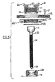
- FIG. 1 is a plane view of the aircraft frame 10 shown in Figure 1.
- FIG. 3 is an exploded view of the fastener assembly 18 of the present invention.
- Assembly 18 comprises the following five components: internally threaded grommet 20, collar member 25, retaining ring 28, spherical head stud bolt 30 and an externally threaded plug member 34.
- the fastener assembly When assembled, the fastener assembly is positioned within a prepared aperture in panel member 16, panel member 16 in turn being secured to the lug portion 26 of collar member 25 by rivet member 27.
- the component assembly procedure is as follows:
- the stud bolt 30 also comprises a threaded shaft portion 32 and probe tip portion 33.
- Grommet 20 has a threaded external portion 21, internal threaded portion 22, and spherical hollow portion 23.
- the stud bolt 30 is then inserted into grommet 20 and positioned in spherical hollow portion 23 of grommet 20.
- Plug member 34 is then threaded into the internal threaded portion of the grommet 20 until the plug seats lightly against the spherical head portion 31 of the stud bolt 30.
- the stud bolt 30 With the plug 34 lightly positioned against the head of the stud bolt 30, the stud bolt 30 is swiveled to both distribute the anti-seize compound and fully seat the stud bolt 30 within the spherical cavity formed by the grommet 20 and plug 34.
- the position of the plug is adjusted to allow the stud bolt to swivel freely with minimum drag and minimum axial clearance.
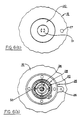
- a staking tool is then aligned with the four cut-outs 40 formed on the bottom surface of grommet 20 and four corresponding plug flanges 42 ( Figure 4) are then staked (formed) into the cutouts 46 until it makes contact therewith, thus fixing the adjustment.
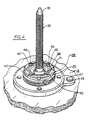
- Collar member 25 is then threaded loosely onto the external thread 21 of grommet 20 and retaining ring 28 is then installed into the retaining ring groove 39 formed in grommet 20, thus completing the assembly as shown in Figure 5.
- the assembly is then packaged and prepared for shipment to the end user.
- the recipient of the packaged fastener assembly then proceeds as follows:
- the retaining ring 28 is removed and the collar 25 is unscrewed and removed.
- the grommet/stud portion of the fastener assembly is then inserted into a prepared aperture in the panel member 16, collar member 25 then being screwed onto the grommet 20 and tightened to the desired torque with the rivet lug portion 26 against the bottom surface of panel member 16 thereby attaching panel member 16 to the grommet/bolt assembly.
- the aperture in the rivet lug portion 26 is aligned with a prepared aperture in panel member 16, rivet 27 (supplied by the user) then installed through the panel 16 and rivet lug 26 of the collar 25 to prevent rotation and loosening of collar member 25.
- the retaining ring 28 is then reinstalled into groove 39 on grommet 20 to provide back-up retention for the grommet assembly, should it loosen, thus completing the assembly for the end user.
- the spherical head portion 31 can swivel in all directions, the grommet/ball seat assembly protecting the lower surface 35 of panel member 16 from damage while head portion 31 is maintained flush with upper surface 37 of the panel member.
- the flat surface 41 of collar member 25 provides the bearing surface for panel member 16 against the mating structure thereby protecting the bearing surface of thereof from damage.
- the stud bolt 30 is rotated to unscrew it from the mating structure receptacle (not shown) on the frame of the aircraft.
- stud bolt head 31 rotates within the spherical socket created by grommet 20 and plug 34. Since head 31 is captive within the grommet/plug assembly, as the stud bolt 30 is unscrewed, the panel structure to which the assembly is attached will be lifted through the mechanical advantage provided by threads 32.
- the fastener assembly of the present invention is utilized to help position a panel for installation of other fasteners on the panel, a particularly useful feature on panels with curved or compound curved surfaces which generally exhibit fit and/or fastener hole misalignment.
Abstract
Description
Claims (7)
- A fastener assembly including a bolt having the capability of swivelling to locate and be inserted into an aperture formed in a mating structure comprising:characterized in that said internally threaded hollow portion (22) opens out through the axial end of said grommet (20) from which the threaded shaft portion (32) extends and said plug member (34) is an annular member disposed about said stud bolt (30), and that said grommet (20) and said plug member (34) have mechanical means (40, 42) for fixing the position of said plug member (34) in said grommet (20), so that said spherically shaped head (31) is held captive within said spherical cavity as the stud bolt (30) is unscrewed.an annular grommet (20) having an externally threaded portion (21), an internally threaded hollow portion (22) which opens out through one axial end of said grommet (20) and a spherical hollow portion (23) which opens out through the other, opposite axial end (38) of said grommet (20) ;a stud bolt (30) having a head (31) that is spherically shaped and a threaded shaft portion (32) ;an externally threaded plug member (34), the plug member (34) being threadably engaged with the internal threaded hollow portion (22) of said grommet (20) to form a spherical cavity for receiving the spherical head portion (31) of said stud bolt (30) and with said threaded shaft portion (37) extending out from one of said ends of the grommet (20); anda collar member (25) threadably engaged with the external threads (21) of said grommet (20);
- The fastener assembly of claim 1, characterized by further including a retaining ring (28) positioned in a groove (39) formed on the external diameter of said grommet (20).
- The fastener assembly of claim 1, characterized in that said grommet (20) is positioned in an aperture formed in a panel member (16).
- The fastener assembly of claim 3, characterized in that a fastener member (27) extends between coaligned apertures formed in said panel member (16) and said collar member (25).
- The fastener assembly of claim 1, characterized in that said threaded shaft portion (32) has a non-threaded tip portion (33) for locating in an aperture formed in a mating structure.
- The fastener assembly of claim 3, characterized in that said panel member (16) has a curved surface.
- The fastener assembly of claim 1, characterized in that said mechanical means has a plurality of cut-outs (40) formed on the bottom surface of said grommet (20) and a plurality of flange members (42) formed on said plug member (34), said flange members (42) being forced into said grommet cut-outs (40) whereby the position of said plug member (34) in said assembly is fixed.
Applications Claiming Priority (3)
| Application Number | Priority Date | Filing Date | Title |
|---|---|---|---|
| US69629896A | 1996-08-13 | 1996-08-13 | |
| US696298 | 1996-08-13 | ||
| PCT/US1997/013635 WO1998006917A1 (en) | 1996-08-13 | 1997-08-04 | Self-aligning fastener system |
Publications (3)
| Publication Number | Publication Date |
|---|---|
| EP0854965A1 EP0854965A1 (en) | 1998-07-29 |
| EP0854965A4 EP0854965A4 (en) | 1999-11-03 |
| EP0854965B1 true EP0854965B1 (en) | 2003-05-28 |
Family
ID=24796495
Family Applications (1)
| Application Number | Title | Priority Date | Filing Date |
|---|---|---|---|
| EP97936373A Expired - Lifetime EP0854965B1 (en) | 1996-08-13 | 1997-08-04 | Self-aligning fastener system |
Country Status (4)
| Country | Link |
|---|---|
| EP (1) | EP0854965B1 (en) |
| AT (1) | ATE241748T1 (en) |
| DE (1) | DE69722366D1 (en) |
| WO (1) | WO1998006917A1 (en) |
Families Citing this family (10)
| Publication number | Priority date | Publication date | Assignee | Title |
|---|---|---|---|---|
| IES20000525A2 (en) * | 2000-06-29 | 2001-08-08 | Sunarc Ltd | Mounting Bolt for Glass Panels |
| GB0905818D0 (en) | 2009-04-06 | 2009-05-20 | Airbus Uk Ltd | Coupling assembly |
| EP2941575B1 (en) | 2013-01-02 | 2018-05-16 | Illinois Tool Works Inc. | Twist-in-place grommet connection assembly |
| US9169862B2 (en) * | 2013-02-19 | 2015-10-27 | The Boeing Company | Self-aligning sleeved protruding head fasteners with electromagnetic effect protection features |
| GB201314061D0 (en) * | 2013-08-06 | 2013-09-18 | Rolls Royce Plc | Attachment device for non-permanently attaching a child component to a parent component |
| US9957989B2 (en) | 2016-05-31 | 2018-05-01 | The Boeing Company | Swivel nut assembly |
| DE202016103999U1 (en) * | 2016-07-12 | 2016-08-18 | Fairchild Fasteners Europe - Camloc Gmbh | Insert for connecting an electrical connection to a wall |
| US11448254B2 (en) | 2018-05-31 | 2022-09-20 | The Boeing Company | Retained self-aligning washer and nut assembly and method for fabrication by additive manufacturing |
| CN109578414B (en) * | 2018-12-10 | 2021-07-20 | 中国航发四川燃气涡轮研究院 | Self-adaptive axis deflection bolt and using method thereof |
| DE102018132192A1 (en) * | 2018-12-13 | 2020-06-18 | Böllhoff Verbindungstechnik GmbH | Hollow cylindrical base element of a connection unit |
Family Cites Families (11)
| Publication number | Priority date | Publication date | Assignee | Title |
|---|---|---|---|---|
| US930810A (en) * | 1909-05-07 | 1909-08-10 | William Smith | Stay-bolt. |
| FR26670E (en) * | 1922-07-17 | 1924-02-28 | Closing device particularly applicable to motor vehicle hoods | |
| US2331322A (en) * | 1941-01-23 | 1943-10-12 | Lester E Hutson | Nut anchor |
| US2900196A (en) * | 1958-01-23 | 1959-08-18 | Artie D Nienke | Eccentrically offset ball joint for front wheel stub axle suspension |
| DE2530854C3 (en) * | 1975-01-03 | 1980-01-24 | Guenter 5013 Elsdorf Busch | Device for the attachment of wooden frames and the like |
| US4971497A (en) * | 1990-03-02 | 1990-11-20 | The United States Of America As Represented By The Secretary Of The Air Force | Fastener system |
| FR2674554B1 (en) * | 1991-03-29 | 1998-08-21 | Saint Gobain Vitrage Int | SYSTEM FOR FIXING A GLASS PLATE. |
| FR2703092B1 (en) * | 1993-03-25 | 1995-06-02 | Vertal Sud Est | Device for fixing a glazing to a supporting structure. |
| DE4310002C1 (en) * | 1993-03-27 | 1994-04-21 | Kellermann Fa Rudolf | Noise discharge connecting component - has body with projection having recess in which seal sits and has friction surfaces between body and screw |
| CA2128453A1 (en) * | 1993-07-22 | 1995-01-23 | Garth B. Maughan | Ball and socket joint assembly |
| FR2713258B1 (en) * | 1993-11-30 | 1996-02-09 | Saint Gobain Vitrage | Mechanical connection between a glazed element and a supporting structure. |
-
1997
- 1997-08-04 AT AT97936373T patent/ATE241748T1/en not_active IP Right Cessation
- 1997-08-04 WO PCT/US1997/013635 patent/WO1998006917A1/en active IP Right Grant
- 1997-08-04 EP EP97936373A patent/EP0854965B1/en not_active Expired - Lifetime
- 1997-08-04 DE DE69722366T patent/DE69722366D1/en not_active Expired - Lifetime
Also Published As
| Publication number | Publication date |
|---|---|
| ATE241748T1 (en) | 2003-06-15 |
| EP0854965A1 (en) | 1998-07-29 |
| EP0854965A4 (en) | 1999-11-03 |
| DE69722366D1 (en) | 2003-07-03 |
| WO1998006917A1 (en) | 1998-02-19 |
Similar Documents
| Publication | Publication Date | Title |
|---|---|---|
| US4815908A (en) | Captive panel fastener assembly | |
| EP0854965B1 (en) | Self-aligning fastener system | |
| US5006025A (en) | Self-locking nut | |
| US5037259A (en) | Nut with sleeve lock | |
| US4735536A (en) | Captive panel fastener assembly and method for installing the same | |
| US2820499A (en) | Floating, swivelling anchor nut | |
| US5071279A (en) | Pivotal attachment means | |
| US4830557A (en) | Self-aligning floating nut fastener | |
| US4324517A (en) | Panel fastener assembly with retainer ring | |
| US4125140A (en) | Access panel fastener | |
| US5941669A (en) | Jack-out captivated screw | |
| US5125861A (en) | Lifting eyebolt assembly | |
| US3640327A (en) | Fastener with floating nut | |
| GB2196084A (en) | Captive panel fasteners | |
| US5738477A (en) | Panel snap fastener assembly | |
| JPH0293112A (en) | Captive screw assembly | |
| US5743692A (en) | Captive bolt assembly | |
| US4906153A (en) | Captive panel fastener assembly | |
| US6866456B2 (en) | Floating captivated wrenchable nut | |
| US20060216132A1 (en) | Panel fastener with spring retaining ring | |
| US2907418A (en) | High shear strength fastener | |
| US5669105A (en) | Adjustable door hinge | |
| US4266591A (en) | Locking connector | |
| US20040013495A1 (en) | Self-aligning nut plate | |
| RU2061152C1 (en) | Device for fastening members to a panel |
Legal Events
| Date | Code | Title | Description |
|---|---|---|---|
| PUAI | Public reference made under article 153(3) epc to a published international application that has entered the european phase |
Free format text: ORIGINAL CODE: 0009012 |
|
| AK | Designated contracting states |
Kind code of ref document: A1 Designated state(s): AT BE CH DE DK ES FI FR GB GR IE IT LI LU MC NL PT SE |
|
| 17P | Request for examination filed |
Effective date: 19980806 |
|
| A4 | Supplementary search report drawn up and despatched |
Effective date: 19990923 |
|
| AK | Designated contracting states |
Kind code of ref document: A4 Designated state(s): AT BE CH DE DK ES FI FR GB GR IE IT LI LU MC NL PT SE |
|
| 17Q | First examination report despatched |
Effective date: 20020208 |
|
| GRAH | Despatch of communication of intention to grant a patent |
Free format text: ORIGINAL CODE: EPIDOS IGRA |
|
| GRAH | Despatch of communication of intention to grant a patent |
Free format text: ORIGINAL CODE: EPIDOS IGRA |
|
| GRAA | (expected) grant |
Free format text: ORIGINAL CODE: 0009210 |
|
| AK | Designated contracting states |
Designated state(s): AT BE CH DE DK ES FI FR GB GR IE IT LI LU MC NL PT SE |
|
| PG25 | Lapsed in a contracting state [announced via postgrant information from national office to epo] |
Ref country code: NL Free format text: LAPSE BECAUSE OF FAILURE TO SUBMIT A TRANSLATION OF THE DESCRIPTION OR TO PAY THE FEE WITHIN THE PRESCRIBED TIME-LIMIT Effective date: 20030528 Ref country code: LI Free format text: LAPSE BECAUSE OF FAILURE TO SUBMIT A TRANSLATION OF THE DESCRIPTION OR TO PAY THE FEE WITHIN THE PRESCRIBED TIME-LIMIT Effective date: 20030528 Ref country code: IT Free format text: LAPSE BECAUSE OF FAILURE TO SUBMIT A TRANSLATION OF THE DESCRIPTION OR TO PAY THE FEE WITHIN THE PRE;WARNING: LAPSES OF ITALIAN PATENTS WITH EFFECTIVE DATE BEFORE 2007 MAY HAVE OCCURRED AT ANY TIME BEFORE 2007. THE CORRECT EFFECTIVE DATE MAY BE DIFFERENT FROM THE ONE RECORDED.SCRIBED TIME-LIMIT Effective date: 20030528 Ref country code: FR Free format text: LAPSE BECAUSE OF FAILURE TO SUBMIT A TRANSLATION OF THE DESCRIPTION OR TO PAY THE FEE WITHIN THE PRESCRIBED TIME-LIMIT Effective date: 20030528 Ref country code: FI Free format text: LAPSE BECAUSE OF FAILURE TO SUBMIT A TRANSLATION OF THE DESCRIPTION OR TO PAY THE FEE WITHIN THE PRESCRIBED TIME-LIMIT Effective date: 20030528 Ref country code: CH Free format text: LAPSE BECAUSE OF FAILURE TO SUBMIT A TRANSLATION OF THE DESCRIPTION OR TO PAY THE FEE WITHIN THE PRESCRIBED TIME-LIMIT Effective date: 20030528 Ref country code: BE Free format text: LAPSE BECAUSE OF FAILURE TO SUBMIT A TRANSLATION OF THE DESCRIPTION OR TO PAY THE FEE WITHIN THE PRESCRIBED TIME-LIMIT Effective date: 20030528 Ref country code: AT Free format text: LAPSE BECAUSE OF FAILURE TO SUBMIT A TRANSLATION OF THE DESCRIPTION OR TO PAY THE FEE WITHIN THE PRESCRIBED TIME-LIMIT Effective date: 20030528 |
|
| REG | Reference to a national code |
Ref country code: GB Ref legal event code: FG4D |
|
| REG | Reference to a national code |
Ref country code: CH Ref legal event code: EP |
|
| REG | Reference to a national code |
Ref country code: IE Ref legal event code: FG4D |
|
| REF | Corresponds to: |
Ref document number: 69722366 Country of ref document: DE Date of ref document: 20030703 Kind code of ref document: P |
|
| RAP2 | Party data changed (patent owner data changed or rights of a patent transferred) |
Owner name: HUCK PATENTS, INC. |
|
| PG25 | Lapsed in a contracting state [announced via postgrant information from national office to epo] |
Ref country code: LU Free format text: LAPSE BECAUSE OF NON-PAYMENT OF DUE FEES Effective date: 20030804 |
|
| PG25 | Lapsed in a contracting state [announced via postgrant information from national office to epo] |
Ref country code: IE Free format text: LAPSE BECAUSE OF NON-PAYMENT OF DUE FEES Effective date: 20030805 |
|
| PG25 | Lapsed in a contracting state [announced via postgrant information from national office to epo] |
Ref country code: SE Free format text: LAPSE BECAUSE OF FAILURE TO SUBMIT A TRANSLATION OF THE DESCRIPTION OR TO PAY THE FEE WITHIN THE PRESCRIBED TIME-LIMIT Effective date: 20030828 Ref country code: PT Free format text: LAPSE BECAUSE OF FAILURE TO SUBMIT A TRANSLATION OF THE DESCRIPTION OR TO PAY THE FEE WITHIN THE PRESCRIBED TIME-LIMIT Effective date: 20030828 Ref country code: GR Free format text: LAPSE BECAUSE OF FAILURE TO SUBMIT A TRANSLATION OF THE DESCRIPTION OR TO PAY THE FEE WITHIN THE PRESCRIBED TIME-LIMIT Effective date: 20030828 Ref country code: GB Free format text: LAPSE BECAUSE OF NON-PAYMENT OF DUE FEES Effective date: 20030828 Ref country code: DK Free format text: LAPSE BECAUSE OF FAILURE TO SUBMIT A TRANSLATION OF THE DESCRIPTION OR TO PAY THE FEE WITHIN THE PRESCRIBED TIME-LIMIT Effective date: 20030828 |
|
| PG25 | Lapsed in a contracting state [announced via postgrant information from national office to epo] |
Ref country code: DE Free format text: LAPSE BECAUSE OF FAILURE TO SUBMIT A TRANSLATION OF THE DESCRIPTION OR TO PAY THE FEE WITHIN THE PRESCRIBED TIME-LIMIT Effective date: 20030829 |
|
| PG25 | Lapsed in a contracting state [announced via postgrant information from national office to epo] |
Ref country code: MC Free format text: LAPSE BECAUSE OF NON-PAYMENT OF DUE FEES Effective date: 20030831 |
|
| NLT2 | Nl: modifications (of names), taken from the european patent patent bulletin |
Owner name: HUCK PATENTS, INC. |
|
| PG25 | Lapsed in a contracting state [announced via postgrant information from national office to epo] |
Ref country code: ES Free format text: LAPSE BECAUSE OF FAILURE TO SUBMIT A TRANSLATION OF THE DESCRIPTION OR TO PAY THE FEE WITHIN THE PRESCRIBED TIME-LIMIT Effective date: 20030908 |
|
| NLV1 | Nl: lapsed or annulled due to failure to fulfill the requirements of art. 29p and 29m of the patents act | ||
| REG | Reference to a national code |
Ref country code: CH Ref legal event code: PL |
|
| PLBE | No opposition filed within time limit |
Free format text: ORIGINAL CODE: 0009261 |
|
| STAA | Information on the status of an ep patent application or granted ep patent |
Free format text: STATUS: NO OPPOSITION FILED WITHIN TIME LIMIT |
|
| GBPC | Gb: european patent ceased through non-payment of renewal fee | ||
| 26N | No opposition filed |
Effective date: 20040302 |
|
| REG | Reference to a national code |
Ref country code: IE Ref legal event code: MM4A |
|
| EN | Fr: translation not filed |