EP0854797B1 - Timber bank with upper connection means - Google Patents
Timber bank with upper connection means Download PDFInfo
- Publication number
- EP0854797B1 EP0854797B1 EP96935763A EP96935763A EP0854797B1 EP 0854797 B1 EP0854797 B1 EP 0854797B1 EP 96935763 A EP96935763 A EP 96935763A EP 96935763 A EP96935763 A EP 96935763A EP 0854797 B1 EP0854797 B1 EP 0854797B1
- Authority
- EP
- European Patent Office
- Prior art keywords
- post
- upper connection
- coupling device
- connection means
- arrangement according
- Prior art date
- Legal status (The legal status is an assumption and is not a legal conclusion. Google has not performed a legal analysis and makes no representation as to the accuracy of the status listed.)
- Expired - Lifetime
Links
- 230000008878 coupling Effects 0.000 claims abstract description 30
- 238000010168 coupling process Methods 0.000 claims abstract description 30
- 238000005859 coupling reaction Methods 0.000 claims abstract description 30
- 230000000712 assembly Effects 0.000 claims abstract description 11
- 238000000429 assembly Methods 0.000 claims abstract description 11
- 238000006073 displacement reaction Methods 0.000 claims 2
- 230000000694 effects Effects 0.000 claims 1
- 239000000463 material Substances 0.000 description 5
- 238000010276 construction Methods 0.000 description 2
- 208000027418 Wounds and injury Diseases 0.000 description 1
- 230000003213 activating effect Effects 0.000 description 1
- 239000011248 coating agent Substances 0.000 description 1
- 238000000576 coating method Methods 0.000 description 1
- 230000006378 damage Effects 0.000 description 1
- 208000014674 injury Diseases 0.000 description 1
Images



Classifications
-
- B—PERFORMING OPERATIONS; TRANSPORTING
- B60—VEHICLES IN GENERAL
- B60P—VEHICLES ADAPTED FOR LOAD TRANSPORTATION OR TO TRANSPORT, TO CARRY, OR TO COMPRISE SPECIAL LOADS OR OBJECTS
- B60P3/00—Vehicles adapted to transport, to carry or to comprise special loads or objects
- B60P3/40—Vehicles adapted to transport, to carry or to comprise special loads or objects for carrying long loads, e.g. with separate wheeled load supporting elements
- B60P3/41—Vehicles adapted to transport, to carry or to comprise special loads or objects for carrying long loads, e.g. with separate wheeled load supporting elements for log transport
Definitions
- the present invention relates to a vehicle mounted timber bank comprising a horizontal load supporting beam and essentially vertical post assemblies mounted at each end of the beam, wherein each post assembly includes a bottom post anchored to the beam and at least one upper post which is displaceable telescopically in relation to the bottom post, wherein a pivotal upper connection means is pivotally mounted at the first upper post, and wherein the upper post carries a coupling device for coupling with the upper connection means when said means is positioned so as to couple the two posts together.
- the object of the present invention is to eliminate at least partially the drawbacks of earlier known arrangements of the kind defined in the introduction, and to provide an arrangement of simple construction and high operational reliability.
- the arrangement can be used both to compress loaded material and to firmly restrain the material.
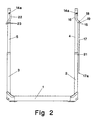
- Figures 1 and 2 illustrate a timber bank, which is intended to be mounted on goods vehicle such as to extend transversely to the long axis of the vehicle.
- the vehicle carries a plurality of such timber banks in space relationship in the longitudinal direction of the vehicle.
- the timber bank includes a horizontal beam 1, which is attached to the chassis of the vehicle, and to post assemblies each of which comprises a respective bottom post 2 and 3, and a respective top post 4 and 5, said post assemblies extending vertically upwards from respective ends of the beam 1. Additional posts may be arranged telescopically between the top and bottom posts.
- the respective bottom posts 2 and 3 and top posts 4 and 5 are of generally square cross-section and are generally identical with one another, although in mirror image.
- the bottom ends of the bottom posts 2 and 3 are anchored to the beam 1 in a conventional manner.
- the top posts 4 and 5 can be moved telescopically within the bottom posts 2 and 3, with the aid of mutually identical piston-cylinder devices.
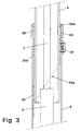
- Each piston-cylinder device includes a cylinder 6 whose bottom end is attached to respective bottom ends of the bottom posts 2 and 3, and a piston rod 7 whose upper end carries an enlargement 8 on which a gear rack 9 is mounted.
- a plate 11 is secured to the rack 9 by means of a screw joint 10. Detachably clamped between the plate 11 and the enlargement 8 is a slide rail 12 whose one side is in abutment with the rack 9 and whose other side is intended to slide against the top post 4.
- the upper end of the top post 4 is closed by a cover member 13.
- a gear wheel or pinion 14 is rotatably mounted within the top post 4 on a shaft 14a and engages with the rack 9.
- the shaft 14a of the pinion wheel 14 is connected to identical pivot arms 16 of an upper connection means 15, on opposite sides of the post assembly.
- the upper connection means 15 also comprises a rail or bar 17 which can be pivoted on the mutually connected arms 16 at 18.
- the left end of the rail 17 is provided with a rod 17a.
- the arm 16 includes a stop shoulder 19 which prevents the rail 17 from rotating anticlockwise on the arm 16 to a greater extent than that shown in Figure 4.
- the arrangement also includes slide shoulders 20 disposed on the inside of the bottom posts 2, 3 in a detachable holder 20a, said slide shoulders functioning to reduce wear and to facilitate movement of the top posts 4, 5 within the bottom posts.
- the holder 20a is comprised of a sleeve of square cross-section and includes a bevelled bottom part and a rectangular recess on two mutually opposing sides.
- the shoulders 20 may be made of a highly durable plastic material that exhibits low sliding resistance and are detachably inserted into said recesses.
- a brake means 21 which can be actuated manually to adjust the friction between the top and bottom posts.
- the brake means 21 is suitably comprised of a screw provided with a friction coating.
- Figures 5 and 6 illustrate coupling means that includes two mutually identical capture arms 22 which are connected by a shaft 25 and the ends of which are rigidly connected to a shaft and a pinion wheel identical to the shaft 14a and the pinion wheel 14 shown in Figure 4.
- the pinion wheel 14 and thus the arms 22 are actuated by means 6-12, 14 identical with those used to actuate the arms 16.
- Each arm 22 is provided with two identical recesses 23 whose right flanks 24 in Figure 5 slope upwards and to the left in said Figure when the arms are in the positions shown in Figure 5.
- Figure 7 illustrates a further embodiment that lies within the scope of the present invention and which finds correspondence in the earlier described embodiment but with the difference that the upper connection means 15 is divided into a first upper connection part 170 and a second upper connection part 171, wherein the first upper connection part 170 is pivotally attached to a first pivot arm 180 in a manner similar to that described above, and wherein the second upper connection part 171 is pivotally attached to a second pivot arm 181.
- the two parts 170, 171 of the upper connection means are intended to be hooked together centrally of the two post assemblies, namely the bottom posts 2, 3, and the top posts 4, 5 midway over the beam 1 with a similar hooking action to that described and illustrated in the previous figures.
- the first upper connection part 170 is provided with an attachment loop 190 attached to its free end.
- the loop is intended to be hooked firmly in a coupling device 220 that includes at least one recess 230 attached to the free end of the second upper connection part 171 (fig. 7 is showing two recesses), the recess 230 having upwardly sloping flank surfaces 240 in accordance with the aforedescribed.
- the location of the coupling device 220 is arranged centrally between the two top posts.
- the embodiment illustrated in Figure 7 also includes the top posts 4, 5 whose upper ends slope inwards.
- the two post assembly 2, 4 and 3, 5 When the vehicle is loaded or empty, the two post assembly 2, 4 and 3, 5 will be mutually connected by means of the upper connection means 15. In this mode of the arrangement, the rack 9 in the upper post 4 will be in the intermediate position shown in Figure 4, whereas the rack 9 in the upper post 5 will be in the position shown in Figure 5.
- the piston rod 7 in the left posts 3, 5 When activating the hydraulic system in which the two piston-cylinder devices 6, 7 are included and which is manoeuvred from the vehicle driving cabin, the piston rod 7 in the left posts 3, 5 will move upwards.
- This upward movement causes the pinion wheel 14 to be rotated clockwise in Figure 5 by the rack 9, wherewith the arms 22 are swung clockwise so that the edges 24 of the recessed portion 23 in which the rod 17a is held will extend vertically or slope upwardly to the right in Figure 5.
- the screw joint 10 strikes against the cover member 13 at the end of the pivoting movement.
- the piston rod 7 is then moved upwards in the right posts 2, 4 from the position shown in Figure 4 therewith causing the rack 9 to rotate the pinion wheel 14 clockwise.
- the upper connection means 15 is therewith swung clockwise to the position shown in Figure 2. Because the upper connection means 15 is divided, the rail 17 will hang vertically along the post assemblies 2, 4. The upper part of the joint 10 will be in abutment with the cover member 13 at the end of the pivoting movement.
- piston-cylinder devices 6, 7 in the two post assemblies are then actuated so that the piston rods move the top posts 4, 5 to their uppermost positions, shown in Figure 2, through the medium of the gear racks 9, the joints 10 and the cover members 13.
- the piston-cylinder device 6, 7 in the right post assembly 3, 5 is then actuated so as to swing the upper connection means 15 anticlockwise from the position shown in Figure 2.
- the rail 17 is not entrained by this swinging movement until the stop shoulder 19 has come into engagement with the rail.
- the rail 17 has passed its vertical position, it falls anticlockwise in across the load until stopped by the stop shoulder 19.
- the piston-cylinder devices in both post assemblies are actuated so that said post assemblies and the upper connection means 15 will be lowered.
- the capture arms 22 are swung slightly in an anticlockwise direction as a result of pressing against the upper side of the load. This ensures that the rod 17a will not release its engagement with the recess 23.
- the load is now firmly clamped and a cabin mounted pressure monitor will indicate when it is necessary to subsequently further clamp the load during its transportation. If this becomes necessary, the piston-cylinder devices 6, 7 are actuated so as to cause the upper connection means 15 to be moved to a lower position.
- the capture arms 22 When unloading the vehicle, the capture arms 22 are slightly swung in a clockwise direction away from the position shown in Figures 1 and 5, in the aforedescribed manner, so as to enable the upper connection means 15 to be swung clockwise out of engagement with the recesses 23 in the capture arms to the position shown in Figure 2.
- the capture arms are also swung to this position.
Landscapes
- Engineering & Computer Science (AREA)
- Health & Medical Sciences (AREA)
- Public Health (AREA)
- Transportation (AREA)
- Mechanical Engineering (AREA)
- Forklifts And Lifting Vehicles (AREA)
- Fittings On The Vehicle Exterior For Carrying Loads, And Devices For Holding Or Mounting Articles (AREA)
- Conveying And Assembling Of Building Elements In Situ (AREA)
- Pit Excavations, Shoring, Fill Or Stabilisation Of Slopes (AREA)
- Road Paving Structures (AREA)
- Connection Of Plates (AREA)
- Pharmaceuticals Containing Other Organic And Inorganic Compounds (AREA)
- Chemical And Physical Treatments For Wood And The Like (AREA)
- Rod-Shaped Construction Members (AREA)
- Prostheses (AREA)
Abstract
Description
Claims (19)
- A vehicle timber bank arrangement comprising a horizontal load supporting beam (1) and generally vertical post assemblies (2, 4 and 3, 5) attached at respective ends of said beam, wherein each of the post assemblies includes a bottom post (2, 3) anchored to said beam, and at least one top post (4, 5) which is telescopically displaceable relative to said bottom post, wherein a pivotal upper connection means (15) is pivotally mounted at the first top post (4), wherein a device (22) for coupling with the upper connection means is mounted at the second top post (5) when said upper connection means is in a position in which it connects said two top posts, and wherein the upper connection means is swung by a piston-cylinder device (6, 7) which functions to displace the first top post telescopically in relation to the first bottom post, characterized in that the first top post (4) and that part (7) of the piston-cylinder device (6, 7) which actuates said first top post are coupled together with the aid of a rack-and-pinion arrangement (9-12, 14).
- An arrangement according to Claim 1, characterized in that the coupling device (22) is pivotally journalled on the second top post (5) by means of a piston-cylinder device (6, 7) which functions to displace the second top post telescopically in relation to the second bottom post; and in that the second top post and that part (7) of the piston-cylinder device which actuates said second top post are coupled with the aid of a rack-and-pinion arrangement (9-12, 14).
- An arrangement according to Claim 1 or 2, characterized in that the rack-and-pinion arrangement (9-12, 14) includes at least one gear rack (9) mounted on the actuated part (7) of the piston-cylinder device (6, 7) and engaging with at least one pinion wheel (14) rotatably connected to the upper connection means (15) and to the coupling device (22) respectively.
- An arrangement according to Claim 3, characterized by a slide element (12) mounted between the gear rack (9) and the inner surface of the top post (4, 5).
- An arrangement according to any one of the preceding claims, characterized in that pivotal movement of the coupling device (22) is effected by a piston-cylinder device (6, 7) which functions to displace the second top post (5) telescopically in relation to the second bottom post (3).
- An arrangement according to any one of the preceding claims, characterized by a brake means (21), which preferably has a controllable brake action, mounted between the top post (4, 5) and the bottom post (2, 3) and functioning to prevent relative displacement of said top and bottom posts until the pivotal movements of the upper connection means (15) and the coupling device (22) have terminated.
- An arrangement according to any one of the preceding claims, characterized in that the upper connection means (15) includes a first part (16) which is pivotally connected to the top post (4) and also connected pivotally to a second part (17) which engages the coupling device (22) and which is longer than said first part, such as to restrict relative movement relative said first part.
- An arrangement according to any one of the preceding claims, characterized in that the coupling device (22) includes at least one recess (23) which prevents the upper connection means (15) from swinging away from and out of engagement with the coupling device when said coupling device is in a first position and permits the upper connection means to swing away from and out of engagement with said coupling device when said coupling device is in a second position.
- An arrangement according to any one of the preceding claims, characterized by a sleeve (20a) provided with slide element (20) mounted, preferably detachably, between respective bottom posts (2 and 3) and respective top posts (4 and 5).
- An arrangement according to Claim 1, characterized in that the upper connection means (15) includes a first upper connection part (170) which is mounted for pivotal movement at the first top post (4), and a second upper connection part (171) which is pivotally mounted at the second top post (5) and which carries a device (220) for coupling to the first connection part (170) when the upper connection means (15) is in a position in which it binds the two top posts together.
- An arrangement according to Claim 10, characterized in that the coupling device (220) is fixedly mounted on the second upper connection part (171) which, in turn, is pivotally mounted on the second top post (5) by means of a piston-cylinder device (6, 7) which functions to displace the second top post telescopically in relation to the second bottom post; and in that the second top post and that part (7) of the piston-cylinder device which actuates said second top post are mutually coupled with the aid of a rack-and-pinion arrangement (9-12, 14).
- An arrangement according to Claim 10 or 11, characterized in that the rack-and-pinion arrangement (9-12, 14) includes at least one gear rack (9) mounted on the actuated part (7) of the piston-cylinder device (6, 7) and engaging with at least one pinion (14) that is rotatably connected to the upper connection means (15) and the coupling device (220) respectively.
- An arrangement according to Claim 12, characterized by a slide element (12) which is mounted between the rack (9) and the inner surface of the top post (4, 5).
- An arrangement according to any one of Claims 10-13, characterized in that the coupling device (220) is swung by a piston-cylinder device (6, 7) which functions to displace the second top post (5) telescopically in relation to the second bottom post (3).
- An arrangement according to any one of Claims 10-14, characterized by brake means (21), which preferably have a controllable braking effect, mounted between the top posts (4, 5) and respective bottom posts (2, 3), said brake means functioning to prevent relative displacement of the top and bottom posts until pivotal movement of the upper connection means (15) and the coupling device (220) has terminated.
- An arrangement according to any one of Claims 10-15, characterized in that the upper connection means (15) includes a first part (180) which is pivotally connected to the top post (4) and also pivotally connected to the first upper connection part (170) which engages the coupling device (220) relative to the first part (180), such as to restrict pivotal movement relative to the first part (180).
- An arrangement according to any one of Claims 10-16, characterized in that the upper connection means (15) includes a second part (181) which is pivotally connected at the top post (5) and which is also pivotally connected to the second upper connection part (171) connected to the coupling device (220), such as to limit pivotal movement relative to said second part (181).
- An arrangement according to any one of Claims 10-17, characterized in that the coupling device (220) includes at least one recess (230) which functions to prevent the upper connection means (15) swinging away from and out of engagement with the coupling device when said coupling device is in a first position and permits the upper connection means to swing away from and out of engagement with the coupling device when said coupling device is in a second position.
- An arrangement according to any one of Claims 10-18, characterized by a sleeve (20a) provided with a slide element (20) and mounted, preferably detachably, between respective bottom posts (2, 3) and top posts (4, 5).
Applications Claiming Priority (3)
| Application Number | Priority Date | Filing Date | Title |
|---|---|---|---|
| SE9503780A SE505110C3 (en) | 1995-10-26 | 1995-10-26 | Load bank with overhead |
| SE9503780 | 1995-10-26 | ||
| PCT/SE1996/001379 WO1997015470A1 (en) | 1995-10-26 | 1996-10-28 | Timber bank with upper connection means |
Publications (2)
| Publication Number | Publication Date |
|---|---|
| EP0854797A1 EP0854797A1 (en) | 1998-07-29 |
| EP0854797B1 true EP0854797B1 (en) | 2001-09-26 |
Family
ID=20399980
Family Applications (1)
| Application Number | Title | Priority Date | Filing Date |
|---|---|---|---|
| EP96935763A Expired - Lifetime EP0854797B1 (en) | 1995-10-26 | 1996-10-28 | Timber bank with upper connection means |
Country Status (9)
| Country | Link |
|---|---|
| US (1) | US5964557A (en) |
| EP (1) | EP0854797B1 (en) |
| JP (1) | JPH11513637A (en) |
| AT (1) | ATE206094T1 (en) |
| CA (1) | CA2234169A1 (en) |
| DE (1) | DE69615573T2 (en) |
| NO (1) | NO310859B1 (en) |
| SE (1) | SE505110C3 (en) |
| WO (1) | WO1997015470A1 (en) |
Families Citing this family (15)
| Publication number | Priority date | Publication date | Assignee | Title |
|---|---|---|---|---|
| SE508867C2 (en) * | 1997-03-03 | 1998-11-09 | Exte Fab | Mounting device for a load bank |
| GB9901474D0 (en) * | 1999-01-23 | 1999-03-17 | Ross Ralph B | Cargo handling apparatus |
| US6182837B1 (en) | 2000-01-12 | 2001-02-06 | Cargomax | Method and apparatus for secure storage and handling of elongate objects |
| GB2361909C (en) * | 1999-01-23 | 2012-11-14 | Michael Wayne Crabtree | Method and apparatus for secure storage and handling of elongate objects |
| DE29906754U1 (en) | 1999-04-16 | 1999-07-08 | Erbslöh AG, 42553 Velbert | Frame for forming a stackable storage and transport device for elongated objects |
| US6468008B2 (en) * | 1999-09-30 | 2002-10-22 | Great Lakes Manufacturing, Inc. | Apparatus for constraining the position of logs on a truck or trailer |
| US6149360A (en) * | 1999-10-07 | 2000-11-21 | Billotte; Keith W. | Vehicle with trussed box beam load supports |
| GB0017969D0 (en) | 2000-07-22 | 2000-09-13 | Ross Ralph B | Cargo handling apparatus |
| US6499922B2 (en) * | 2001-04-11 | 2002-12-31 | Terry Coray | Log divider |
| CA2534161A1 (en) * | 2006-01-16 | 2007-07-16 | Marcel Couture | Load transport device |
| SE533350C2 (en) * | 2009-01-22 | 2010-08-31 | Ssab Oxeloesund Ab | Stake body |
| US8322957B1 (en) * | 2011-06-06 | 2012-12-04 | Anthony Pennisi | Chuck and lock system with extendable brace for preventing falling of flatbed truck loads |
| CN102673577B (en) * | 2012-05-24 | 2015-05-13 | 南车石家庄车辆有限公司 | Multifunctional railway transportation truck |
| US10144336B1 (en) * | 2015-07-24 | 2018-12-04 | Coilkeeper, LLC | Systems and methods for securing cargo on a flatbed carrier |
| US20260043263A1 (en) * | 2024-08-08 | 2026-02-12 | Clayton Joseph WITTER | Utility pole lifting mechanism with safety sling |
Family Cites Families (16)
| Publication number | Priority date | Publication date | Assignee | Title |
|---|---|---|---|---|
| US858834A (en) * | 1907-01-29 | 1907-07-02 | Livin Stas | Car-stake. |
| US870123A (en) * | 1907-03-01 | 1907-11-05 | Jere D Perry | Car-stake. |
| US893165A (en) * | 1907-09-03 | 1908-07-14 | Samuel Haley | Car-stake. |
| US1221405A (en) * | 1915-11-29 | 1917-04-03 | Allis Chalmers Mfg Co | Locking device. |
| US1342654A (en) * | 1919-07-16 | 1920-06-08 | Carl O Torgerson | Stake-holder |
| US2754769A (en) * | 1952-06-30 | 1956-07-17 | Yorston James Keith | Bunk stakes for use on logging trucks, railway flat cars and the like |
| US3637235A (en) * | 1969-10-13 | 1972-01-25 | Ostbergs Fabriks Ab | Load carrier of clamping type for trees and logs |
| SE417182B (en) * | 1979-01-25 | 1981-03-02 | Einar Karlsson | Arrangement for compression of unpruned timber |
| SE420699B (en) * | 1979-08-20 | 1981-10-26 | Exte Fab | Arrangement related to load-carrying members for compressing material, preferably trees or parts thereof |
| SE426677B (en) * | 1981-03-31 | 1983-02-07 | Exte Fab | Arrangement for a loading bar for compacting of material |
| US4375893A (en) * | 1981-08-10 | 1983-03-08 | Curtis Arney L | Extendible bunk stake |
| SU1186539A1 (en) * | 1984-04-12 | 1985-10-23 | Vnii Vagonostroenia | Arrangement for securing long cargoes on vehicle |
| FI76965C (en) * | 1984-07-03 | 1989-01-10 | Interwood Oy | Side restriction post for cargo space. |
| FI84243C (en) * | 1986-11-26 | 1991-11-11 | Rkp Rovaniemen Konepaja Ky Tim | Device for compression and clamping of unquestioned wood |
| SU1576379A1 (en) * | 1988-09-20 | 1990-07-07 | Центральный Научно-Исследовательский И Проектно-Конструкторский Институт Механизации И Энергетики Лесной Промышленности | Vehicle for carrying trees |
| US5567096A (en) * | 1994-09-13 | 1996-10-22 | Howard; Douglas D. | Shear-pin system for logging truck bunk |
-
1995
- 1995-10-26 SE SE9503780A patent/SE505110C3/en not_active IP Right Cessation
-
1996
- 1996-10-28 US US09/051,035 patent/US5964557A/en not_active Expired - Lifetime
- 1996-10-28 AT AT96935763T patent/ATE206094T1/en active
- 1996-10-28 EP EP96935763A patent/EP0854797B1/en not_active Expired - Lifetime
- 1996-10-28 JP JP9516550A patent/JPH11513637A/en active Pending
- 1996-10-28 CA CA002234169A patent/CA2234169A1/en not_active Abandoned
- 1996-10-28 DE DE69615573T patent/DE69615573T2/en not_active Expired - Lifetime
- 1996-10-28 WO PCT/SE1996/001379 patent/WO1997015470A1/en not_active Ceased
-
1998
- 1998-04-23 NO NO19981824A patent/NO310859B1/en not_active IP Right Cessation
Also Published As
| Publication number | Publication date |
|---|---|
| SE505110C2 (en) | 1997-06-30 |
| WO1997015470A1 (en) | 1997-05-01 |
| DE69615573T2 (en) | 2002-09-05 |
| SE9503780L (en) | 1997-04-27 |
| SE505110C3 (en) | 1997-12-22 |
| JPH11513637A (en) | 1999-11-24 |
| CA2234169A1 (en) | 1997-05-01 |
| NO981824D0 (en) | 1998-04-23 |
| SE9503780D0 (en) | 1995-10-26 |
| DE69615573D1 (en) | 2001-10-31 |
| NO310859B1 (en) | 2001-09-10 |
| ATE206094T1 (en) | 2001-10-15 |
| US5964557A (en) | 1999-10-12 |
| NO981824L (en) | 1998-04-23 |
| EP0854797A1 (en) | 1998-07-29 |
Similar Documents
| Publication | Publication Date | Title |
|---|---|---|
| US5964557A (en) | Timber bank with upper connection mechanism | |
| CN103832310B (en) | Wheel supporting mounting assembly | |
| US4305694A (en) | Hydraulic tailgate extension, bumper and lock | |
| US4983092A (en) | Retractable arm/loader assembly | |
| US4948326A (en) | Load lifting attachment mounted on a truck frame | |
| US4325666A (en) | Materials handling device | |
| DE69431516T2 (en) | VEHICLE WITH A U-SHAPED FRAME | |
| US5678978A (en) | Apparatus for a tiltable rolloff trailer having a displacable frame | |
| US6435806B1 (en) | Pick-up vehicle having a swivel device, swivel device, and process for loading and unloading the pick-up vehicle | |
| CA2070786A1 (en) | Trailer with combined towing and centering means | |
| CA2092164A1 (en) | Hinged bows used to support tarpaulin on trailers | |
| DE69212491T2 (en) | CONSTRUCTION MACHINE WITH SWIVELING BOOM | |
| EP0235824B1 (en) | Refuse receptacle | |
| EP0805067B1 (en) | Loading lift for the container of a truck | |
| US4992014A (en) | Transport safety for containers, notably interchangeable containers | |
| SU1586936A2 (en) | Dump truck device for loading farm machines | |
| US4558879A (en) | Trailer for a truck | |
| US4378192A (en) | Vehicular lift mechanism for transporting large structural members | |
| EP0394548A2 (en) | Road trailer for container transport | |
| DE3905994C2 (en) | Front-mounted device with two gripper arms for holding cylindrical bodies in a horizontal or vertical position with hydraulic drive and with a circuit for controlling the same | |
| FI85250C (en) | KOPPEL FOER LINJEKOERNING. | |
| EP0152159A1 (en) | Improvements in or relating to load carrying vehicles | |
| NL1017096C2 (en) | Skip displacement device for loading and unloading skips on lorries, has coupling mechanism with two hooks connecting tipper frame to set down frame | |
| SU1572863A1 (en) | Road train for carrying elongated cargoes | |
| RU803U1 (en) | Device for securing cargo on the carrier |
Legal Events
| Date | Code | Title | Description |
|---|---|---|---|
| PUAI | Public reference made under article 153(3) epc to a published international application that has entered the european phase |
Free format text: ORIGINAL CODE: 0009012 |
|
| 17P | Request for examination filed |
Effective date: 19980526 |
|
| AK | Designated contracting states |
Kind code of ref document: A1 Designated state(s): AT CH DE FI FR IT LI |
|
| 17Q | First examination report despatched |
Effective date: 19991008 |
|
| GRAG | Despatch of communication of intention to grant |
Free format text: ORIGINAL CODE: EPIDOS AGRA |
|
| GRAG | Despatch of communication of intention to grant |
Free format text: ORIGINAL CODE: EPIDOS AGRA |
|
| GRAH | Despatch of communication of intention to grant a patent |
Free format text: ORIGINAL CODE: EPIDOS IGRA |
|
| GRAH | Despatch of communication of intention to grant a patent |
Free format text: ORIGINAL CODE: EPIDOS IGRA |
|
| GRAA | (expected) grant |
Free format text: ORIGINAL CODE: 0009210 |
|
| AK | Designated contracting states |
Kind code of ref document: B1 Designated state(s): AT CH DE FI FR IT LI |
|
| REF | Corresponds to: |
Ref document number: 206094 Country of ref document: AT Date of ref document: 20011015 Kind code of ref document: T |
|
| REG | Reference to a national code |
Ref country code: CH Ref legal event code: EP |
|
| REF | Corresponds to: |
Ref document number: 69615573 Country of ref document: DE Date of ref document: 20011031 |
|
| REG | Reference to a national code |
Ref country code: CH Ref legal event code: NV Representative=s name: DIPL.-ING. ETH H. R. WERFFELI PATENTANWALT |
|
| ET | Fr: translation filed | ||
| PLBE | No opposition filed within time limit |
Free format text: ORIGINAL CODE: 0009261 |
|
| STAA | Information on the status of an ep patent application or granted ep patent |
Free format text: STATUS: NO OPPOSITION FILED WITHIN TIME LIMIT |
|
| 26N | No opposition filed | ||
| REG | Reference to a national code |
Ref country code: FR Ref legal event code: PLFP Year of fee payment: 20 |
|
| PGFP | Annual fee paid to national office [announced via postgrant information from national office to epo] |
Ref country code: IT Payment date: 20151019 Year of fee payment: 20 Ref country code: DE Payment date: 20151026 Year of fee payment: 20 Ref country code: FI Payment date: 20151019 Year of fee payment: 20 Ref country code: CH Payment date: 20151012 Year of fee payment: 20 |
|
| PGFP | Annual fee paid to national office [announced via postgrant information from national office to epo] |
Ref country code: AT Payment date: 20151013 Year of fee payment: 20 Ref country code: FR Payment date: 20151102 Year of fee payment: 20 |
|
| REG | Reference to a national code |
Ref country code: DE Ref legal event code: R071 Ref document number: 69615573 Country of ref document: DE |
|
| REG | Reference to a national code |
Ref country code: CH Ref legal event code: PL |
|
| REG | Reference to a national code |
Ref country code: AT Ref legal event code: MK07 Ref document number: 206094 Country of ref document: AT Kind code of ref document: T Effective date: 20161028 |