EP0854556A2 - Charger and charging method for non-aqueous electrolyte secondary batteries - Google Patents
Charger and charging method for non-aqueous electrolyte secondary batteries Download PDFInfo
- Publication number
- EP0854556A2 EP0854556A2 EP97122093A EP97122093A EP0854556A2 EP 0854556 A2 EP0854556 A2 EP 0854556A2 EP 97122093 A EP97122093 A EP 97122093A EP 97122093 A EP97122093 A EP 97122093A EP 0854556 A2 EP0854556 A2 EP 0854556A2
- Authority
- EP
- European Patent Office
- Prior art keywords
- secondary battery
- constant voltage
- charging
- circuit
- constant
- Prior art date
- Legal status (The legal status is an assumption and is not a legal conclusion. Google has not performed a legal analysis and makes no representation as to the accuracy of the status listed.)
- Withdrawn
Links
Images
Classifications
-
- H—ELECTRICITY
- H02—GENERATION; CONVERSION OR DISTRIBUTION OF ELECTRIC POWER
- H02J—ELECTRIC POWER NETWORKS; CIRCUIT ARRANGEMENTS OR SYSTEMS FOR SUPPLYING OR DISTRIBUTING ELECTRIC POWER; SYSTEMS FOR STORING ELECTRIC ENERGY
- H02J7/00—Circuit arrangements for charging or discharging batteries or for supplying loads from batteries
- H02J7/90—Regulation of charging or discharging current or voltage
- H02J7/933—Regulation of charging or discharging current or voltage the cycle being controlled or terminated in response to electric parameters
-
- H—ELECTRICITY
- H02—GENERATION; CONVERSION OR DISTRIBUTION OF ELECTRIC POWER
- H02J—ELECTRIC POWER NETWORKS; CIRCUIT ARRANGEMENTS OR SYSTEMS FOR SUPPLYING OR DISTRIBUTING ELECTRIC POWER; SYSTEMS FOR STORING ELECTRIC ENERGY
- H02J7/00—Circuit arrangements for charging or discharging batteries or for supplying loads from batteries
-
- H—ELECTRICITY
- H01—ELECTRIC ELEMENTS
- H01M—PROCESSES OR MEANS, e.g. BATTERIES, FOR THE DIRECT CONVERSION OF CHEMICAL ENERGY INTO ELECTRICAL ENERGY
- H01M10/00—Secondary cells; Manufacture thereof
- H01M10/42—Methods or arrangements for servicing or maintenance of secondary cells or secondary half-cells
- H01M10/44—Methods for charging or discharging
-
- H—ELECTRICITY
- H02—GENERATION; CONVERSION OR DISTRIBUTION OF ELECTRIC POWER
- H02J—ELECTRIC POWER NETWORKS; CIRCUIT ARRANGEMENTS OR SYSTEMS FOR SUPPLYING OR DISTRIBUTING ELECTRIC POWER; SYSTEMS FOR STORING ELECTRIC ENERGY
- H02J7/00—Circuit arrangements for charging or discharging batteries or for supplying loads from batteries
- H02J7/50—Circuit arrangements for charging or discharging batteries or for supplying loads from batteries acting upon multiple batteries simultaneously or sequentially
-
- H—ELECTRICITY
- H02—GENERATION; CONVERSION OR DISTRIBUTION OF ELECTRIC POWER
- H02J—ELECTRIC POWER NETWORKS; CIRCUIT ARRANGEMENTS OR SYSTEMS FOR SUPPLYING OR DISTRIBUTING ELECTRIC POWER; SYSTEMS FOR STORING ELECTRIC ENERGY
- H02J7/00—Circuit arrangements for charging or discharging batteries or for supplying loads from batteries
- H02J7/60—Circuit arrangements for charging or discharging batteries or for supplying loads from batteries including safety or protection arrangements
-
- Y—GENERAL TAGGING OF NEW TECHNOLOGICAL DEVELOPMENTS; GENERAL TAGGING OF CROSS-SECTIONAL TECHNOLOGIES SPANNING OVER SEVERAL SECTIONS OF THE IPC; TECHNICAL SUBJECTS COVERED BY FORMER USPC CROSS-REFERENCE ART COLLECTIONS [XRACs] AND DIGESTS
- Y02—TECHNOLOGIES OR APPLICATIONS FOR MITIGATION OR ADAPTATION AGAINST CLIMATE CHANGE
- Y02E—REDUCTION OF GREENHOUSE GAS [GHG] EMISSIONS, RELATED TO ENERGY GENERATION, TRANSMISSION OR DISTRIBUTION
- Y02E60/00—Enabling technologies; Technologies with a potential or indirect contribution to GHG emissions mitigation
- Y02E60/10—Energy storage using batteries
Definitions
- the present invention relates to a charger and a charging method for nonaqueous electrolyte secondary batteries such as a lithium secondary battery and a lithium ion secondary battery.
- nonaqueous electrolyte secondary batteries such as a lithium secondary battery and a lithium ion secondary battery can not react on a counter electrode an oxygen gas produced therein in a fully charged state (a sate charged up to rated voltage) and return it into water unlike aqueous batteries represented by a nickel-cadmium battery and a nickel-hydrogen battery.
- nonaqueous electrolyte secondary batteries it is necessary to provide an upper limit to a charged voltage to prevent a gas from being produced in the batteries by decomposition of a nonaqueous electrolyte and to make the electrodes stably operated in order to avoid the danger of a degradation in a battery performance and battery explosion, in addition to the need for usual constant current charging.
- Nonaqueous electrolyte secondary batteries having a relatively greater capacity have been used as a power source for mobile communication instruments such as cellular phones and notebook-size personal computers.
- a charging method wherein both charging in a constant current region with a current kept constant and charging in a constant voltage region with a voltage kept constant are carried out, and wherein the magnitude of the charging current in the constant voltage region is detected, and charging is stopped when the detected current reaches a predetermined set current value (e.g. JP-A-5111184).
- the charging method having the constant current charging and the constant voltage charging, it is possible to stably and safely charge lithium ion secondary batteries even if the batteries are connected in series to obtain a relatively greater capacity.
- the charging method requires improvement in cost because many semiconductors, several external parts to be fitted and a specialized integrated circuit are needed.
- the present invention is provided to meet with such requirement. It is an object of the present invention to provide a charger and a charging method for nonaqueous electrolyte secondary batteries, which are capable of stably and safely charging a nonaqueous electrolyte secondary battery at a low cost without degrading the battery performance.
- the present invention is characterized in that there are provided a d.c. charging power supply, a constant current circuit connected to a positive side of the charging power supply through a reverse current blocking diode for preventing a reverse current to the power supply, and a constant voltage circuit connected between the constant current circuit and a negative side of the charging power supply; a nonaqueous electrolyte secondary battery to be charged is connected in parallel with the constant voltage circuit; the secondary battery is charged at a constant current by the constant current circuit until a charged voltage of the secondary battery reaches a constant voltage value determined by the constant voltage circuit; and the secondary battery is charged at a constant voltage by the constant voltage circuit when the charged voltage of the secondary battery becomes not less than the constant voltage value.
- the constant current circuit is constituted by a series connection of a field effect transistor and a resistor and that the constant voltage circuit is constituted by a Zener diode, reducing the total cost.
- the same number of Zener diodes are provided in the constant voltage circuit, and the respective Zener diodes are parallelly assigned to the respective secondary batteries.
- the upper limit for charging the respective secondary batteries can be independently determined to establish equal application of voltage.
- Zener diodes Although variations in the characteristics of Zener diodes generally causes make the breakdown voltage variable depending on a change in the magnitude in the current flowing therethrough, the present invention can operate a Zener diode at a constant current by the constant current circuit to retrain the variations due to the characteristics.
- additional reverse current blocking diodes are respectively connected between the Zener diode and the secondary battery, and between a junction of the secondary battery to the constant voltage circuit and a load side of the secondary battery.
- additional reverse current blocking diodes schottky diodes having a small forward voltage are appropriate.
- the constant voltage circuit is not activated, and the secondary battery is exclusively charged at a constant current determined by the constant current circuit in a case wherein the remaining voltage of the secondary battery is not higher than the breakdown voltage of the Zener diode at the time of starting charging.
- the charged voltage of the secondary battery is raised as the charging progresses.
- the charging current is divided into a flow through the Zener diode and a flow through the secondary battery, keeping the charged voltage of the secondary battery constant and carrying out charging at a constant voltage.
- the current flowing through the secondary battery is gradually decreased, and is finally reduced to a current value which compensates for the self-discharging of the secondary battery.
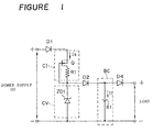
- FIG. 1 there is shown a first embodiment according to the present invention, wherein a single nonaqueous electrolyte secondary battery, e.g. a lithium ion secondary battery B1 is charged.
- the charger according to the first embodiment includes a d.c. charging power supply E, which has a positive side connected to a constant current circuit CI through a first reverse current blocking diode D1.
- a constant voltage circuit CV is connected between the constant current circuit CI and a negative side of the charging power supply E.
- the constant current circuit CI is constituted by a field effect transistor Q and a resistor R1.
- the constant voltage circuit CV is constituted by a Zener diode.
- the single secondary battery B1 is charged, and accordingly the single Zener diode ZD1 is provided in the constant voltage circuit CV.
- a battery loading portion BC is connected to the constant voltage circuit CV so that the secondary battery B1 to be charged is connected in parallel with the constant voltage circuit CV.
- a second reverse current blocking diode D2 is arranged between the constant voltage circuit CV and the battery loading portion BC to block a reverse current directed to the side of the constant voltage circuit CV.
- a third reverse current blocking diode D4 is arranged between the battery loading portion BC and a load (appliance) side of the secondary battery B1 to block a reverse current from the load side.
- the charging power supply E has an output voltage set to be higher than the breakdown voltage VZ of the Zener diode ZD1 forming the constant voltage circuit CV.
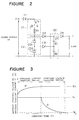
- FIG 2 there is shown a second embodiment wherein two secondary batteries are charged.
- the two secondary batteries B1 and B2 are loaded in the battery loading portion BC so that the batteries are connected in series. Accordingly, two Zener diodes ZD1 and ZD2 connected in series are provided in the constant voltage circuit CV.
- the charging power supply E has an output voltage set to be 2 times higher than the breakdown voltage VZ of each of the Zener diode ZD1 and Zd2 since the two Zener diodes are connected in series.
- the Zener diodes and the reverse current blocking diodes therefore are added according to an increase in the number of the secondary batteries to be charged though the second embodiment is similar to the first embodiment in terms of its basic structure.
- the operation of the charger according to the second embodiment will be explained in reference to the characteristic diagram about the relationship of a charging voltage and a charging current with respect to a charging time shown in Figure 3.
- the remaining voltage of the secondary batteries B1 and B2 is a low voltage near to a discharged state, and that a charging current I1 is supplied to the secondary batteries B1 and B2, the charged voltage E1 of each of the secondary battery is not higher than the breakdown voltage VZ of the Zener diodes ZD1 and ZD2 in an initial charging region.
- the charging current I1 is limited to a constant current value Is by the constant current circuit CI though the charging current has the tendency to become greater.
- the respective secondary batteries B1 and B2 are charged at a constant current having the constant current value Is in the initial charging region.
- the current value Is is preferable to be set to have substantially a value between 0.05 - 1.0 CA though the value varies on the kinds of secondary batteries to be charged.
- the charged voltages of the secondary batteries are raised by continuing charging.
- the charged voltages approach near to the breakdown voltages VZ of the Zener diodes ZD1 and ZD2
- currents gradually start to flow in the Zener diodes ZD1 and ZD2
- the charging current I1 which flows through the respective secondary batteries B1 and B2 is gradually decreased.
- the charged voltages of the secondary batteries reach the breakdown voltage VZ, almost no current flows through the secondary batteries B1 and B2.
- the voltages applied to the respective secondary batteries B1 and B2 are limited to a constant charging voltage Es by the Zener diodes ZD1 and ZD2 in a last charging region.
- the constant current circuit CI is not limited to a combination of the field effect transistor Q and the resistor R1.
- the charger and the charging method of the present invention it is not necessary to combine expensive parts such as an operational amplifier in a complicated arrangement unlike the prior art in order to charge a aqueous electrolyte secondary battery at a constant voltage after having charged it at a constant current.
- the charger is constituted by inexpensive parts as a whole. The charger can charge a nonaqueous electrolyte secondary battery in a stable and safe way without degrading performance though the charger can be prepared at a low cost.
Landscapes
- Engineering & Computer Science (AREA)
- Power Engineering (AREA)
- Manufacturing & Machinery (AREA)
- Chemical & Material Sciences (AREA)
- Chemical Kinetics & Catalysis (AREA)
- Electrochemistry (AREA)
- General Chemical & Material Sciences (AREA)
- Charge And Discharge Circuits For Batteries Or The Like (AREA)
- Secondary Cells (AREA)
Abstract
Description
Claims (10)
- A charger for a nonaqueous electrolyte secondary battery, comprising:a d.c. charging power supply;a constant current circuit connected to a positive side of the charging power supply through a reverse current blocking diode; anda constant voltage circuit including a Zener diode connected between the constant current circuit and a negative side of the charging power supply;
wherein a nonaqueous electrolyte secondary battery to be charged is connected in parallel with the constant voltage circuit, the secondary battery is charged at a constant current by the constant current circuit until a charged voltage of the secondary battery reaches a constant voltage value determined by the constant voltage circuit, and the secondary battery is charged at a constant voltage by the constant voltage circuit when the charged voltage of the secondary battery becomes not less than the constant voltage value. - A charger for a nonaqueous electrolyte secondary battery according to Claim 1, wherein the constant current circuit comprises a series circuit of a field effect transistor and a resistor.
- A charger for a nonaqueous electrolyte secondary battery according to Claim 1 or 2, wherein when a plurality of nonaqueous electrolyte secondary batteries to be charged are connected in series and the series connection of the secondary batteries is connected in parallel with the constant voltage circuit, the constant voltage circuit includes the same number of Zener diodes, and the respective Zener diodes are parallelly assigned to the respective secondary batteries.
- A charger for a nonaqueous electrolyte secondary battery according to any one of Claims 1 to 3, wherein a second reverse current blocking diode is connected between the Zener diode and the secondary battery to prevent a current from flowing in a direction opposite to a charging direction.
- A charger for a nonaqueous electrolyte secondary battery according to any one of Claims 1 to 4, wherein a third reverse current blocking diode is connected between a junction of the secondary battery to the constant voltage circuit and a load side of the secondary battery to prevent a reverse current from the load side.
- A method for charging a nonaqueous electrolyte secondary battery, wherein there are provided a d.c. charging power supply, a constant current circuit connected to a positive side of the charging power supply through a reverse current blocking diode, and a constant voltage circuit connected between the constant current circuit and a negative side of the charging power supply; and wherein a nonaqueous electrolyte secondary battery is connected in parallel with the constant voltage circuit; comprising:charging the secondary battery at a constant current by the constant current circuit until a charged voltage of the secondary battery reaches a constant voltage value determined by the constant voltage circuit; andcharging the secondary battery at a constant voltage by the constant voltage circuit when the charged voltage of the secondary battery becomes not less than the constant voltage value.
- A method for charging a nonaqueous electrolyte secondary battery according to Claim 6, wherein the constant voltage circuit comprises a Zener diode, and the constant voltage value is determined by a breakdown voltage of the Zener diode.
- A method for charging a nonaqueous electrolyte secondary battery according to Claim 6 or 7, wherein the constant current circuit comprises a series circuit of a field effect transistor and a resistor.
- A method for charging a nonaqueous electrolyte secondary battery according to any one of Claims 6 to 8, comprising connecting a plurality of nonaqueous electrolyte secondary batteries in series;connecting the series connection of the secondary batteries in parallel with the constant voltage circuit;providing the same number of Zener diodes in the constant voltage circuit; andparallelly assigning the respective Zener diodes to the respective secondary batteries.
- A method for charging a nonaqueous electrolyte secondary battery according to Claim 7, wherein the constant current flows through the secondary battery to compensate for self-discharge after the charged voltage of the secondary battery reaches the breakdown voltage of the Zener diode.
Applications Claiming Priority (2)
| Application Number | Priority Date | Filing Date | Title |
|---|---|---|---|
| JP8352769A JPH10174309A (en) | 1996-12-13 | 1996-12-13 | Non-aqueous electrolyte secondary battery charger |
| JP352769/96 | 1996-12-13 |
Publications (2)
| Publication Number | Publication Date |
|---|---|
| EP0854556A2 true EP0854556A2 (en) | 1998-07-22 |
| EP0854556A3 EP0854556A3 (en) | 1999-06-02 |
Family
ID=18426318
Family Applications (1)
| Application Number | Title | Priority Date | Filing Date |
|---|---|---|---|
| EP97122093A Withdrawn EP0854556A3 (en) | 1996-12-13 | 1997-12-15 | Charger and charging method for non-aqueous electrolyte secondary batteries |
Country Status (3)
| Country | Link |
|---|---|
| EP (1) | EP0854556A3 (en) |
| JP (1) | JPH10174309A (en) |
| KR (1) | KR19980064037A (en) |
Cited By (2)
| Publication number | Priority date | Publication date | Assignee | Title |
|---|---|---|---|---|
| US8378637B2 (en) | 2009-02-18 | 2013-02-19 | Samsung Sdi Co., Ltd. | Self-discharge circuit for secondary battery, and secondary battery including the same |
| CN107623367A (en) * | 2016-07-15 | 2018-01-23 | 通用汽车环球科技运作有限责任公司 | So that volumetric capacitance is minimum and prevents that controller is reset caused by the voltage associated with fault condition reduces |
Families Citing this family (3)
| Publication number | Priority date | Publication date | Assignee | Title |
|---|---|---|---|---|
| DE102009046606A1 (en) * | 2009-11-11 | 2011-05-12 | Robert Bosch Gmbh | Protective element for electronic circuits |
| JP6984202B2 (en) * | 2017-07-12 | 2021-12-17 | 日産自動車株式会社 | A control device and a control method for a non-aqueous electrolyte secondary battery, a non-aqueous electrolyte secondary battery system having the control device, and a method for manufacturing a non-aqueous electrolyte secondary battery. |
| CN115663776B (en) * | 2022-11-04 | 2026-03-03 | 深圳朗特智能控制股份有限公司 | Battery interface circuit |
Family Cites Families (5)
| Publication number | Priority date | Publication date | Assignee | Title |
|---|---|---|---|---|
| JPS6162325A (en) * | 1984-08-31 | 1986-03-31 | 日立工機株式会社 | Charger |
| FR2582162B1 (en) * | 1985-05-14 | 1987-08-14 | Black & Decker Inc | DEVICE FOR CHARGING ELECTRIC BATTERY ASSEMBLIES |
| KR920009364B1 (en) * | 1990-09-19 | 1992-10-15 | 주식회사 금성사 | Device for controlling charge |
| JP3216133B2 (en) * | 1990-11-13 | 2001-10-09 | ソニー株式会社 | Non-aqueous electrolyte secondary battery charging method |
| JPH05111184A (en) * | 1991-10-14 | 1993-04-30 | Nagano Japan Radio Co | Secondary battery charger and charging method |
-
1996
- 1996-12-13 JP JP8352769A patent/JPH10174309A/en not_active Withdrawn
-
1997
- 1997-12-11 KR KR1019970067845A patent/KR19980064037A/en not_active Withdrawn
- 1997-12-15 EP EP97122093A patent/EP0854556A3/en not_active Withdrawn
Cited By (3)
| Publication number | Priority date | Publication date | Assignee | Title |
|---|---|---|---|---|
| US8378637B2 (en) | 2009-02-18 | 2013-02-19 | Samsung Sdi Co., Ltd. | Self-discharge circuit for secondary battery, and secondary battery including the same |
| CN107623367A (en) * | 2016-07-15 | 2018-01-23 | 通用汽车环球科技运作有限责任公司 | So that volumetric capacitance is minimum and prevents that controller is reset caused by the voltage associated with fault condition reduces |
| CN107623367B (en) * | 2016-07-15 | 2021-03-12 | 通用汽车环球科技运作有限责任公司 | Connection circuit for connecting a voltage source to a main load |
Also Published As
| Publication number | Publication date |
|---|---|
| JPH10174309A (en) | 1998-06-26 |
| KR19980064037A (en) | 1998-10-07 |
| EP0854556A3 (en) | 1999-06-02 |
Similar Documents
| Publication | Publication Date | Title |
|---|---|---|
| US6329796B1 (en) | Power management circuit for battery systems | |
| EP0657982B1 (en) | Battery system for portable electric equipment | |
| KR100943576B1 (en) | Battery pack | |
| US7276881B2 (en) | Protection method, control circuit, and battery unit | |
| JP5439000B2 (en) | Battery assembly system and battery protection device | |
| US5789902A (en) | Bi-direction current control circuit for monitoring charge/discharge of a battery | |
| US3987352A (en) | Method of charging storage battery in power supply system having another battery of larger capacity | |
| USRE42592E1 (en) | Battery pack for portable electronic equipment | |
| JP2872365B2 (en) | Rechargeable power supply | |
| US5554919A (en) | Charge/discharge circuit having a simple circuit for protecting a secondary cell from overcharging and overdischarging | |
| US20060284597A1 (en) | Power supply apparatus | |
| US5397974A (en) | Rechargeable battery overdischarge prevention circuit | |
| US5883498A (en) | Battery-powered electrical device | |
| KR102595567B1 (en) | Battery management device and method | |
| EP3772153B1 (en) | Battery protection system | |
| GB2293059A (en) | Equalization of charge on series connected cells or batteries | |
| JPH0956056A (en) | Secondary-battery power unit, protective circuit, and method for protecting secondary battery from being abnormally charged | |
| JP3581428B2 (en) | Rechargeable power supply | |
| JPH09289738A (en) | Battery monitoring circuit | |
| EP0854556A2 (en) | Charger and charging method for non-aqueous electrolyte secondary batteries | |
| JP2005130664A (en) | Battery pack | |
| KR19990088303A (en) | Charging and discharging control circuit and charging type power supply device | |
| US20010011882A1 (en) | Lithium ion battery unit adapted to be charged by an alkaline charger | |
| KR100537490B1 (en) | voltage detecting device | |
| JPH07163064A (en) | Solar cell power supply |
Legal Events
| Date | Code | Title | Description |
|---|---|---|---|
| PUAI | Public reference made under article 153(3) epc to a published international application that has entered the european phase |
Free format text: ORIGINAL CODE: 0009012 |
|
| AK | Designated contracting states |
Kind code of ref document: A2 Designated state(s): AT BE CH DE DK ES FI FR GB GR IE IT LI LU MC NL PT SE |
|
| AX | Request for extension of the european patent |
Free format text: AL;LT;LV;MK;RO;SI |
|
| PUAL | Search report despatched |
Free format text: ORIGINAL CODE: 0009013 |
|
| AK | Designated contracting states |
Kind code of ref document: A3 Designated state(s): AT BE CH DE DK ES FI FR GB GR IE IT LI LU MC NL PT SE |
|
| AX | Request for extension of the european patent |
Free format text: AL;LT;LV;MK;RO;SI |
|
| AKX | Designation fees paid | ||
| REG | Reference to a national code |
Ref country code: DE Ref legal event code: 8566 |
|
| STAA | Information on the status of an ep patent application or granted ep patent |
Free format text: STATUS: THE APPLICATION IS DEEMED TO BE WITHDRAWN |
|
| 18D | Application deemed to be withdrawn |
Effective date: 19991203 |