EP0854542B1 - Contact pin having anchoring wings in opposite directions, and connector element - Google Patents
Contact pin having anchoring wings in opposite directions, and connector element Download PDFInfo
- Publication number
- EP0854542B1 EP0854542B1 EP97121662A EP97121662A EP0854542B1 EP 0854542 B1 EP0854542 B1 EP 0854542B1 EP 97121662 A EP97121662 A EP 97121662A EP 97121662 A EP97121662 A EP 97121662A EP 0854542 B1 EP0854542 B1 EP 0854542B1
- Authority
- EP
- European Patent Office
- Prior art keywords
- wings
- contact pin
- retaining
- pair
- connector
- Prior art date
- Legal status (The legal status is an assumption and is not a legal conclusion. Google has not performed a legal analysis and makes no representation as to the accuracy of the status listed.)
- Expired - Lifetime
Links
- 238000004873 anchoring Methods 0.000 title description 3
- 239000000463 material Substances 0.000 claims description 14
- 238000004049 embossing Methods 0.000 claims description 4
- 238000000034 method Methods 0.000 description 4
- 238000004519 manufacturing process Methods 0.000 description 2
- 241000826860 Trapezium Species 0.000 description 1
- 230000000712 assembly Effects 0.000 description 1
- 238000000429 assembly Methods 0.000 description 1
- 230000009172 bursting Effects 0.000 description 1
- 230000000295 complement effect Effects 0.000 description 1
- 230000001419 dependent effect Effects 0.000 description 1
- 238000006073 displacement reaction Methods 0.000 description 1
- 238000001746 injection moulding Methods 0.000 description 1
- 239000002184 metal Substances 0.000 description 1
- 230000005405 multipole Effects 0.000 description 1
Images
Classifications
-
- H—ELECTRICITY
- H01—ELECTRIC ELEMENTS
- H01R—ELECTRICALLY-CONDUCTIVE CONNECTIONS; STRUCTURAL ASSOCIATIONS OF A PLURALITY OF MUTUALLY-INSULATED ELECTRICAL CONNECTING ELEMENTS; COUPLING DEVICES; CURRENT COLLECTORS
- H01R13/00—Details of coupling devices of the kinds covered by groups H01R12/70 or H01R24/00 - H01R33/00
- H01R13/40—Securing contact members in or to a base or case; Insulating of contact members
- H01R13/405—Securing in non-demountable manner, e.g. moulding, riveting
- H01R13/41—Securing in non-demountable manner, e.g. moulding, riveting by frictional grip in grommet, panel or base
Definitions
- the present invention relates to a contact pin which can be plugged into a receiving chamber of a connector body or can be inserted into a mould for the production of a connector body and subsequently be encapsulated by injection moulding, in order to form a connector element in the form of a pin cup, male strip connector or the like, and also to a connector having such contact pins.
- EP-A-0 647 986 discloses providing them with at least two pairs of lateral retaining wings situated opposite one another on the contact pin.
- the contact pins are press-fitted from the connection side into receiving chambers of a male strip connector or the like.
- top faces which diverge in the shape of a wedge on the retaining wings displace part of the material surrounding the chamber. After the passage of the retaining wings, some of the material returns to its initial position. In the process, it comes to lie on retaining faces at the rear side of the wings and in this way produces resistance against the pin being forced out counter to the press-fitting direction.
- the object of the invention is to specify a contact pin for a connector which withstands high plugging force loading, yet when it is press-fitted into a connector body, it causes only minimal stresses therein.
- the pair of wings oriented in the press-fitting direction acts in the known manner described above as protection against the pin being torn out.
- the pair of wings oriented counter to the press-fitting direction pushes material of the connector body in front of it, compresses the said material and, in this way, automatically produces for itself a stable support in the chamber.
- the pin is well secured against displacement in the connector body in both directions.
- the loadability in the plugging direction is increased by a factor of 2 - 3 compared with the conventional pin. Since the wings may be smaller than in the prior art for the purpose of obtaining sufficient anchoring, the loading of the connector body by material which is laterally displaced during the press-fitting operation can be kept significantly lower, with the result that there is no longer a risk of the connector body being deformed or bursting.
- the retaining wings of the first pair are preferably rotated about the longitudinal axis of the pin through approximately 90° with respect to the wings of the second pair.
- the contact pins can be produced automatically from wire having a round or, preferably, square cross-section.
- the retaining wings can be produced by embossing.
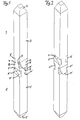
- the contact pin shown in Fig. 1 and having a square cross-section has two halves, 1, 1', each having a tip 2, 2' in the shape of a truncated pyramid, a stem section 3, 3' having an essentially constant cross-section in the longitudinal direction of the pin, and a wing section 4, 4' having a pair of wings 5, 5' situated opposite one another.
- the wings 5 are oriented in the opposite direction to the wings 5'.
- the essentially trapezoidal top faces 6, 6' of the wings 5, 5' merge at their broad side with a surface of the plug-in section 1 and 1', respectively.
- the narrow side of the trapezium is respectively adjoined by a retaining face 7, 7', which is oriented essentially perpendicularly to the longitudinal axis L.
- the retaining wings projecting beyond the surface of the stem sections 3, 3' have been formed by material having been displaced, for example, by an embossing tool from the volume illustrated by dashed lines at 9. Lying between the mutually facing retaining faces 7, 7' is a section 8 whose cross-section corresponds to that of the stem sections 3, 3' and whose length can be defined depending on the length of the chamber of the connector body in which the pin is to be mounted.
- Fig. 2 shows a second embodiment of the contact pin according to the invention.
- This contact pin differs from that shown in Fig. 1 by virtue of the fact that the retaining faces 7, 7' of the pairs of wings 5, 5' are remote from one another.
- this second embodiment affords greater protection against lateral tilting of the pins.
- a higher loadability in the direction of the pin axis can be achieved with the first embodiment since the retaining faces come to lie nearer to the centre of the chamber 10 of the connector body in the case of said first embodiment.
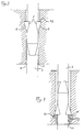
- Figs. 3 and 4 in each case show a side view of the middle region of a contact pin according to the second embodiment.
- the pin shown in Fig. 3 has been plugged into the chamber 10 from the top.
- the cross-section of the stem section 3 is somewhat smaller than that of the chamber 10, with the result that a small clearance 11 exists between the wall of the chamber and the pin.
- Fig. 4 shows the same pin turned through 90°. It is evident that the retaining faces 7' have pushed material in front of themselves during the press-fitting operation. The clearance 1 has largely disappeared at these sides of the pin, instead the displaced, compressed material 13 presses both against the retaining faces 7' and against the walls of the pin and, as a result, further reinforces the anchoring of the said pin.
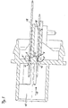
- Fig. 5 shows a male strip connector having contact pins according to the invention.
- the male strip connector has a plugging side 15 for plugging together with a female strip connector (not shown) and has chambers 10 which are provided with entry chamfers 16 and serve to receive the contact pins.
- the latter are press-fitted in the direction of the arrow 17, the pair of wings 5' oriented counter to the press-fitting direction 17 being oriented transversely with respect to the longitudinal direction of the male strip connector.
- the wings 5, 5' are preferably arranged, in the press-fitting direction, in the centre of the chamber 10 or before that.
- the pins In order to complete the male strip connector shown, the pins must still be bent away at right angles, following the contour of the male strip connector, in the regions designated by 18, as a result of which they are additionally protected against being drawn out.
Landscapes
- Connector Housings Or Holding Contact Members (AREA)
- Coupling Device And Connection With Printed Circuit (AREA)
- Details Of Connecting Devices For Male And Female Coupling (AREA)
Description
- The present invention relates to a contact pin which can be plugged into a receiving chamber of a connector body or can be inserted into a mould for the production of a connector body and subsequently be encapsulated by injection moulding, in order to form a connector element in the form of a pin cup, male strip connector or the like, and also to a connector having such contact pins.
- Document
US 5,147,227 discloses a round contact pin having two sets of outwardly projecting nibs on a cylindrical section of the pin, which nibs include flat edge surfaces normal to the axis of the contact pin. The nibs have a rounded, semi-circular shape and the pin is rolled from a piece of sheet metal. The rounded shape of the nibs makes the production of the same relatively complex. - Document
EP-A-0 647 986 discloses a contact pin according to the preamble ofclaim 1. - In order to anchor pins of this type in the connector body,
EP-A-0 647 986 discloses providing them with at least two pairs of lateral retaining wings situated opposite one another on the contact pin. The contact pins are press-fitted from the connection side into receiving chambers of a male strip connector or the like. In the process, top faces which diverge in the shape of a wedge on the retaining wings displace part of the material surrounding the chamber. After the passage of the retaining wings, some of the material returns to its initial position. In the process, it comes to lie on retaining faces at the rear side of the wings and in this way produces resistance against the pin being forced out counter to the press-fitting direction. This resistance can be improved only to a limited extent by the use of a stronger material, because the stronger the material is, the smaller is the portion which returns to the initial position and forms the support for the retaining faces. For this reason, pins can easily be forced out when the male strip connector is plugged together with a complementary female strip connector, which may lead to the failure of assemblies or equipment. The overall loadability could be improved if the wings could be enlarged. However, this is not practical for a number of reasons. - The larger the wings are, the higher, too, are the stresses which occur when the pins are press-fitted into the connector body. This can easily lead to the body buckling or even tearing, particularly in the case of multi-pole miniature connectors, which contain a large number of closely adjacent contact pins. Moreover, if the wings are produced by embossing the pin material, their size is limited by the material cross-section available for deformation.
- The loadability of the known pin in the plugging direction frequently does not satisfy the relevant requirements.
- The object of the invention is to specify a contact pin for a connector which withstands high plugging force loading, yet when it is press-fitted into a connector body, it causes only minimal stresses therein.
- It is additionally intended to specify a connector element having highly loadable contact pins.
- These objects are achieved by means of
Claims - During the press-fitting operation, the pair of wings oriented in the press-fitting direction acts in the known manner described above as protection against the pin being torn out.
- The pair of wings oriented counter to the press-fitting direction, on the other hand, pushes material of the connector body in front of it, compresses the said material and, in this way, automatically produces for itself a stable support in the chamber.
- In this way, the pin is well secured against displacement in the connector body in both directions. In particular, the loadability in the plugging direction is increased by a factor of 2 - 3 compared with the conventional pin. Since the wings may be smaller than in the prior art for the purpose of obtaining sufficient anchoring, the loading of the connector body by material which is laterally displaced during the press-fitting operation can be kept significantly lower, with the result that there is no longer a risk of the connector body being deformed or bursting.
- The retaining wings of the first pair are preferably rotated about the longitudinal axis of the pin through approximately 90° with respect to the wings of the second pair.
- The contact pins can be produced automatically from wire having a round or, preferably, square cross-section. The retaining wings can be produced by embossing.
- Further features and advantages of the invention emerge from the following description of an exemplary embodiment with reference to the figures, in which:
- Fig. 1
- shows a perspective illustration of one embodiment of a contact pin,
- Fig. 2
- shows a second embodiment of the contact pin,
- Figs. 3 and 4
- show a partial section through a connector body which illustrates the method of operation of the invention,
- Fig. 5
- shows a section through a male strip connector as an example of a connector element according to the invention.
- The contact pin shown in Fig. 1 and having a square cross-section has two halves, 1, 1', each having a tip 2, 2' in the shape of a truncated pyramid, a
stem section 3, 3' having an essentially constant cross-section in the longitudinal direction of the pin, and awing section 4, 4' having a pair ofwings 5, 5' situated opposite one another. Thewings 5 are oriented in the opposite direction to the wings 5'. The essentially trapezoidal top faces 6, 6' of thewings 5, 5' merge at their broad side with a surface of the plug-insection 1 and 1', respectively. The narrow side of the trapezium is respectively adjoined by aretaining face 7, 7', which is oriented essentially perpendicularly to the longitudinal axis L. The retaining wings projecting beyond the surface of thestem sections 3, 3' have been formed by material having been displaced, for example, by an embossing tool from the volume illustrated by dashed lines at 9. Lying between the mutually facing retainingfaces 7, 7' is asection 8 whose cross-section corresponds to that of thestem sections 3, 3' and whose length can be defined depending on the length of the chamber of the connector body in which the pin is to be mounted. - Fig. 2 shows a second embodiment of the contact pin according to the invention. This contact pin differs from that shown in Fig. 1 by virtue of the fact that the retaining faces 7, 7' of the pairs of
wings 5, 5' are remote from one another. On account of the relatively large distance between theretaining faces 7, 7' of the two pairs of wings, this second embodiment affords greater protection against lateral tilting of the pins. A higher loadability in the direction of the pin axis can be achieved with the first embodiment since the retaining faces come to lie nearer to the centre of thechamber 10 of the connector body in the case of said first embodiment. - Figs. 3 and 4 in each case show a side view of the middle region of a contact pin according to the second embodiment.
- The method of operation of the contact pin will be explained with reference to these figures.
- The pin shown in Fig. 3 has been plugged into the
chamber 10 from the top. As is evident in the lower region of the figure, the cross-section of thestem section 3 is somewhat smaller than that of thechamber 10, with the result that asmall clearance 11 exists between the wall of the chamber and the pin. When thewings 5 are pressed in, material is initially displaced laterally by thetop faces 6 and then flows back, thereby producing anabutment 12 on the retaining faces which protects the pin against being drawn out. - Fig. 4 shows the same pin turned through 90°. It is evident that the retaining faces 7' have pushed material in front of themselves during the press-fitting operation. The
clearance 1 has largely disappeared at these sides of the pin, instead the displaced, compressedmaterial 13 presses both against the retaining faces 7' and against the walls of the pin and, as a result, further reinforces the anchoring of the said pin. - Fig. 5 shows a male strip connector having contact pins according to the invention. The male strip connector has a plugging
side 15 for plugging together with a female strip connector (not shown) and haschambers 10 which are provided withentry chamfers 16 and serve to receive the contact pins. The latter are press-fitted in the direction of thearrow 17, the pair of wings 5' oriented counter to the press-fittingdirection 17 being oriented transversely with respect to the longitudinal direction of the male strip connector. Thewings 5, 5' are preferably arranged, in the press-fitting direction, in the centre of thechamber 10 or before that. In order to complete the male strip connector shown, the pins must still be bent away at right angles, following the contour of the male strip connector, in the regions designated by 18, as a result of which they are additionally protected against being drawn out.
Claims (6)
- Contact pin for a connector, having an essentially square cross-section and at least two pairs of lateral retaining wings (5, 5') situated opposite one another on the contact pin,
characterised in that
a first pair of retaining wings (5) is arranged in the opposite direction to a second pair (5') and wherein the retaining wings (5, 5') have essentially trapezoidal top faces (6, 6'), whereby the broad side of the trapezoidal top face (6, 6') merges with a surface of the contact pin and the narrow side is adjoined by a retaining face (7, 7'). - Contact pin according to Claim 1, characterized in that the wings of the first pair (5) are rotated about the longitudinal axis (L) of the pin through approximately 90° with respect to the wings of the second pair (5').
- Contact pin according to Claim 1 or 2, characterized in that the retaining wings (5, 5') are formed by embossing.
- Contact pin according to one of Claims 1 to 3, characterized in that the retaining wings each have a retaining face (7, 7') which is essentially perpendicular to the longitudinal axis of the contact pin, and in that the retaining faces (7) of the wings (5) of a first pair face those of a second pair (5') with a predetermined spacing (8).
- Contact pin according to one of Claims 1 to 4, characterized in that the retaining wings each have a retaining face (7, 7') which is essentially perpendicular to the longitudinal axis of the contact pin, and in that the retaining faces (7) of the wings (5) of a first pair are remote from those of a second pair (5').
- Connector element having at least one contact pin according to one of claims 1 to 5, which is press-fitted into a chamber of a connector body, is held on supports and has at least one pair of retaining wings (5), characterized in that the supports are formed from connector material which is displaced counter to the orientation of the retaining wings when the contact pin is press-fitted.
Applications Claiming Priority (2)
| Application Number | Priority Date | Filing Date | Title |
|---|---|---|---|
| DE29700452U | 1997-01-13 | ||
| DE29700452U DE29700452U1 (en) | 1997-01-13 | 1997-01-13 | Contact pin with opposite anchoring wings and connector element |
Publications (3)
| Publication Number | Publication Date |
|---|---|
| EP0854542A2 EP0854542A2 (en) | 1998-07-22 |
| EP0854542A3 EP0854542A3 (en) | 1999-10-13 |
| EP0854542B1 true EP0854542B1 (en) | 2007-11-21 |
Family
ID=8034457
Family Applications (1)
| Application Number | Title | Priority Date | Filing Date |
|---|---|---|---|
| EP97121662A Expired - Lifetime EP0854542B1 (en) | 1997-01-13 | 1997-12-09 | Contact pin having anchoring wings in opposite directions, and connector element |
Country Status (4)
| Country | Link |
|---|---|
| US (1) | US6152782A (en) |
| EP (1) | EP0854542B1 (en) |
| DE (2) | DE29700452U1 (en) |
| ES (1) | ES2296302T3 (en) |
Families Citing this family (27)
| Publication number | Priority date | Publication date | Assignee | Title |
|---|---|---|---|---|
| JP3503877B2 (en) * | 1999-02-19 | 2004-03-08 | 矢崎総業株式会社 | Terminal structure for board using square wire |
| DE10222265B4 (en) * | 2002-05-18 | 2013-02-07 | Preh Gmbh | Leitkleberverbindung |
| JP2004164932A (en) * | 2002-11-11 | 2004-06-10 | Sumitomo Wiring Syst Ltd | Connector |
| US6896559B2 (en) * | 2003-03-14 | 2005-05-24 | Tyco Electronics Corporation | Pin retention apparatus, methods and articles of manufacture |
| TW566695U (en) * | 2003-04-11 | 2003-12-11 | Hon Hai Prec Ind Co Ltd | Electrical connector contact |
| JP2004362814A (en) * | 2003-06-02 | 2004-12-24 | Sumitomo Wiring Syst Ltd | Connector and terminal fitting |
| JP4179170B2 (en) * | 2004-01-16 | 2008-11-12 | 住友電装株式会社 | connector |
| JP2005353371A (en) * | 2004-06-09 | 2005-12-22 | Tyco Electronics Amp Kk | Terminal press fit structure |
| DE102006036884B4 (en) * | 2006-08-04 | 2008-07-03 | Erni Electronics Gmbh | Connectors |
| DE102006055694B3 (en) * | 2006-11-23 | 2008-03-27 | Erni Electronics Gmbh | Plug-in connector, has guiding groove provided on side of contact unit support and comprising counter bearing at front end for alternative mounting of contact unit in position rotated around specific degrees |
| JP4971957B2 (en) * | 2007-11-29 | 2012-07-11 | タイコエレクトロニクスジャパン合同会社 | Contact member, contact member holding structure and electrical connector |
| JP5547508B2 (en) * | 2010-02-03 | 2014-07-16 | 矢崎総業株式会社 | Method for manufacturing terminal having press-fitting engagement portion |
| US8951066B2 (en) * | 2011-07-22 | 2015-02-10 | Lear Corporation | Electrical connector |
| CN104205507B (en) | 2012-02-07 | 2017-06-13 | 3M创新有限公司 | Board mounted electrical connector |
| JP2015511379A (en) | 2012-02-07 | 2015-04-16 | スリーエム イノベイティブ プロパティズ カンパニー | Electrical connector contact terminal |
| EP2812952A4 (en) | 2012-02-07 | 2015-09-30 | 3M Innovative Properties Co | Electrical connector strain relief |
| US9509089B2 (en) | 2012-02-07 | 2016-11-29 | 3M Innovative Properties Company | Electrical connector latch |
| CN104170172B (en) | 2012-02-07 | 2017-06-09 | 3M创新有限公司 | Wire rod installs electric connector |
| DE102012222364A1 (en) * | 2012-12-05 | 2014-06-05 | E.G.O. Elektro-Gerätebau GmbH | Connector and device with such a connector |
| JP6427348B2 (en) * | 2014-07-16 | 2018-11-21 | 矢崎総業株式会社 | connector |
| US9537278B2 (en) * | 2015-02-09 | 2017-01-03 | Yazaki Corporation | Terminal group and connector |
| JP6550890B2 (en) * | 2015-04-22 | 2019-07-31 | 住友電装株式会社 | Press-fit terminal |
| CN205960262U (en) * | 2016-07-06 | 2017-02-15 | 泰科电子(上海)有限公司 | Connection terminal and electric connector |
| DE102017111293A1 (en) | 2017-05-23 | 2018-11-29 | Te Connectivity Germany Gmbh | pin |
| JP7027932B2 (en) * | 2018-02-14 | 2022-03-02 | 住友電装株式会社 | Press-fit terminal |
| JP7191380B2 (en) * | 2019-06-21 | 2022-12-19 | 日本圧着端子製造株式会社 | connector |
| CN213520383U (en) * | 2020-07-20 | 2021-06-22 | 泰科电子(上海)有限公司 | Conductive terminal |
Family Cites Families (6)
| Publication number | Priority date | Publication date | Assignee | Title |
|---|---|---|---|---|
| DE647986C (en) * | 1936-03-01 | 1937-07-17 | Jacob Horn | Device for round grinding of pearls |
| DE3302824A1 (en) * | 1983-01-28 | 1984-08-02 | Grote & Hartmann | ADDITIONAL LOCKING ELEMENT FOR ROUND CONNECTORS |
| US5035656A (en) * | 1990-05-15 | 1991-07-30 | E. I. Du Pont De Nemours And Company | Connector, circuit board contact element and retention portion |
| US5064389A (en) * | 1991-06-19 | 1991-11-12 | Amp Incorporated | Electrical slave connector |
| US5147227A (en) * | 1991-10-17 | 1992-09-15 | Amp Incorporated | Terminal retention device |
| DE9314676U1 (en) * | 1993-09-28 | 1994-02-24 | Siemens AG, 80333 München | Contact pin for plug connections |
-
1997
- 1997-01-13 DE DE29700452U patent/DE29700452U1/en not_active Expired - Lifetime
- 1997-12-09 DE DE69738308T patent/DE69738308T2/en not_active Expired - Lifetime
- 1997-12-09 EP EP97121662A patent/EP0854542B1/en not_active Expired - Lifetime
- 1997-12-09 ES ES97121662T patent/ES2296302T3/en not_active Expired - Lifetime
-
1998
- 1998-01-13 US US09/006,110 patent/US6152782A/en not_active Expired - Fee Related
Also Published As
| Publication number | Publication date |
|---|---|
| US6152782A (en) | 2000-11-28 |
| ES2296302T3 (en) | 2008-04-16 |
| DE29700452U1 (en) | 1997-02-27 |
| DE69738308T2 (en) | 2008-10-02 |
| EP0854542A2 (en) | 1998-07-22 |
| DE69738308D1 (en) | 2008-01-03 |
| EP0854542A3 (en) | 1999-10-13 |
Similar Documents
| Publication | Publication Date | Title |
|---|---|---|
| US6152782A (en) | Contact pin having anchoring wings in opposite directions, and connector elements | |
| JP3724610B2 (en) | Terminal bracket cover | |
| EP0333837B1 (en) | Connector with compressible insulative body | |
| EP1215765B1 (en) | Female crimp terminal | |
| EP1425825B1 (en) | Electrical connector | |
| US4416504A (en) | Contact with dual cantilevered arms with narrowed, complimentary tip portions | |
| US4906212A (en) | Electrical pin and socket connector | |
| US4591230A (en) | Electrical connector receptacle | |
| US5980336A (en) | Electrical terminal | |
| US6024612A (en) | Receptacle contact | |
| US5620345A (en) | High density pin and socket electrical connector | |
| US6488550B1 (en) | Connector contact and method of manufacturing the same | |
| EP2157669A1 (en) | A connector and assembling method therefor | |
| JP2008124043A (en) | Female electrical contact terminal with controlled contact pressure | |
| US6729904B2 (en) | Terminal fitting and a connector provided therewith | |
| JPH06260248A (en) | Low insertion power electric connector | |
| EP1376769B1 (en) | Connector with resilient locking member | |
| US20060121797A1 (en) | Electrical contact terminal comprising an elastic contact blade | |
| EP1294056B1 (en) | Terminal fitting, connector provided therewith and method for producing the terminal fitting | |
| US6817904B2 (en) | Connector and a method for inserting a terminal fitting thereinto | |
| EP1689034B1 (en) | A terminal fitting, connector provided therewith and method of forming a terminal fitting | |
| EP0476848B1 (en) | Closed entry socket contact assembly | |
| US6749470B2 (en) | Connector | |
| US5611716A (en) | Electrical contact having improved secondary locking surfaces | |
| JP3561464B2 (en) | Male contact |
Legal Events
| Date | Code | Title | Description |
|---|---|---|---|
| PUAI | Public reference made under article 153(3) epc to a published international application that has entered the european phase |
Free format text: ORIGINAL CODE: 0009012 |
|
| AK | Designated contracting states |
Kind code of ref document: A2 Designated state(s): AT BE DE ES FR GB IT SE |
|
| AX | Request for extension of the european patent |
Free format text: AL;LT;LV;MK;RO;SI |
|
| PUAL | Search report despatched |
Free format text: ORIGINAL CODE: 0009013 |
|
| AK | Designated contracting states |
Kind code of ref document: A3 Designated state(s): AT BE CH DE DK ES FI FR GB GR IE IT LI LU MC NL PT SE |
|
| AX | Request for extension of the european patent |
Free format text: AL;LT;LV;MK;RO;SI |
|
| 17P | Request for examination filed |
Effective date: 19991215 |
|
| AKX | Designation fees paid |
Free format text: AT BE DE ES FR GB IT SE |
|
| 17Q | First examination report despatched |
Effective date: 20051010 |
|
| GRAP | Despatch of communication of intention to grant a patent |
Free format text: ORIGINAL CODE: EPIDOSNIGR1 |
|
| GRAS | Grant fee paid |
Free format text: ORIGINAL CODE: EPIDOSNIGR3 |
|
| GRAA | (expected) grant |
Free format text: ORIGINAL CODE: 0009210 |
|
| RAP1 | Party data changed (applicant data changed or rights of an application transferred) |
Owner name: FCI |
|
| AK | Designated contracting states |
Kind code of ref document: B1 Designated state(s): AT BE DE ES FR GB IT SE |
|
| REG | Reference to a national code |
Ref country code: GB Ref legal event code: FG4D |
|
| REF | Corresponds to: |
Ref document number: 69738308 Country of ref document: DE Date of ref document: 20080103 Kind code of ref document: P |
|
| REG | Reference to a national code |
Ref country code: ES Ref legal event code: FG2A Ref document number: 2296302 Country of ref document: ES Kind code of ref document: T3 |
|
| PG25 | Lapsed in a contracting state [announced via postgrant information from national office to epo] |
Ref country code: SE Free format text: LAPSE BECAUSE OF FAILURE TO SUBMIT A TRANSLATION OF THE DESCRIPTION OR TO PAY THE FEE WITHIN THE PRESCRIBED TIME-LIMIT Effective date: 20080221 |
|
| PG25 | Lapsed in a contracting state [announced via postgrant information from national office to epo] |
Ref country code: AT Free format text: LAPSE BECAUSE OF FAILURE TO SUBMIT A TRANSLATION OF THE DESCRIPTION OR TO PAY THE FEE WITHIN THE PRESCRIBED TIME-LIMIT Effective date: 20071121 |
|
| ET | Fr: translation filed | ||
| PG25 | Lapsed in a contracting state [announced via postgrant information from national office to epo] |
Ref country code: BE Free format text: LAPSE BECAUSE OF FAILURE TO SUBMIT A TRANSLATION OF THE DESCRIPTION OR TO PAY THE FEE WITHIN THE PRESCRIBED TIME-LIMIT Effective date: 20071121 |
|
| PLBE | No opposition filed within time limit |
Free format text: ORIGINAL CODE: 0009261 |
|
| STAA | Information on the status of an ep patent application or granted ep patent |
Free format text: STATUS: NO OPPOSITION FILED WITHIN TIME LIMIT |
|
| 26N | No opposition filed |
Effective date: 20080822 |
|
| GBPC | Gb: european patent ceased through non-payment of renewal fee |
Effective date: 20080221 |
|
| PG25 | Lapsed in a contracting state [announced via postgrant information from national office to epo] |
Ref country code: GB Free format text: LAPSE BECAUSE OF NON-PAYMENT OF DUE FEES Effective date: 20080221 |
|
| PGFP | Annual fee paid to national office [announced via postgrant information from national office to epo] |
Ref country code: ES Payment date: 20091214 Year of fee payment: 13 |
|
| PGFP | Annual fee paid to national office [announced via postgrant information from national office to epo] |
Ref country code: DE Payment date: 20091230 Year of fee payment: 13 |
|
| PG25 | Lapsed in a contracting state [announced via postgrant information from national office to epo] |
Ref country code: IT Free format text: LAPSE BECAUSE OF NON-PAYMENT OF DUE FEES Effective date: 20071231 |
|
| REG | Reference to a national code |
Ref country code: FR Ref legal event code: TP Owner name: FCI AUTOMOTIVE HOLDING, FR Effective date: 20110912 Ref country code: FR Ref legal event code: CD Owner name: FCI AUTOMOTIVE HOLDING, FR Effective date: 20110912 |
|
| REG | Reference to a national code |
Ref country code: DE Ref legal event code: R119 Ref document number: 69738308 Country of ref document: DE Effective date: 20110701 |
|
| PG25 | Lapsed in a contracting state [announced via postgrant information from national office to epo] |
Ref country code: DE Free format text: LAPSE BECAUSE OF NON-PAYMENT OF DUE FEES Effective date: 20110701 |
|
| REG | Reference to a national code |
Ref country code: FR Ref legal event code: GC Effective date: 20111020 |
|
| REG | Reference to a national code |
Ref country code: ES Ref legal event code: FD2A Effective date: 20120220 |
|
| PG25 | Lapsed in a contracting state [announced via postgrant information from national office to epo] |
Ref country code: ES Free format text: LAPSE BECAUSE OF NON-PAYMENT OF DUE FEES Effective date: 20101210 |
|
| REG | Reference to a national code |
Ref country code: DE Ref legal event code: R082 Ref document number: 69738308 Country of ref document: DE Representative=s name: BARDEHLE PAGENBERG PARTNERSCHAFT MBB PATENTANW, DE Effective date: 20120419 Ref country code: DE Ref legal event code: R082 Ref document number: 69738308 Country of ref document: DE Representative=s name: BARDEHLE PAGENBERG PARTNERSCHAFT PATENTANWAELT, DE Effective date: 20120419 Ref country code: DE Ref legal event code: R082 Ref document number: 69738308 Country of ref document: DE Representative=s name: PATENT- UND RECHTSANWAELTE BARDEHLE PAGENBERG, DE Effective date: 20120419 Ref country code: DE Ref legal event code: R081 Ref document number: 69738308 Country of ref document: DE Owner name: FCI AUTOMOTIVE HOLDING, FR Free format text: FORMER OWNER: FCI, VERSAILLES, FR Effective date: 20120419 |
|
| REG | Reference to a national code |
Ref country code: DE Ref legal event code: R082 Ref document number: 69738308 Country of ref document: DE Representative=s name: PATENT- UND RECHTSANWAELTE BARDEHLE PAGENBERG, DE |
|
| REG | Reference to a national code |
Ref country code: DE Ref legal event code: R082 Ref document number: 69738308 Country of ref document: DE Representative=s name: BARDEHLE PAGENBERG PARTNERSCHAFT MBB PATENTANW, DE Effective date: 20120629 Ref country code: DE Ref legal event code: R082 Ref document number: 69738308 Country of ref document: DE Representative=s name: BARDEHLE PAGENBERG PARTNERSCHAFT PATENTANWAELT, DE Effective date: 20120629 Ref country code: DE Ref legal event code: R081 Ref document number: 69738308 Country of ref document: DE Owner name: FCI AUTOMOTIVE HOLDING, FR Free format text: FORMER OWNER: FCI, GUYANCOURT, FR Effective date: 20120629 |
|
| REG | Reference to a national code |
Ref country code: FR Ref legal event code: TP Owner name: DELPHI INTERNATIONAL OPERATIONS LUXEMBOURG S.A, LU Effective date: 20140715 |
|
| REG | Reference to a national code |
Ref country code: FR Ref legal event code: PLFP Year of fee payment: 19 |
|
| REG | Reference to a national code |
Ref country code: FR Ref legal event code: PLFP Year of fee payment: 20 |
|
| PGFP | Annual fee paid to national office [announced via postgrant information from national office to epo] |
Ref country code: FR Payment date: 20161227 Year of fee payment: 20 |