EP0854400B1 - Toner projection system - Google Patents
Toner projection system Download PDFInfo
- Publication number
- EP0854400B1 EP0854400B1 EP97110050A EP97110050A EP0854400B1 EP 0854400 B1 EP0854400 B1 EP 0854400B1 EP 97110050 A EP97110050 A EP 97110050A EP 97110050 A EP97110050 A EP 97110050A EP 0854400 B1 EP0854400 B1 EP 0854400B1
- Authority
- EP
- European Patent Office
- Prior art keywords
- electrode
- voltage
- electrodes
- toner
- projection
- Prior art date
- Legal status (The legal status is an assumption and is not a legal conclusion. Google has not performed a legal analysis and makes no representation as to the accuracy of the status listed.)
- Expired - Lifetime
Links
Images


Classifications
-
- B—PERFORMING OPERATIONS; TRANSPORTING
- B41—PRINTING; LINING MACHINES; TYPEWRITERS; STAMPS
- B41J—TYPEWRITERS; SELECTIVE PRINTING MECHANISMS, i.e. MECHANISMS PRINTING OTHERWISE THAN FROM A FORME; CORRECTION OF TYPOGRAPHICAL ERRORS
- B41J2/00—Typewriters or selective printing mechanisms characterised by the printing or marking process for which they are designed
- B41J2/385—Typewriters or selective printing mechanisms characterised by the printing or marking process for which they are designed characterised by selective supply of electric current or selective application of magnetism to a printing or impression-transfer material
- B41J2/41—Typewriters or selective printing mechanisms characterised by the printing or marking process for which they are designed characterised by selective supply of electric current or selective application of magnetism to a printing or impression-transfer material for electrostatic printing
- B41J2/415—Typewriters or selective printing mechanisms characterised by the printing or marking process for which they are designed characterised by selective supply of electric current or selective application of magnetism to a printing or impression-transfer material for electrostatic printing by passing charged particles through a hole or a slit
- B41J2/4155—Typewriters or selective printing mechanisms characterised by the printing or marking process for which they are designed characterised by selective supply of electric current or selective application of magnetism to a printing or impression-transfer material for electrostatic printing by passing charged particles through a hole or a slit for direct electrostatic printing [DEP]
-
- G—PHYSICS
- G03—PHOTOGRAPHY; CINEMATOGRAPHY; ANALOGOUS TECHNIQUES USING WAVES OTHER THAN OPTICAL WAVES; ELECTROGRAPHY; HOLOGRAPHY
- G03G—ELECTROGRAPHY; ELECTROPHOTOGRAPHY; MAGNETOGRAPHY
- G03G15/00—Apparatus for electrographic processes using a charge pattern
- G03G15/22—Apparatus for electrographic processes using a charge pattern involving the combination of more than one step according to groups G03G13/02 - G03G13/20
- G03G15/34—Apparatus for electrographic processes using a charge pattern involving the combination of more than one step according to groups G03G13/02 - G03G13/20 in which the powder image is formed directly on the recording material, e.g. by using a liquid toner
- G03G15/344—Apparatus for electrographic processes using a charge pattern involving the combination of more than one step according to groups G03G13/02 - G03G13/20 in which the powder image is formed directly on the recording material, e.g. by using a liquid toner by selectively transferring the powder to the recording medium, e.g. by using a LED array
- G03G15/346—Apparatus for electrographic processes using a charge pattern involving the combination of more than one step according to groups G03G13/02 - G03G13/20 in which the powder image is formed directly on the recording material, e.g. by using a liquid toner by selectively transferring the powder to the recording medium, e.g. by using a LED array by modulating the powder through holes or a slit
-
- G—PHYSICS
- G03—PHOTOGRAPHY; CINEMATOGRAPHY; ANALOGOUS TECHNIQUES USING WAVES OTHER THAN OPTICAL WAVES; ELECTROGRAPHY; HOLOGRAPHY
- G03G—ELECTROGRAPHY; ELECTROPHOTOGRAPHY; MAGNETOGRAPHY
- G03G2217/00—Details of electrographic processes using patterns other than charge patterns
- G03G2217/0008—Process where toner image is produced by controlling which part of the toner should move to the image- carrying member
- G03G2217/0025—Process where toner image is produced by controlling which part of the toner should move to the image- carrying member where the toner starts moving from behind the electrode array, e.g. a mask of holes
Description
- The invention relates to a system for projecting electrically conductive or semi-conductive black or colored toners directly on to a print media.
- Conventional printers using dry toners typically employ electrophotographic components to create and develop the desired image on paper or other print media. In electrophotography, a latent image is created on the surface of a photoconducting material by selectively exposing areas of the surface to light. A difference in electrostatic charge density is thereby created between the exposed and unexposed areas on the surface of the photoconductor. The visible image is developed by electrostatic toners containing pigmented components which are usually dispersed in an insulating binder and transferred to the photoconductor via a toner delivery system. The photoconductor and toner particles are oppositely charged, or have different levels of the same charge, and the toner particles are electrostatically attracted to or repelled from either the exposed or unexposed areas on the surface of the photoconductor. A sheet of paper or an intermediate transfer medium is then given an electrostatic charge opposite that of the toner and passed in close proximity to the photoconductor to attract the toner from the photoconductor on to the paper or intermediate medium in the pattern of the image developed on the photoconductor.
- It would be a significant advantage in the use of dry toner printers to project the dry toner from a print head directly on to the paper to form the desired images thereon. This direct projection would eliminate the need for a photoconductor and the associated indirect transfer mechanisms used in conventional electrophotographic printers. It would also be advantageous to use conductive or semi-conductive toners to help reduce the degradation of print quality caused by counter-electrostatic field forces that can act to divert toner trajectories in conventional print mechanisms. Such forces are particularly evident in dry toner color printers. The use of conductive or semi-conductive toners could also reduce or eliminate problems caused by "wrong sign" toner and make the print process less sensitive to varying levels of paper thickness and resistivity.
- GB 2 108 432 A describes an printing apparatus having a controller formed of a first electrode, an insulating layer, and a third electrode. An opening in the first electrode, an opening in the insulating layer and an opening in the second electrode are aligned with each other. By applying a voltage between adjacent electrodes the charged particles move between the two electrodes. By further applying a voltage between the two electrodes of the controller passage of the particles through the openings of the controllers is possible.
- It is the object of the present invention to provide an improved toner projection device and method for projecting dry toner directly onto paper or other print media, thereby eliminating the need for a photoconductor and there is a associated indirect transfer mechanisms used in conventional electrophotographic printers.
- This object is achieved by a toner projection device of claim 1 or claim 4, and by a method of claim 7.
- According to a further aspect of the invention, an image forming device having the inventive toner projection device is formed.
- The present invention enables the use of conductive or semi-conductive toners in a direct projection printing device to help reduce the degradation of print quality caused by counter-electrostatic field forces that divert toner trajectories in conventional print mechanisms, eliminate problems caused by "wrong sign" toner, and make the print process less sensitive to varying levels of paper thickness resistivity.
- The present invention provides a new toner projection system that generates a toner cloud within a print head structure and selectively projects toner particles on to paper or other print media.
- The present invention is a novel system for projecting conductive or semi-conductive toner directly on to paper or another image receiving member. In one embodiment of the invention, a direct electrostatic projection printing device includes a reference electrode, an orifice plate and a projection control electrode interposed between the reference electrode and the orifice plate. An alternating electric field is generated between the reference electrode and the orifice plate to form a cloud of toner particles between the reference electrode and the orifice plate. An electric field is also generated intermittently between the projection control electrode and the orifice plate to project toner particles through the orifice plate on to a sheet of paper or other image receiving member. In one preferred embodiment, the first electric field is an alternating electric field generated by applying an a.c. voltage to the reference electrode and the orifice plate. The second electric field is generated by intermittently applying a d.c. voltage to the projection control electrode at select intervals to selectively project toner particles through the orifice plate. The system can be configured as a full width printing array that includes a series of projection control electrodes and an array of orifices in the orifice plate. Each projection control electrode is aligned with one or more of the orifices in the orifice plate. A control mechanism is used to selectively and intermittently apply a d.c. voltage to the projection control electrodes to project toner through the orifice plate in a predetermined pattern. The control mechanism may include, for example, a series of switches connected between the projection control electrodes and a source of d.c. projection voltage. Alternatively, a pulse generator, or a series of pulse generators, could be used to control the d.c. voltage applied to the projection electrodes.
- The toner projection system summarized above can be combined with conventional printer control components to form a direct projection printer. In this embodiment of the invention, the printer includes a formatter that supplies data representing a desired print image to the print engine. The print engine, which is operatively coupled to the formatter, projects an image directly on to the paper. A paper supply mechanism supplies paper to the print engine and a paper output mechanism outputs the printed pages from the print engine. The print engine includes the projector described above -- a reference electrode, an orifice plate and a projection control electrode interposed between the reference electrode and the orifice plate. Again, alternating electric field is generated between the reference electrode and the orifice plate to form a cloud of toner particles within the projector. An electric field is generated intermittently between the projection control electrode and the orifice plate to project toner particles through the orifice plate on to a sheet of paper to print the desired image according to the data supplied by the formatter.
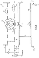
- Fig. 1 is a cross-sectional representation of the basic components of a toner projection system that uses a switch to control the application of the projection voltage to the projection control electrode.
- Fig. 2 is a cross-sectional representation of the basic components of a toner projection system that uses a pulse generator to control the application of the projection voltage to the projection control electrode.
- Fig. 3 is a top down plan view of one exemplary configuration of an array of orifices and projection control electrodes.
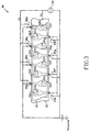
- Fig. 4 is a top down plan view of a second exemplary configuration of an array of orifices and projection control electrodes.
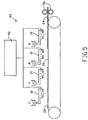
- Fig. 5 is a diagrammatic representation of a direct electrostatic projection printer.
- The basic components of the toner projection system or "projector" are illustrated in Fig. 1.
Projector 10 includes afirst electrode 12, asecond electrode 16, and athird electrode 20. First, second andthird electrodes reference electrode 12, theprojection control electrode 16, and the orifice plate or "printhead" 20.Projection control electrode 16 is positioned betweenreference electrode 12 andorifice plate 20.Openings 18 inprojection control electrode 16 represent either the spacing betweendiscrete electrodes 16, as best seen in Figs. 2 and 3, or openings through an electrode plate. In either case,openings 18 should not be positioned directly overorifice 22 inorifice plate 20. Optionally,openings 14 are formed inreference electrode 12 so that toner may be introduced intoprojector 10 either above or belowreference electrode 12.Projection control electrode 16 is spaced apart from reference electrode 12 a distance D1. Orificeplate 20 is spaced apart fromprojection control electrode 16 a distance D2. Paper 24 or other print media is positioned oncarrier substrate 26 generally parallel to and spaced apart from orifice plate 20 a distance D3. In a typical projection printing configuration, it is expected that D3 will be about 1 mm. D2 will then be about 0.2mm to 0.3 mm. D1 is, preferably, somewhat greater than D2. -
Reference electrode 12 andorifice plate 20 are connected to asource 28 of voltage V1. Voltage V1 may be an alternating current (a.c.) voltage or a d.c. biased a.c. voltage. In operation,voltage source 28 is turned on to apply voltage V1 to referenceelectrode 12 andorifice plate 20. In the embodiment illustrated in Fig. 1, voltage V1 is an a.c. voltage. When conductive toner particlescontact reference electrode 12 andorifice plate 20, they are charged to the polarity of the voltage applied to those electrodes. The charged toner particles oscillate between the electrodes under the influence of the alternating electric field generated between the first andthird electrodes conductive toner particles 34 introduced into the vicinity ofreference electrode 12 andorifice plate 20 move alternately between those electrodes and throughopenings 18 inprojection control electrode 16 to form acloud 36 of toner particles withinprojector 10. A d.c. projection voltage VPROJECTION is intermittently applied toprojection control electrode 16 at select intervals. In the embodiment illustrated in Fig. 1, VPROJECTION is intermittently applied toprojection control electrode 16 by opening and closingswitch 30. Whenswitch 30 is closed,projection control electrode 16 is connected to source 38 of projection voltage VPROJECTION. Whenswitch 30 is open,projection control electrode 16 is not connected to source 38 of projection voltage VPROJECTION. Preferably,projection control electrode 16 is switched between voltage V1 and projection voltage VPROJECTION. Whenprojection control electrode 16 is connected to V1, it acts to develop and maintaintoner cloud 36 is the manner described above with regard toreference electrode 12 andorifice plate 20. When VPROJECTION is applied toprojection control electrode 16,toner particles 34 are projected throughorifices 22 ontopaper 24. In an alternative embodiment illustrated in Fig. 2, a pulse orsignal generator 39 is used to intermittently apply the d.c. voltage toprojection control electrode 16.Switch 30 andsource 38 in Fig. 1 andpulse generator 39 in Fig. 2 serve as a mechanism for intermittently applying a d.c. voltage toprojection control electrode 16. Each of these mechanisms can be electronically controlled or programmed to apply a d.c. voltage to the projection electrode at select intervals to achieve the desired print pattern. Other suitable control mechanisms could also be used. - The magnitude of projection voltage VPROJECTION is greater than the magnitude of voltage V1. It is expected that, in a typical printing application, the voltage differential between VPROJECTION and V1 will be about 200 volts. Projection voltage VPROJECTION is applied for a time period longer than 1/frequency of the a.c. voltage V1. Projection voltage VPROJECTION can be either polarity when V1 is an a.c. voltage. For example, when VPROJECTION is positive, as shown in Fig. 1, toner particles in contact with
projection control electrode 16 become positively charged. Having thus acquired a positive charge, the toner particles in contact withprojection control electrode 16 are repelled from that electrode and attracted to orificeplate 20 due to the electric field that exists during the time period whenorifice plate 20 is negative or opposite to the polarity of projection voltage VPROJECTION. In this way, toner particles above and adjacent to orifice 22 are projected throughorifice 22 on topaper 24. - The charge on the toner particles will, due to the particles' conductivity, dissipate as the
particles contact paper 24, and thereby reduce or eliminate counter-electrostatic field forces that would be significant when using insulative toners. If desired, a voltage V2 having a polarity opposite the polarity of voltage VPROJECTION may be applied tocarrier substrate 26 to assist in the toner projection trajectory onto the print media. Thereafter, the toner can be fused to the paper using conventional methods and devices well known to those skilled in the art. Application of an a.c. voltage (voltage V1) also helps clean the face of the printhead,orifice plate 20, due to the vibration created by the a.c. voltage. - The velocity of the conductive toner particles moving from
projection control electrode 16 towardorifice plate 20, some of which are projected throughorifice 22 upon application of projection voltage VPROJECTION, is determined according to Equation No. 1. Conductive toner particles, as that term is used in this specification and in the claims, includes conductive and semi-conductive, preferably dry, toner particles. The degree of conductivity of the toner particles may be varied as necessary to achieve the desired operating parameters forprojector 10, as described in more detail below. - vt = velocity of toner particle (meters/sec.)
- ΔV = VPROJECTION - V1 (volts)
- Q = toner charge (coulombs) = 4πεOr2ECRITICAL
- m = toner mass (grams) = (4/3)πr3ρt
- Tm = mechanical contact time constant (sec.)
- Tt = toner charge transfer time constant (sec.) = ktε0ρt
- ρt = toner resistivity (ohm cm)
- kt = dielectric constant
- ε0 = permitivity of free space = 8.85 x 10⁻¹⁴ farads/cm
- r = toner radius (cm)
- ECRITICAL = electrostatic field = 30 x 10 3 volts/cm
- ρt = toner density (gram/cm3)
-
- Optimization of
projector 10 can be achieved according to Equation No. 1 by varying the characteristics of the toner, the magnitude and polarity of the voltages applied to the electrodes and the distances D1, D2, betweenelectrodes orifice plate 20 andpaper 24. For example, a suitable mono-component conductive dry toner particle may have a radius, r, of approximately 5 x 10⁻⁴ cm and a density, ρt, of approximately 1 gram/cm3. Preferably, such toner will be made to have a resistivity of about 104 ohm-cm. A 200 volt voltage differential applied between the second andthird electrodes orifice 22 at a velocity of approximately 2.52 m/sec. This velocity is sufficient to project the toner particles on topaper 24 up to a distance D3 of approximately 1 mm. The preferred range of conductivity of the toner particles, as measured by its resistivity, is 104 ohm-cm to 1010 ohm-cm. - Figs. 3 and 4 show two exemplary configurations for an array of
projection control electrodes 16 andorifice plates 20 such as might be used in a direct projection electrostatic printer. In Fig. 3,projector 10 includes a series of discreteprojection control electrodes 16a-16h positioned over orifices 22a-22h inorifice plate 20. Each projection control electrode is connected alternately to V1 or VPROJECTION throughswitches 30a-30h. The desired image is obtained by projecting toner particles through individual orifices in a predetermined pattern or sequence by controlling the application of VPROJECTION toprojection control electrodes 16a-16h throughswitches 30a-30h, or through another suitable control mechanism as described above. In the array shown in Fig. 4,orifice plate 20 consists of three parallel plates 20a-20c. Orifice plates 20a-20c are connected to V1 throughswitches 31a-31c. Eachprojection control electrode 16a-16j covers a series of orifices 22a, b and c across the three orifice plates. Toner is projected through an individual orifice by simultaneously applying voltage V1 to the proper orifice plate and VPROJECTION to the overlying projection control electrode. For example, toner is projected through orifices 22aa and 22ad in orifice plate 20a by applying V1 to orifice plate 20a and simultaneously applying VPROJECTION toprojection control electrodes projection control electrodes 16a-16j throughswitches 30a-30j. -
Projector 10 can be combined with conventional printer control components to form an image forming apparatus for printing on a page of paper or other print media. Such an image forming apparatus is illustrated schematically in Fig. 5 as an inline color printer 44. Referring to Fig. 5, a plurality ofcolor toner projectors 10 are positioned longitudinally adjacent to one another abovepaper carrier substrate 26. Alternatively, asingle projector 10 could be incorporated into a monochrome printer. Aformatter mechanism 48 is operatively coupled toprojectors 10.Formatter 48supplies projectors 10 with data representing the desired image to be printed on the pages ofpaper 24. In this embodiment of the invention,projectors 10 include an array of independently controlled projection control electrodes that extend acrosspaper 24 such as that illustrated in Fig. 3. Projection voltages are selectively applied to the projection control electrodes according to the data supplied byformatter 48 so that the toner particles are projected at desired locations onpaper 24. - Pages of
paper 24 are transported along and belowprojectors 10 on a transport belt or other suitablepaper carrier substrate 26. The partial color image in each of the black (K), magenta (M), yellow (Y) and cyan (C) color planes are successively and sequentially projected on to the surface ofpaper 26 throughprojectors 10. Thereafter,paper 24 passes between a set offuse rollers 56 to permanently affix the toner image on the paper.Formatter 48,carrier substrate 26 and fuserollers 56 are intended to represent generally the various conventional printer components suitable for electronically formatting the desired image, supplying paper to the print engine (projectors 10) and affixing the toner image on the paper, respectively. - There has been shown and described a novel system for projecting conductive or semi-conductive toner directly on to print media. The direct projection of conductive or semi-conductive toner using the invented projection system is expected to help reduce the degradation of print quality caused by counter-electrostatic field forces that divert toner trajectories in conventional print mechanisms - forces that are particularly evident in dry toner color printers. The invented system allows for the elimination of the toner development and photoconductive drum components used in conventional printers and, should, therefore, reduce the cost of the printer. The apparatus and method of the present invention should also eliminate problems caused by "wrong sign" toner and make the print process less sensitive to varying levels of paper resistivity.
Claims (7)
- A toner projection device (10), comprising:a. a first electrode (12);b. a second electrode (16);c. a third electrode (20);d. an orifice (22) in the third electrode (20);e. the second electrode (16) interposed between the first and third electrodes (12, 20) and having a plurality of openings (18), said openings (18) not positioned over the orifice (22) in the third electrode (20);f. a source (28) of a.c. voltage operatively connected to the first and third electrodes (12, 20); andg. a control means for intermittently applying a d.c. voltage to the second electrode (16).
- The device of Claim 1, wherein the control means comprises:a. a source (38) of d.c. voltage; andb. a switch (30) operatively connected between the second electrode (16) and the source (38) of d.c. voltage, the switch (30) operative between a first position wherein the second electrode (16) is electrically connected to the source (38) of d.c. voltage and a second position wherein the second electrode (16) is not electrically connected to the source (38) of d.c. voltage.
- The device of Claim 1, wherein the control means comprises a pulse generator (39) operatively connected to the second electrode (16).
- A toner projection device, comprising:a. a first electrode (12);b. a second electrode (16) formed of a plurality of discrete electrodes;c. a third electrode (20);d. a plurality of orifices (22) in the third electrode (20);e. the second electrodes (16) interposed between the first and third electrodes (12, 20) such that each discrete electrode fully spans over an orifice in the third electrode;f. a source (28) of a.c. voltage operatively connected to the first and third electrodes (12, 20); andg. a control means for intermittently applying a d.c. voltage to the second electrodes (16).
- The device of Claim 4, wherein the control means comprises:a. a source (38) of d.c. voltage; andb. a plurality of switches (30) operatively connected between corresponding ones of the discrete electrode (16) and the source (38) of d.c. voltage, each switch (30) operative between a first position wherein the corresponding discrete electrode (16) is electrically connected to the source (38) of d.c. voltage and a second position wherein the corresponding second electrode (16) is not electrically connected to the source (38) of d.c. voltage.
- An image forming device, comprising:a. a formatter (48) for supplying data representing a desired print image;b. a print engine (10) operatively coupled to the formatter (48) for projecting an image directly on to a sheet of print media;c. a print media supply mechanism (26) operatively coupled to the print engine for supplying pages of print media to the print engine; andd. the print engine comprising: a toner projection device of claim 4 or 5.
- A method for projecting toner in a projector having first, second and third electrodes (12, 16, 20) arranged generally parallel to one another in a spaced apart relationship, the second electrode (16) having a plurality of openings (18) and being interposed between the first and third electrodes (12, 20) and the third electrode (20) having at least one orifice (22) therein, the method comprising the steps of:a. generating a first electric field between the first and third electrodes (12, 20) by applying an a.c. voltage to the first and third electrodes (12, 20) to form a cloud (36) of toner particles therebetween; andb. intermittently generating a second electric field between the second and third electrodes (16, 20) by applying a d.c. voltage to the second electrode (16) to project toner particles through the orifice (22) in the third electrode (20).
Applications Claiming Priority (2)
| Application Number | Priority Date | Filing Date | Title |
|---|---|---|---|
| US08/780,551 US6561628B1 (en) | 1997-01-08 | 1997-01-08 | Toner projection system |
| US780551 | 1997-01-08 |
Publications (2)
| Publication Number | Publication Date |
|---|---|
| EP0854400A1 EP0854400A1 (en) | 1998-07-22 |
| EP0854400B1 true EP0854400B1 (en) | 2004-03-24 |
Family
ID=25119895
Family Applications (1)
| Application Number | Title | Priority Date | Filing Date |
|---|---|---|---|
| EP97110050A Expired - Lifetime EP0854400B1 (en) | 1997-01-08 | 1997-06-19 | Toner projection system |
Country Status (4)
| Country | Link |
|---|---|
| US (1) | US6561628B1 (en) |
| EP (1) | EP0854400B1 (en) |
| JP (1) | JP4036947B2 (en) |
| DE (1) | DE69728248T2 (en) |
Families Citing this family (4)
| Publication number | Priority date | Publication date | Assignee | Title |
|---|---|---|---|---|
| JP3815936B2 (en) * | 2000-01-25 | 2006-08-30 | 株式会社ルネサステクノロジ | IC card |
| US8771802B1 (en) | 2012-04-20 | 2014-07-08 | Xactiv, Inc. | Device and materials fabrication and patterning via shaped slot electrode control of direct electrostatic powder deposition |
| US9586216B2 (en) * | 2013-10-28 | 2017-03-07 | Achrolux Inc. | Charged powder supply device |
| US10723138B2 (en) | 2017-03-23 | 2020-07-28 | Hewlett-Packard Development Company, L.P. | Printing systems |
Family Cites Families (12)
| Publication number | Priority date | Publication date | Assignee | Title |
|---|---|---|---|---|
| US3816840A (en) * | 1973-04-20 | 1974-06-11 | Minnesota Mining & Mfg | Electrographic recording process and apparatus using conductive toner subject to a capacitive force |
| US4491855A (en) * | 1981-09-11 | 1985-01-01 | Canon Kabushiki Kaisha | Image recording method and apparatus |
| DE3233651C2 (en) * | 1981-09-11 | 1985-03-14 | Canon K.K., Tokio/Tokyo | Printing device |
| JPS612166A (en) * | 1984-06-13 | 1986-01-08 | Konishiroku Photo Ind Co Ltd | Image recorder |
| US5329307A (en) * | 1991-05-21 | 1994-07-12 | Mita Industrial Co., Ltd. | Image forming apparatus and method of controlling image forming apparatus |
| US5453768A (en) * | 1993-11-01 | 1995-09-26 | Schmidlin; Fred W. | Printing apparatus with toner projection means |
| JP3417625B2 (en) * | 1993-11-04 | 2003-06-16 | ブラザー工業株式会社 | Image forming device |
| US5606402A (en) * | 1993-12-27 | 1997-02-25 | Sharp Kabushiki Kaisha | Electrostatic image former with improved toner control grid |
| JP3197438B2 (en) * | 1994-11-04 | 2001-08-13 | シャープ株式会社 | Color image forming equipment |
| US5717449A (en) * | 1995-07-06 | 1998-02-10 | Hewlett-Packard Company | Toner projection printer with improved address electrode structure |
| US5867191A (en) * | 1995-07-06 | 1999-02-02 | Hewlett-Packard Company | Toner projection printer with means to reduce toner spreading |
| EP0769384A3 (en) * | 1995-10-18 | 1997-07-30 | Hewlett Packard Co | Toner ejection printing |
-
1997
- 1997-01-08 US US08/780,551 patent/US6561628B1/en not_active Expired - Fee Related
- 1997-06-19 DE DE69728248T patent/DE69728248T2/en not_active Expired - Lifetime
- 1997-06-19 EP EP97110050A patent/EP0854400B1/en not_active Expired - Lifetime
-
1998
- 1998-01-05 JP JP00030198A patent/JP4036947B2/en not_active Expired - Fee Related
Also Published As
| Publication number | Publication date |
|---|---|
| DE69728248D1 (en) | 2004-04-29 |
| JP4036947B2 (en) | 2008-01-23 |
| EP0854400A1 (en) | 1998-07-22 |
| DE69728248T2 (en) | 2005-02-03 |
| US6561628B1 (en) | 2003-05-13 |
| JPH10193666A (en) | 1998-07-28 |
Similar Documents
| Publication | Publication Date | Title |
|---|---|---|
| US5204697A (en) | Ionographic functional color printer based on Traveling Cloud Development | |
| US5374949A (en) | Image forming apparatus | |
| US4810604A (en) | Combination xerographic and direct electrostatic printing apparatus for highlight color imaging | |
| EP0550880B1 (en) | Image forming device | |
| US5287127A (en) | Electrostatic printing apparatus and method | |
| US5257046A (en) | Direct electrostatic printing with latent image assist | |
| EP0854400B1 (en) | Toner projection system | |
| JPH04304475A (en) | Electrostatic-image coloring process | |
| US4837591A (en) | Highlight color imaging by depositing positive and negative ions on a substrate | |
| EP0340996B1 (en) | Tri-level, highlight color imaging using ionography | |
| US7756430B1 (en) | Apparatus and method for charging an imaging member | |
| EP0589134B1 (en) | Image forming appartus | |
| US5796422A (en) | Direct toner projection printing using an intermediate transfer medium | |
| US20090052915A1 (en) | Constant voltage leveling device for integrated charging system | |
| US6056390A (en) | Image forming apparatus wherein the velocity of the toner supporting medium is higher than recording medium transport velocity | |
| KR100236262B1 (en) | Process and device for developing an electrostatic latent image | |
| US4143962A (en) | Electrographic imaging apparatus and method | |
| US6102523A (en) | Printer for large format printing using a direct electrostatic printing (DEP) engine | |
| US5655184A (en) | Ionographic printing with improved ion source | |
| US5751329A (en) | Ionographic color printer with plural print heads removable toner cartridge and one-time usable polymeric web | |
| EP0849645A1 (en) | A printer for large format printing using a direct electrostatic printing (DEP) engine | |
| JP2795048B2 (en) | Electrophotographic recording device | |
| JP3645304B6 (en) | Color printer | |
| US6227655B1 (en) | DEP (direct electrostatic printing) device maintaining a constant distance between printhead structure and toner delivery means | |
| JPH0550744B2 (en) |
Legal Events
| Date | Code | Title | Description |
|---|---|---|---|
| PUAI | Public reference made under article 153(3) epc to a published international application that has entered the european phase |
Free format text: ORIGINAL CODE: 0009012 |
|
| 17P | Request for examination filed |
Effective date: 19980326 |
|
| AK | Designated contracting states |
Kind code of ref document: A1 Designated state(s): DE FR GB |
|
| AKX | Designation fees paid |
Free format text: DE FR GB |
|
| RBV | Designated contracting states (corrected) |
Designated state(s): DE FR GB |
|
| RAP1 | Party data changed (applicant data changed or rights of an application transferred) |
Owner name: HEWLETT-PACKARD COMPANY, A DELAWARE CORPORATION |
|
| 17Q | First examination report despatched |
Effective date: 20010926 |
|
| GRAP | Despatch of communication of intention to grant a patent |
Free format text: ORIGINAL CODE: EPIDOSNIGR1 |
|
| GRAS | Grant fee paid |
Free format text: ORIGINAL CODE: EPIDOSNIGR3 |
|
| GRAA | (expected) grant |
Free format text: ORIGINAL CODE: 0009210 |
|
| AK | Designated contracting states |
Kind code of ref document: B1 Designated state(s): DE FR GB |
|
| REG | Reference to a national code |
Ref country code: GB Ref legal event code: FG4D |
|
| REF | Corresponds to: |
Ref document number: 69728248 Country of ref document: DE Date of ref document: 20040429 Kind code of ref document: P |
|
| ET | Fr: translation filed | ||
| PLBE | No opposition filed within time limit |
Free format text: ORIGINAL CODE: 0009261 |
|
| STAA | Information on the status of an ep patent application or granted ep patent |
Free format text: STATUS: NO OPPOSITION FILED WITHIN TIME LIMIT |
|
| 26N | No opposition filed |
Effective date: 20041228 |
|
| PGFP | Annual fee paid to national office [announced via postgrant information from national office to epo] |
Ref country code: GB Payment date: 20070628 Year of fee payment: 11 |
|
| PGFP | Annual fee paid to national office [announced via postgrant information from national office to epo] |
Ref country code: FR Payment date: 20070618 Year of fee payment: 11 |
|
| GBPC | Gb: european patent ceased through non-payment of renewal fee |
Effective date: 20080619 |
|
| REG | Reference to a national code |
Ref country code: FR Ref legal event code: ST Effective date: 20090228 |
|
| PG25 | Lapsed in a contracting state [announced via postgrant information from national office to epo] |
Ref country code: GB Free format text: LAPSE BECAUSE OF NON-PAYMENT OF DUE FEES Effective date: 20080619 |
|
| PG25 | Lapsed in a contracting state [announced via postgrant information from national office to epo] |
Ref country code: FR Free format text: LAPSE BECAUSE OF NON-PAYMENT OF DUE FEES Effective date: 20080630 |
|
| PGFP | Annual fee paid to national office [announced via postgrant information from national office to epo] |
Ref country code: DE Payment date: 20130523 Year of fee payment: 17 |
|
| REG | Reference to a national code |
Ref country code: DE Ref legal event code: R119 Ref document number: 69728248 Country of ref document: DE |
|
| REG | Reference to a national code |
Ref country code: DE Ref legal event code: R119 Ref document number: 69728248 Country of ref document: DE Effective date: 20150101 |
|
| PG25 | Lapsed in a contracting state [announced via postgrant information from national office to epo] |
Ref country code: DE Free format text: LAPSE BECAUSE OF NON-PAYMENT OF DUE FEES Effective date: 20150101 |