EP0854283A2 - Heated assembly for vaporisation of fuel in an internal combustion engine - Google Patents
Heated assembly for vaporisation of fuel in an internal combustion engine Download PDFInfo
- Publication number
- EP0854283A2 EP0854283A2 EP97310750A EP97310750A EP0854283A2 EP 0854283 A2 EP0854283 A2 EP 0854283A2 EP 97310750 A EP97310750 A EP 97310750A EP 97310750 A EP97310750 A EP 97310750A EP 0854283 A2 EP0854283 A2 EP 0854283A2
- Authority
- EP
- European Patent Office
- Prior art keywords
- grid
- internal combustion
- heated assembly
- combustion engine
- fuel
- Prior art date
- Legal status (The legal status is an assumption and is not a legal conclusion. Google has not performed a legal analysis and makes no representation as to the accuracy of the status listed.)
- Withdrawn
Links
Images


Classifications
-
- F—MECHANICAL ENGINEERING; LIGHTING; HEATING; WEAPONS; BLASTING
- F02—COMBUSTION ENGINES; HOT-GAS OR COMBUSTION-PRODUCT ENGINE PLANTS
- F02M—SUPPLYING COMBUSTION ENGINES IN GENERAL WITH COMBUSTIBLE MIXTURES OR CONSTITUENTS THEREOF
- F02M19/00—Details, component parts, or accessories of carburettors, not provided for in, or of interest apart from, the apparatus of groups F02M1/00 - F02M17/00
-
- F—MECHANICAL ENGINEERING; LIGHTING; HEATING; WEAPONS; BLASTING
- F02—COMBUSTION ENGINES; HOT-GAS OR COMBUSTION-PRODUCT ENGINE PLANTS
- F02M—SUPPLYING COMBUSTION ENGINES IN GENERAL WITH COMBUSTIBLE MIXTURES OR CONSTITUENTS THEREOF
- F02M29/00—Apparatus for re-atomising condensed fuel or homogenising fuel-air mixture
- F02M29/04—Apparatus for re-atomising condensed fuel or homogenising fuel-air mixture having screens, gratings, baffles or the like
-
- F—MECHANICAL ENGINEERING; LIGHTING; HEATING; WEAPONS; BLASTING
- F02—COMBUSTION ENGINES; HOT-GAS OR COMBUSTION-PRODUCT ENGINE PLANTS
- F02M—SUPPLYING COMBUSTION ENGINES IN GENERAL WITH COMBUSTIBLE MIXTURES OR CONSTITUENTS THEREOF
- F02M31/00—Apparatus for thermally treating combustion-air, fuel, or fuel-air mixture
- F02M31/02—Apparatus for thermally treating combustion-air, fuel, or fuel-air mixture for heating
- F02M31/12—Apparatus for thermally treating combustion-air, fuel, or fuel-air mixture for heating electrically
- F02M31/135—Fuel-air mixture
-
- Y—GENERAL TAGGING OF NEW TECHNOLOGICAL DEVELOPMENTS; GENERAL TAGGING OF CROSS-SECTIONAL TECHNOLOGIES SPANNING OVER SEVERAL SECTIONS OF THE IPC; TECHNICAL SUBJECTS COVERED BY FORMER USPC CROSS-REFERENCE ART COLLECTIONS [XRACs] AND DIGESTS
- Y02—TECHNOLOGIES OR APPLICATIONS FOR MITIGATION OR ADAPTATION AGAINST CLIMATE CHANGE
- Y02T—CLIMATE CHANGE MITIGATION TECHNOLOGIES RELATED TO TRANSPORTATION
- Y02T10/00—Road transport of goods or passengers
- Y02T10/10—Internal combustion engine [ICE] based vehicles
- Y02T10/12—Improving ICE efficiencies
Definitions
- the present invention relates generally to internal combustion engines and, more specifically, to a heated assembly for vaporisation of fuel in an internal combustion engine.
- a fuel-air mixture before combustion.
- a fuel induction system comprising a carburettor or fuel injector.
- the ideal fuel-air mixture delivered to the intake manifold should be a homogeneous mixture of minute fuel particles in air to permit development of the maximum possible power.
- the mixture should have composition or strength to develop maximum economy for each condition of engine operation.
- a heated assembly for vaporisation of fuel in an internal combustion engine comprising: a grid disposed in an inlet runner of the internal combustion engine; and means for heating said grid during cold start of the internal combustion engine and vaporising fuel in the inlet runner of the internal combustion engine.
- the heated assembly embodying the present invention has the advantage that it improves vaporisation of incoming fuel spray and enhances mixing of the charge, reduces, during "cold start", hydrocarbon emissions and fuel consumption while enhancing mixing through introduction of uniform turbulent structures into the combustion chamber.
- the heated assembly embodying the invention also improves idle efficiency without inhibiting peak power and torque.
- a heated assembly 10 is illustrated in operational relationship with an internal combustion engine, generally indicated at 12.
- the internal combustion engine 12 has a dual port induction system 14 in which a fuel injector 16 sprays fuel into a primary flow or inlet runner 18. This fuel mixes with the air flowing through the primary inlet runner 18. The fuel-air mixture then passes through an inlet valve 20 and into a combustion chamber 22 where the mixture is ignited by a spark ignitor (not shown).
- the heated assembly 10 includes a turbulence-generating grid 24 fixed in place across the primary inlet runner 18 of the induction system 14.
- the grid 24 is made of electrical resistance wire.
- the heated assembly 10 also includes electric cables 26 and 28 connected to the grid 24 and a power source such as a battery 30 to heat the grid. Also, computer control cables may be connected to the grid 24 to control the heating of the grid 24. It should be appreciated that the electrical power flowing through the electrical resistance wire produces heat.
- the inlet charge is free to flow through primary inlet runner 18 under all engine operating conditions, subject to flow restriction by a primary throttle plate (not shown).
- a primary throttle plate (not shown).
- a rotatable secondary throttle plate 32 disposed in a secondary inlet runner 33 of the induction system 14 is open in order to allow maximum flow.
- the secondary throttle plate 32 is closed.
- the battery 30 supplies power through the electric cables 26 and 28 to heat the grid 24.
- Fuel spray from the fuel injector 16 strikes the heated grid 24. This causes increased fuel vaporisation and enhanced mixing through the heated grid 24, thus reducing HC emissions and fuel consumption. This enhances mixing through the introduction of uniform turbulent structures into the combustion chamber 22.
- the heated assembly 110 includes a turbulence-generating grid 124 mounted in the throttle plate 132 in a single inlet runner 118 of a single port induction system 114.
- the grid 124 is mounted fixed in an opening 134 in the rotatable throttle plate 132 and opens as the throttle plate 132 opens.
- the grid 124 is located so as to enhance swirl and turbulence during idle, cold start and/or low speed conditions.
- the heated assembly 110 includes electric cables 126 and 128 connected to the grid 124 and a power source such as the battery 130 to supply power to heat the grid 124.
- the heated assembly 110 essentially accomplishes the same results as those seen with the above heated assembly 10, but is applicable to engines 112 with very restricted inlet manifolds where there is insufficient room to install a dual port induction system. It should be appreciated by those skilled in the art that the heated assembly 110 may require the attachment of guide vanes either to the walls of the inlet port or to the throttle plate in order to guide the incoming charge flow in the most desirable direction to improve mixing and swirl.
- the heated assembly 210 is for a dual port induction system 214.
- the heated assembly 210 includes a grid 224 extending across the primary inlet runner 218 and mounted to a rotatable throttle shaft 238.
- the heated assembly also includes a secondary throttle plate 232 extending across a secondary inlet runner 233 and mounted on the rotatable shaft 238.
- the grid 224 is installed on the same rotatable throttle shaft 238 as the secondary throttle plate 238.
- the heated assembly 210 also includes electric cables 226 and 228 connected to the grid 224 and a power source such as the battery 230.
- the electric cables 226,228 and computer control cables may extend through the throttle shaft 238.
- the throttle shaft 238 allows the grid 224 to be opened simultaneously with the secondary throttle plate 230 under high speed or heavy load conditions.
- the heated assembly 210 operates similar to the heated assembly 10 during cold start/idle conditions.
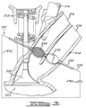
- the heated assembly 310 is for a divided port induction system 314 for a multiple inlet valve internal combustion engine 312.
- the divided port induction system 314 includes a primary inlet runner 318 and a secondary inlet runner 333 to transport the fuel/air mixture into the combustion chamber 320.
- the heated assembly 310 includes a grid 324 extending across the primary inlet runner 318 and mounted to the rotatable throttle shaft 338. Alternatively, the grid 324 could be installed in a fixed position in the primary inlet runner 318.
- the secondary throttle plate 332 is disposed in the secondary inlet runner 333 and rotated by a rotatable shaft 340.
- the secondary inlet runner 333 is opened by an inlet valve 342 to the combustion chamber 320.
- the secondary throttle plate 332 closes the secondary inlet runner 333 during low flow, start, and idle engine operating conditions.
- the primary inlet runner 318 is always open.
- the heated assembly 310 includes electric cables 326 and 328 connected to the grid 324 and a power source such as the battery 330.
- computer control system 341 may be connected to the grid 324 to control the heating of the grid 324 and rotation of the rotatable shaft 338.
- both inlet runners 318 and 333 could have rotational turbulence-generating grids 324 installed, the secondary being a mirror image of the primary.
- the heated assembly 310 operates similar to the heated assembly 10 during cold start/idle conditions.
- FIG. 5 another embodiment 410 of the heated assembly 10, according to the present invention, is illustrated. Like parts of the heated assembly 10 have like reference numerals increased by four hundred (400).
- the heated assembly 410 is used for a dual port induction system 414.
- the heated assembly 410 includes a hollow grid 424 across the primary inlet runner 418.
- the heated assembly 410 also includes a rotatable hollow heat pipe 450 connected to the hollow grid 424 and a stationary hollow heat pipe 451 connected to the pipe 452 and a secondary combustion chamber 452.
- the secondary combustion chamber 452 includes a high pressure fuel air injector 454 having a fuel inlet 456 from a fuel source (not shown) and an air inlet 458 from an air source (not shown) to provide a mixture of air and fuel therein.
- the secondary combustion chamber 452 includes a spark ignitor 460 to ignite the mixture and an exhaust pipe 462 connected to the primary inlet runner 418 upstream of the grid 424.
- the exhaust pipe 462 includes a valve 464 which is connected to and controlled by a controller (not shown).
- the heat pipe 451 is insulated by insulation 466.
- the rotatable hollow heat pipe 450 is connected to the stationary hollow heat pipe 451 by rotatable high temperature and pressure seals 468.
- the primary inlet runner 418 is open during all phases of engine operation.
- the secondary throttle plate 432 is connected to the rotatable hollow heat pipe 450 and is closed during low speed operation.
- the heated assembly 410 chemically heats the grid by heat transfer of exhaust gases from the secondary combustion chamber 452 flowing through the heat pipes 450 and 451 during cold start idle engine operating conditions.
Abstract
Description
Claims (10)
- A heated assembly for vaporisation of fuel in an internal combustion engine comprising:a grid (24) disposed in an inlet runner (18) of the internal combustion engine (12); andmeans (26,28,30) for heating said grid (24) during cold start of the internal combustion engine (12) and vaporising fuel in the inlet runner (18) of the internal combustion engine (12).
- A heated assembly as CLAIMED in claim 1, wherein said heating means comprises electric cables (26,28) connected to said grid (24) and a power source (30) connected to said cables (26,28) to supply power to heat said grid (24).
- A heated assembly as claimed in claim 1, wherein said grid (24) is fixed relative to said inlet runner (18).
- A heated assembly as claimed in claim 3, including a secondary inlet runner (33) having a rotatable throttle plate (32) contained therein.
- A heated assembly as claimed in claim 1, including a throttle plate (132) contained in said inlet runner (118).
- A heated assembly as claimed in claim 5, wherein said throttle plate (132) has an opening (134) and said grid (124) is mounted in said opening (134).
- A heated assembly as claimed in claim 6, wherein said opening (134) has a diameter of approximately one-half a diameter of said inlet runner (118) and being located adjacent a fuel injector (116) mounted in said inlet runner (118).
- A heated assembly as claimed in claim 1, including a rotatable shaft (238), said grid (224) being mounted to said shaft (238).
- A heated assembly as claimed in claim 8, including a secondary inlet runner (233) having a throttle plate (232) contained therein, said throttle plate (232) being mounted to said shaft (238) such that said grid (224) and said throttle plate (232) will open simultaneously.
- A heated assembly for vaporisation of fuel in an internal combustion engine comprising:a grid (124) disposed in an inlet runner (118) of the internal combustion engine;electric cables (126,128) connected to said grid (124) and a power source (130) connected to said cables (126,128) to supply power for heating said grid (124) during cold start of the internal combustion engine and vaporising fuel in the inlet runner (118) of the internal combustion engine;a throttle plate (132) contained in said inlet runner (118); and
wherein said throttle plate (132) has an opening (134) is grid (124) is mounted in said opening (134).
Applications Claiming Priority (2)
| Application Number | Priority Date | Filing Date | Title |
|---|---|---|---|
| US784217 | 1997-01-16 | ||
| US08/784,217 US5813388A (en) | 1997-01-16 | 1997-01-16 | Heated assembly for vaporization of fuel in an internal combustion engine |
Publications (2)
| Publication Number | Publication Date |
|---|---|
| EP0854283A2 true EP0854283A2 (en) | 1998-07-22 |
| EP0854283A3 EP0854283A3 (en) | 1999-03-03 |
Family
ID=25131720
Family Applications (1)
| Application Number | Title | Priority Date | Filing Date |
|---|---|---|---|
| EP97310750A Withdrawn EP0854283A3 (en) | 1997-01-16 | 1997-12-31 | Heated assembly for vaporisation of fuel in an internal combustion engine |
Country Status (2)
| Country | Link |
|---|---|
| US (2) | US5813388A (en) |
| EP (1) | EP0854283A3 (en) |
Cited By (2)
| Publication number | Priority date | Publication date | Assignee | Title |
|---|---|---|---|---|
| WO2002086304A1 (en) * | 2001-04-19 | 2002-10-31 | Roger Kennedy | An induction regulator for an internal combustion engine |
| WO2005061879A1 (en) | 2003-12-24 | 2005-07-07 | Roger Kennedy | An engine efficiency regulator |
Families Citing this family (16)
| Publication number | Priority date | Publication date | Assignee | Title |
|---|---|---|---|---|
| AT5648U1 (en) * | 2001-08-02 | 2002-09-25 | Avl List Gmbh | INTERNAL COMBUSTION ENGINE WITH AT LEAST TWO INLET VALVES PER CYLINDER |
| US6725846B2 (en) | 2001-12-20 | 2004-04-27 | Phillip N. Armstrong | Heated fuel vaporizer block, kit and method |
| US6820864B2 (en) * | 2002-01-15 | 2004-11-23 | Hitachi, Ltd. | Fuel vaporization promoting apparatus and fuel carburetion accelerator |
| US6736376B1 (en) * | 2002-03-19 | 2004-05-18 | Delisle Gilles L. | Anti-detonation fuel delivery system |
| US7249596B2 (en) * | 2002-03-22 | 2007-07-31 | Philip Morris Usa Inc. | Fuel system for an internal combustion engine and method for controlling same |
| US6913004B2 (en) * | 2002-03-22 | 2005-07-05 | Chrysalis Technologies Incorporated | Fuel system for an internal combustion engine and method for controlling same |
| US6820598B2 (en) | 2002-03-22 | 2004-11-23 | Chrysalis Technologies Incorporated | Capillary fuel injector with metering valve for an internal combustion engine |
| US6913005B2 (en) | 2002-03-22 | 2005-07-05 | Chrysalis Technologies Incorporated | System and methodology for purging fuel from a fuel injector during start-up |
| US6871792B2 (en) * | 2002-03-22 | 2005-03-29 | Chrysalis Technologies Incorporated | Apparatus and method for preparing and delivering fuel |
| AU2003223348A1 (en) | 2002-03-22 | 2003-10-13 | Chrysalis Technologies, Inc. | Fuel injector for an internal combustion engine |
| US6779513B2 (en) | 2002-03-22 | 2004-08-24 | Chrysalis Technologies Incorporated | Fuel injector for an internal combustion engine |
| US7032576B2 (en) | 2002-05-10 | 2006-04-25 | Philip Morris Usa Inc. | Capillary heating control and fault detection system and methodology for fuel system in an internal combustion engine |
| US7357124B2 (en) * | 2002-05-10 | 2008-04-15 | Philip Morris Usa Inc. | Multiple capillary fuel injector for an internal combustion engine |
| JP4567687B2 (en) | 2003-10-30 | 2010-10-20 | フィリップ・モリス・ユーエスエイ・インコーポレイテッド | Multi-capillary fuel injector for internal combustion engines |
| US7337768B2 (en) * | 2004-05-07 | 2008-03-04 | Philip Morris Usa Inc. | Multiple capillary fuel injector for an internal combustion engine |
| GB2473279B (en) * | 2009-09-08 | 2015-09-23 | Gm Global Tech Operations Inc | Internal combustion engine and vehicle comprising the internal combustion engine |
Citations (1)
| Publication number | Priority date | Publication date | Assignee | Title |
|---|---|---|---|---|
| US5323753A (en) | 1992-10-19 | 1994-06-28 | Ford Motor Company | Induction system for an internal combustion engine |
Family Cites Families (17)
| Publication number | Priority date | Publication date | Assignee | Title |
|---|---|---|---|---|
| US3747581A (en) * | 1971-02-17 | 1973-07-24 | R Kolb | Method and means for reducing pollutants in exhaust from internal combustion engines |
| DE2309954A1 (en) * | 1973-02-28 | 1974-08-29 | Deutsche Vergaser Gmbh Co Kg | HEATING DEVICE ARRANGED IN A FLOW DUCT |
| US4053544A (en) * | 1974-04-15 | 1977-10-11 | J. C. Moore Research, Inc. | Fuel induction system for internal combustion engines |
| US4023544A (en) * | 1975-02-14 | 1977-05-17 | F. D. Farnum Co. | Precombustion conditioning device for internal combustion engines |
| US4020812A (en) * | 1975-06-18 | 1977-05-03 | Electronic Fuel Saver, Inc. | Fuel atomizing unit |
| US4121543A (en) * | 1976-01-12 | 1978-10-24 | Hicks Jr Jarvis Byron | Precombustion ionization device |
| US4141327A (en) * | 1976-09-09 | 1979-02-27 | Texas Instruments Incorporated | Early fuel evaporation carburetion system |
| US4106454A (en) * | 1976-11-05 | 1978-08-15 | Harvey Jasper | Apparatus for increasing the efficiency of internal combustion engines |
| US4114580A (en) * | 1977-06-20 | 1978-09-19 | Ronald Galen Coats | Distribution rectifier for inlet manifold systems |
| US4187820A (en) * | 1978-10-11 | 1980-02-12 | Heise Richard L | Intake manifold variable atomizing valve |
| US4308845A (en) * | 1979-10-22 | 1982-01-05 | Chrysler Corporation | Early fuel evaporation with bypass |
| US4387676A (en) * | 1980-09-04 | 1983-06-14 | General Motors Corporation | Cold starting system for alcohol fueled engine |
| US4384563A (en) * | 1981-06-26 | 1983-05-24 | Gte Products Corporation | Apparatus for redirection of fuel-air mixture in carburetion system |
| US4491118A (en) * | 1982-09-28 | 1985-01-01 | Wooldridge Bobby M | Fuel mixture method and apparatus employing an electrically heated screen |
| CA1250338A (en) * | 1985-04-01 | 1989-02-21 | Hajimi Nakayama | Air-fuel mixture heating device for use with engine |
| DE3921739C1 (en) * | 1989-07-01 | 1990-11-08 | Daimler-Benz Aktiengesellschaft, 7000 Stuttgart, De | |
| DE4121075A1 (en) * | 1991-06-26 | 1993-01-14 | Pierburg Gmbh | Heating element arrangement in combustion engine inlet manifold - comprises filter for mixt. of air and fuel with provision for electric heating by direct current |
-
1997
- 1997-01-16 US US08/784,217 patent/US5813388A/en not_active Expired - Fee Related
- 1997-12-31 EP EP97310750A patent/EP0854283A3/en not_active Withdrawn
-
1998
- 1998-05-18 US US09/080,679 patent/US6067971A/en not_active Expired - Fee Related
Patent Citations (1)
| Publication number | Priority date | Publication date | Assignee | Title |
|---|---|---|---|---|
| US5323753A (en) | 1992-10-19 | 1994-06-28 | Ford Motor Company | Induction system for an internal combustion engine |
Cited By (6)
| Publication number | Priority date | Publication date | Assignee | Title |
|---|---|---|---|---|
| WO2002086304A1 (en) * | 2001-04-19 | 2002-10-31 | Roger Kennedy | An induction regulator for an internal combustion engine |
| US7171959B2 (en) | 2001-04-19 | 2007-02-06 | Roger Kennedy | Induction regulator for an internal combustion engine |
| AU2002255114B2 (en) * | 2001-04-19 | 2007-03-29 | Roger Kennedy | An induction regulator for an internal combustion engine |
| CN1311154C (en) * | 2001-04-19 | 2007-04-18 | 罗杰·肯尼迪 | Induction regulator for internal combustion engine |
| US7451752B2 (en) | 2001-04-19 | 2008-11-18 | Roger Kennedy | Induction regulator for an internal combustion engine |
| WO2005061879A1 (en) | 2003-12-24 | 2005-07-07 | Roger Kennedy | An engine efficiency regulator |
Also Published As
| Publication number | Publication date |
|---|---|
| US5813388A (en) | 1998-09-29 |
| US6067971A (en) | 2000-05-30 |
| EP0854283A3 (en) | 1999-03-03 |
Similar Documents
| Publication | Publication Date | Title |
|---|---|---|
| US5813388A (en) | Heated assembly for vaporization of fuel in an internal combustion engine | |
| US3941113A (en) | Multicylinder heat engines | |
| CA1141249A (en) | Diesel engine having a subchamber | |
| AU740045B2 (en) | Internal combustion engine fuel management system | |
| WO1983001486A1 (en) | A method of running an internal combustion engine with alternative fuels and an internal combustion engine for alternative fuels | |
| US4438743A (en) | Internal combustion engine | |
| US4445480A (en) | Intake system of internal combustion engine | |
| US5323753A (en) | Induction system for an internal combustion engine | |
| CA2262128A1 (en) | Internal combustion engine having combustion heater | |
| CA1293415C (en) | Internal combustion engine | |
| JP5016748B2 (en) | Internal combustion engine with pressure wave machine | |
| CN103403308A (en) | Sound attenuation device and method for a combustion engine | |
| CA2145435C (en) | Internal combustion engine low temperature starting system | |
| US3741180A (en) | Apparatus for vaporizing a fuel air mixture in the induction system of an combustion engine | |
| US4981114A (en) | Stratified charge internal combustion engine | |
| EP1522697A2 (en) | Method and apparatus for rapid exhaust catalyst light off | |
| US3851634A (en) | Fuel induction system for internal combustion engine | |
| Harada et al. | Nissan NAPS-Z Engine Realizes Better Fuel Economy and Low NOx Emission | |
| GB2218153A (en) | Internal combustion engine | |
| EP0752057A4 (en) | Catalytic method | |
| US1610000A (en) | Vaporizer | |
| US3906914A (en) | Reduction and control of atmospheric pollutants emitted from gasoline powered internal combustion engines | |
| JPH05106519A (en) | Exhaust gas recirculation device for spark ignition engine | |
| US8468822B1 (en) | Charge preparation system for internal combustion engines | |
| KR19980033430A (en) | Engine intake system |
Legal Events
| Date | Code | Title | Description |
|---|---|---|---|
| PUAI | Public reference made under article 153(3) epc to a published international application that has entered the european phase |
Free format text: ORIGINAL CODE: 0009012 |
|
| AK | Designated contracting states |
Kind code of ref document: A2 Designated state(s): DE FR GB |
|
| AX | Request for extension of the european patent |
Free format text: AL;LT;LV;MK;RO;SI |
|
| PUAL | Search report despatched |
Free format text: ORIGINAL CODE: 0009013 |
|
| AK | Designated contracting states |
Kind code of ref document: A3 Designated state(s): AT BE CH DE DK ES FI FR GB GR IE IT LI LU MC NL PT SE |
|
| AX | Request for extension of the european patent |
Free format text: AL;LT;LV;MK;RO;SI |
|
| 17P | Request for examination filed |
Effective date: 19990806 |
|
| AKX | Designation fees paid |
Free format text: DE FR GB |
|
| 17Q | First examination report despatched |
Effective date: 20020212 |
|
| STAA | Information on the status of an ep patent application or granted ep patent |
Free format text: STATUS: THE APPLICATION IS DEEMED TO BE WITHDRAWN |
|
| 18D | Application deemed to be withdrawn |
Effective date: 20020625 |