EP0854027B1 - Insulated modular injection nozzle assembly - Google Patents
Insulated modular injection nozzle assembly Download PDFInfo
- Publication number
- EP0854027B1 EP0854027B1 EP98100855A EP98100855A EP0854027B1 EP 0854027 B1 EP0854027 B1 EP 0854027B1 EP 98100855 A EP98100855 A EP 98100855A EP 98100855 A EP98100855 A EP 98100855A EP 0854027 B1 EP0854027 B1 EP 0854027B1
- Authority
- EP
- European Patent Office
- Prior art keywords
- nozzle
- mold
- gate
- injection nozzle
- gate insert
- Prior art date
- Legal status (The legal status is an assumption and is not a legal conclusion. Google has not performed a legal analysis and makes no representation as to the accuracy of the status listed.)
- Expired - Lifetime
Links
Images





Classifications
-
- B—PERFORMING OPERATIONS; TRANSPORTING
- B29—WORKING OF PLASTICS; WORKING OF SUBSTANCES IN A PLASTIC STATE IN GENERAL
- B29C—SHAPING OR JOINING OF PLASTICS; SHAPING OF MATERIAL IN A PLASTIC STATE, NOT OTHERWISE PROVIDED FOR; AFTER-TREATMENT OF THE SHAPED PRODUCTS, e.g. REPAIRING
- B29C45/00—Injection moulding, i.e. forcing the required volume of moulding material through a nozzle into a closed mould; Apparatus therefor
- B29C45/17—Component parts, details or accessories; Auxiliary operations
- B29C45/26—Moulds
- B29C45/27—Sprue channels ; Runner channels or runner nozzles
- B29C45/2701—Details not specific to hot or cold runner channels
- B29C45/2708—Gates
- B29C45/2711—Gate inserts
-
- B—PERFORMING OPERATIONS; TRANSPORTING
- B29—WORKING OF PLASTICS; WORKING OF SUBSTANCES IN A PLASTIC STATE IN GENERAL
- B29C—SHAPING OR JOINING OF PLASTICS; SHAPING OF MATERIAL IN A PLASTIC STATE, NOT OTHERWISE PROVIDED FOR; AFTER-TREATMENT OF THE SHAPED PRODUCTS, e.g. REPAIRING
- B29C45/00—Injection moulding, i.e. forcing the required volume of moulding material through a nozzle into a closed mould; Apparatus therefor
- B29C45/17—Component parts, details or accessories; Auxiliary operations
- B29C45/26—Moulds
- B29C45/27—Sprue channels ; Runner channels or runner nozzles
-
- B—PERFORMING OPERATIONS; TRANSPORTING
- B29—WORKING OF PLASTICS; WORKING OF SUBSTANCES IN A PLASTIC STATE IN GENERAL
- B29C—SHAPING OR JOINING OF PLASTICS; SHAPING OF MATERIAL IN A PLASTIC STATE, NOT OTHERWISE PROVIDED FOR; AFTER-TREATMENT OF THE SHAPED PRODUCTS, e.g. REPAIRING
- B29C45/00—Injection moulding, i.e. forcing the required volume of moulding material through a nozzle into a closed mould; Apparatus therefor
- B29C45/17—Component parts, details or accessories; Auxiliary operations
- B29C45/26—Moulds
- B29C45/27—Sprue channels ; Runner channels or runner nozzles
- B29C45/278—Nozzle tips
-
- B—PERFORMING OPERATIONS; TRANSPORTING
- B29—WORKING OF PLASTICS; WORKING OF SUBSTANCES IN A PLASTIC STATE IN GENERAL
- B29C—SHAPING OR JOINING OF PLASTICS; SHAPING OF MATERIAL IN A PLASTIC STATE, NOT OTHERWISE PROVIDED FOR; AFTER-TREATMENT OF THE SHAPED PRODUCTS, e.g. REPAIRING
- B29C45/00—Injection moulding, i.e. forcing the required volume of moulding material through a nozzle into a closed mould; Apparatus therefor
- B29C45/17—Component parts, details or accessories; Auxiliary operations
- B29C45/26—Moulds
- B29C45/27—Sprue channels ; Runner channels or runner nozzles
- B29C2045/2766—Heat insulation between nozzle and mould
-
- B—PERFORMING OPERATIONS; TRANSPORTING
- B29—WORKING OF PLASTICS; WORKING OF SUBSTANCES IN A PLASTIC STATE IN GENERAL
- B29C—SHAPING OR JOINING OF PLASTICS; SHAPING OF MATERIAL IN A PLASTIC STATE, NOT OTHERWISE PROVIDED FOR; AFTER-TREATMENT OF THE SHAPED PRODUCTS, e.g. REPAIRING
- B29C45/00—Injection moulding, i.e. forcing the required volume of moulding material through a nozzle into a closed mould; Apparatus therefor
- B29C45/17—Component parts, details or accessories; Auxiliary operations
- B29C45/26—Moulds
- B29C45/27—Sprue channels ; Runner channels or runner nozzles
- B29C45/278—Nozzle tips
- B29C2045/2783—Nozzle tips with a non-axial outlet opening of the melt channel
-
- B—PERFORMING OPERATIONS; TRANSPORTING
- B29—WORKING OF PLASTICS; WORKING OF SUBSTANCES IN A PLASTIC STATE IN GENERAL
- B29C—SHAPING OR JOINING OF PLASTICS; SHAPING OF MATERIAL IN A PLASTIC STATE, NOT OTHERWISE PROVIDED FOR; AFTER-TREATMENT OF THE SHAPED PRODUCTS, e.g. REPAIRING
- B29C45/00—Injection moulding, i.e. forcing the required volume of moulding material through a nozzle into a closed mould; Apparatus therefor
- B29C45/17—Component parts, details or accessories; Auxiliary operations
- B29C45/26—Moulds
- B29C45/27—Sprue channels ; Runner channels or runner nozzles
- B29C45/278—Nozzle tips
- B29C2045/2785—Nozzle tips with high thermal conductivity
Definitions
- the present invention relates to an injection nozzle system. More particularly, the present invention relates to an injection nozzle system comprising modular components, one of which comprises a mold gate insert removably attached to a nozzle tip by a thermal insulating element therebetween, the injection nozzle system being particularly suited for molding relatively large products.
- Injection nozzle systems for hot runner injection systems are well known and include systems such as the SDVG 750 single drop valve gate, SDHT 750 single drop hot sprue and ULTRA ® systems sold by the assignee of the present invention.
- Such injection nozzle systems are constructed to very close tolerances to accommodate the high pressures typically employed in hot runner injection molding and to provide the necessary degree of process control to reduce visible gate vestiges on the molded items, etc.
- avoiding the formation of visible gate vestiges is very much desired within the industry.
- the formation of visible gate vestiges is mitigated by good process control, the high tolerances used in the construction of the nozzle system and by good thermal properties in the nozzle.
- the heater elements in the nozzle system be located as closely as possible to the nozzle tip to ensure rapid and efficient heating of resin in the gate area.
- the mold plates must also be able to provide sufficient cooling to the gate to freeze the resin when the injection portion of the molding cycle is complete.
- US Patent 5,208,052 to Schmidt et al. assigned to the assignee of the present invention, teaches an injection nozzle with a removable nozzle tip made of material with a relatively high thermal conductivity which is surrounded by a removable thermal insulation sleeve made of material with a lower thermal conductivity, which also acts as a seal to intrusion of resin into unwanted regions of the nozzle system.
- US Patent 5,299,928 to Gellert wherein the insulation sleeve is placed between the nozzle tip and the housing of the injection nozzle.
- US Patent 5,569,475 to Adas et al. discloses several types of insulation coating layers that are used in hot runner systems adjacent the mold gate area.
- US Patent US-A-3,113,346 discloses an insulated hot runner assembly in accordance with the preamble of claim 1 wherein a mold gate insert with a mold gate is fitted into the stationary mold plate of the mold.
- a manifold distributes resin via channels to unheated injection nozzles.
- an insulating washer is placed between the mold gate and the nozzle.
- Injection nozzle therefor comprises a radially enlarged portion forming a radially extending abutting surface. When the nozzle tip is axially inserted into said mold gate insert, this radially extending abutting surface is pressed against the insulating washer of said mold gate insert, such that said nozzle tip is maintained adjacent said mold gate.
- Patent Abstracts of Japan, vol. 18, no. 452 (M-1661) & JP-A-06 143358 discloses a system comprising a mold gate insert fixedly embedded into the stationary mold plate. An insulating member is interposed between the tapered nozzle tip and an adjacent tapered surface of said mold gate insert.
- an insulated modular injection nozzle system for use in conjunction with an Injection molding machine, comprising:
- the mold gate insert includes an abutment portion which contacts a mold plate and which is sized to reduce heat transfer between the mold plate and the mold gate insert.
- the thermal insulating member also assists in sealing off the gate area.
- the insulating element assists in the alignment of the mold gate insert relative to the nozzle tip.
- the gate is formed in a gate ring which is removably mounted in the mold gate insert. Further preferred embodiments are defined in the dependent claims.
- Nozzle system 20 is a hot runner injection nozzle system which is located in a mold bore 24 in an injection mold comprising a stationary mold plate 28, which is connected to the injection unit of a molding machine (not shown), and a movable mold plate 32.
- a cavity mold 36 is formed between stationary mold plate 28 and moveable mold plate 32 when the mold is in the closed position, as shown in the Figure.
- FIG. 2 shows an exploded view of some of the components of nozzle system 20.
- nozzle system 20 includes an elongated nozzle housing 40 which is preferably made of material with a relative high thermal conductivity and which defines an inner main melt channel 44 through which pressurized molten resin can pass.
- Nozzle housing 40 includes a connecting portion 48, which in this embodiment is an external set of threads although it is contemplated that other suitable connecting portion configurations can be employed, if desired.
- Nozzle system 20 further includes a removable nozzle tip 52 which includes a first connecting portion 56 to connect to and engage with connecting portion 48 of nozzle housing 40 to form a nozzle assembly.
- connecting portion 48 comprises a set of external threads
- connecting portion 56 comprises a set of complementary internal threads which allow nozzle tip 52 to be screwed into engagement with nozzle housing 40.
- nozzle tip 52 be removably connected to nozzle housing 40
- the present invention can also be employed in systems wherein nozzle tip 52 and nozzle housing 40 are a single element, either a permanent assembly which can not be disassembled or a single integral element, and such configurations are intended to fall within the scope of the present invention.
- Nozzle tip 52 includes a central melt channel 60 which is coaxial with melt channel 44.
- Nozzle tip 52 is also preferably made of a material with a relatively high thermal conductivity, such as copper-based alloys produced, for example, by Ampco.
- nozzle tip 52 is of a type commonly referred to as a divert type and thus comprises at least two angled inner secondary melt channels 64.
- the present invention is not limited to use with divert type nozzle tips and many other nozzle tip types, including univerted, thru-flow, triverted, edge-gating and valve gate tips, amongst others, can be successfully employed with the present invention.
- Nozzle tip 52 further includes a second connecting portion 68 which cooperates with a first connecting portion 72 of an insulating element 76.
- second connecting portion 68 comprises a set of external threads which engage a complementary set of internal threads comprising first connecting portion 72 of insulating element 76.
- insulating element 76 is in the form of a sleeve fabricated from a suitable insulating material which has a relatively low thermal conductivity.
- a suitable insulating material for insulation element 76 is not particularly limited and a variety of several suitable insulating materials will occur to those of skill in the art, examples of which include Titanium and various ceramics.
- First connecting portion 72 of insulating element 76 comprises a set of internal threads which are complementary to the external threads of second connecting portion 68.
- Insulating element 76 also includes a second connecting portion 80 to connect insulating element 76 to a connecting portion 84 of a removable gate insert 88.
- Gate insert 88 includes a mold gate 92 and, as will be apparent, is fabricated from a suitable known material such as well known tooling metals like H-13, P 20 etc.
- second connecting portion 80 of insulating element 76 comprises a set of external threads
- connecting portion 84 of gate insert 88 comprises a set of internal threads complementary thereto.
- the actual geometry and size of mold gate 92 depends upon the particular configuration and size of nozzle tip 52.
- Mold bore 24 terminates with a gate bore 108 that is used to locate and align gate insert 88 with respect to nozzle tip 52.
- gate insert 88 has an outer portion 110 that is larger in diameter than gate bore 108.
- gate insert 88 includes an abutment surface 82 adjacent to lower surface 83 which is of a larger diameter than its throat 87.
- contact between gate insert 88 and mold plate 28 occurs only at abutment surface 82.
- the thermal properties of nozzle system 20 are enhanced as the bulk 85 of gate insert 88 is not in direct thermal contact with mold plate 28 and thus gate 92 can be heated and cooled, as required.
- gate insert 88 avoids the need to machine the mold gate 92 as part of the mold plate 28. This can result in a significant reduction in manufacturing costs and an increase in the accuracy of the machining of gate 92.
- gate insert 88 can be made of different materials than mold plate 28, such as known suitable materials such as tooling metals H-13, 4140 or P 20 and/or materials with a relatively high wear resistance for use with abrasive resins. As replacement of gate 92 merely requires the replacement of gate insert 88, it is also contemplated that maintenance costs will generally be reduced.
- gate insert 88 can be manufactured with lower surface 83 having a desired geometry, such as a concave shape, as shown in Figure 3a, or an inclined surface, such as shown in Figure 3b.
- a desired geometry such as a concave shape, as shown in Figure 3a, or an inclined surface, such as shown in Figure 3b.
- the present invention is not limited to such geometries and other possible geometries will be apparent to those of skill in the art.
- machining of gate insert 88 to obtain a required mold geometry is simpler and less expensive than machining mold plate 28 to achieve that geometry.
- gate 92 can be directly machined into gate insert 88, as shown in Figures 1 and 2, gate 92 can be machined in a separate, removable gate ring 94 as shown in Figure 3c.
- gate ring 94 is mounted in gate insert 88 via an interference fit, with a lower shoulder (not shown) adjacent lower surface 83 to prevent gate ring 94 from being expressed from gate insert 88, or by threads or other suitable mounting means as will occur to those of skill in the art and the use of such a removable gate ring 94 allows further customization of gate material and/or geometry as desired.
- replacement of gate 92 merely requires the replacement of gate ring 94, thus further reducing maintenance costs. This also allows, in the event that conventional hot runner valve gate configurations (not shown) are used, fabrication of gate ring 94 from a wear resistant material that is compatible with the material of the valve gate stem.
- gate insert 88 results in a nozzle system 20 wherein it is easier to clean gate 92 to remove burned resins or other contaminants, to clean the nozzle when resin changes are performed (such as from a first color resin to a second color resin) and to change gate 92 if a different type of nozzle, resin or mold is to be used with nozzle system 20.
- At least one heater element 96 (shown in Figure 1) is located in thermal contact with nozzle housing 40 and nozzle tip 52, preferably as close to gate 92 as possible.
- Heater element 96 can be any suitable heater, such as that described in US Patent 5,411,392 to Von Buren and assigned to the assignee of the present invention.
- pressurized molten plastic resin is injected by nozzle system 20 into cavity mold 36 through mold gate 92 and the pressurized molten plastic resin is maintained in its molten state by heater element 96.
- the injection is topped and a mold cooling system is activated.
- Common mold cooling systems comprise a cooling fluid which is circulated through cooling passages 100 in mold plate 28 when the cooling system is activated and this cooling solidifies the resin in mold gate 92, commonly referred to as 'freezing' the gate, thus permitting the opening of cavity mold 36 for ejection of a solid and cooled molded part (not shown).
- insulating member 76 is employed as shown in Figures 1 and 2 to provide a degree of thermal isolation between gate insert 88 (and thus gate 92) and nozzle tip 52 and nozzle housing 40.
- insulating element 76 provides additional advantages in that it is useful as a locator to assist in the alignment of nozzle tip 52 relative to gate 92, and thus to cavity mold 36, by providing a mechanical connection between nozzle tip 52 and gate insert 88. Further, insulating element 76 acts as a seal to inhibit leakage of pressurized plastic resin into areas within mold bore 24 or gate bore 108.
- nozzle system 20 provides significant advantages over integrally manufactured nozzles and gates, including eased servicing and/or simplified production run changes.
- mold gate inserts are known in the injection molding industry, unlike the prior gate inserts of which the present inventor is aware and which are non-removable as an assembly with the nozzle housing and/or tip (once installed in the mold plate), in the presently preferred embodiments of the invention the mold gate insert is removable with the nozzle and, it is believed that such an insert, in combination with the provision of insulating element 76, results in a particularly advantageous nozzle system.
- nozzle system 20 has a modular construction which can comprise standardized components which have been optimized in terms of materials and/or geometries enabling high quality injection operations to be achieved and yet which can be assembled and serviced with greater simplicity than the prior nozzle systems of which the present inventor is aware. Further, the use of standardized components allows the replacement or exchange of individual components, rather than requiring the replacement of the complete nozzle system as was often the case with the prior systems.
- FIG 4 shows another embodiment of a nozzle system 20' in accordance with the present invention and wherein like components to those of the embodiment of Figures 1 and 2 are identified with like reference numerals and components which differ are identified by reference numerals with a prime (') appended.
- the thermal insulation properties of insulating element 76' are further enhanced by providing a gap 112 between the inner circumference of insulating element 76' and nozzle tip 52'.
- gap 112 While in many circumstances gap 112 will be air filled, it is contemplated that other gases with a lower thermal conductivity may be employed within gap 112 or, for even better insulating ability, a vacuum may be employed within gap 112, if desired. If other gases or a vacuum are employed, a suitable check valve, such as miniature ball check valve 114 shown in Figure 5, or other suitable means of admitting the gas to or creating a vacuum in gap 112 will be provided, as will be apparent to those of skill in the art.
- a suitable check valve such as miniature ball check valve 114 shown in Figure 5, or other suitable means of admitting the gas to or creating a vacuum in gap 112 will be provided, as will be apparent to those of skill in the art.
- an additional improvement in the insulating capabilities of insulating element 76' can be obtained by coating the inner surface of insulating element 76' with a layer of reflective material 116, such as silver or chromium, to reduce heat transfer by radiation.
- second connecting portion 68' of nozzle 52' and first connecting portion 72' are not threaded and insulating element 76' instead includes an inner shoulder portion 117 at its lower end which sealingly engages the lower part of connecting portion 68' and the upper part of connecting portion 68' sealingly engages the upper edge of first connecting portion 72' of insulation element 76'.
- insulation element 76' can be installed by press-fitting or any other suitable technique as will occur to those of skill in the art.
- insulating element 76' may be retained in place via brazing of the upper edge of insulating element 76' to second connecting portion 68' or by complementary threads on the upper and lower parts of connecting portion 68' and 72' or any other suitable retaining technique, as will occur to those of skill in the art. Also, a suitable sealant may be employed in assembling insulating element 76' to nozzle tip 52' if desired.
- second connecting portion 80 of insulating element 76' still engages first connecting portion of gate insert 88, preferably via complementary threads as shown.
- the clearance between the inner surface of insulating element 76' and the outer surface of nozzle tip 52' can preferably range from about 0.1mm to about 10mm.
- FIG. 6 shows another embodiment of a nozzle system 20'' in accordance with the present invention and wherein like components to those of the embodiment of Figures 1 and 2 are identified with like reference numerals and components which differ are identified by reference numerals with two primes ('') appended.
- gate insert 88'' can be removed from the molding area side of mold plate 28'', without the need to remove the balance of nozzle system 20'' from mold plate 28''.
- mold gate bore 108'' has a slightly larger diameter than outer portion 110'' to allow the removal of gate insert 88'' from the molding area without disassembling the nozzle system 20''.
- Gate insert 88'' is maintained in connection with nozzle tip 52 via the connections between second connection portion 68 and first connection portion 72 and between second connection portion 80 and first connection portion 84.
- a suitable tool (not shown) can be employed to engage tool receptacles 122 to rotate gate insert 88'' and disengage gate insert 88'' from nozzle tip 52, allowing gate insert 88'' to be removed from mold bore 24 via gate bore 108''.
- insulating element 76 and/or nozzle tip 52 can also be removed via gate bore 108'' for servicing, replacement or to allow for changes in production requirements and/or processes. In this embodiment in particular, it is also contemplated that insulating element 76 will favorably act to assist in the alignment of gate 92 with end portion 104 of nozzle tip 52.
- heater element 96 can be removed via gate bore 108'' in this embodiment, should it fail or otherwise require replacement. It should be noted that in Figure 6, the relative dimensions of abutment portion 82'' and gate bore 108'' have been somewhat exaggerated for clarity and can be of different relative dimensions.
- gate insert 88'' In order to install and remove gate insert 88'' from mold plate 28'' it is contemplated that two or more tool receptacles 122 will be provided in the outer surface of gate insert 88''.
- tool receptacles 122 are located inside of cavity mold 36, as shown in Figure 6a, some residual plastic sprues 123 may result on the molded articles 125. Should such sprues be unacceptable, a suitable plug 127 may be employed in receptacles 122 to inhibit such sprues from being formed, as shown in Figure 6b.
- a cover plate 126 can be employed to cover receptacles 122 and form the surface of mold cavity 36.
- Plate 126 can be maintained in place by magnets 140, or any other suitable means as will occur to those of skill in the art, and a bore 146 will be provided to allow entry of molten resin into cavity mold 36 from gate 92 resin receptacles 122 will be located outside mold cavity 36.
- gate insert 88'' from the molding area side of mold plate 28'' which is provided by this embodiment has several advantages, including simplified maintenance and servicing of nozzle system 20'' without requiring removal of mold plate 28 from the machine.
- removal of gate insert 88'' from the mold side of mold plate 28'' allows for the simple removal of the bubble of previous color resin which remains in the area in gate insert 88'' between nozzle tip 52 and gate 92.
- this also allows easy changes of gate 92 to accommodate changes in resin parameters during production.
- gate insert 88'' has a gate 92 provided by a gate ring 94, repair or replacement of gate 92 can be accomplished with minimal effort and expense.
- FIG. 7 shows a nozzle system 20''' in accordance with the present invention and wherein like components to those of the embodiment of Figures 1 and 2 are identified with like reference numerals and components which differ are identified by reference numerals with three primes (''') appended.
- insulating element 76''' comprises a layer of suitable insulating material, such as zirconia oxide, which is applied to nozzle tip 52''' as shown. Depending upon the insulating material employed, this layer can be formed by spraying, chemically deposition, sputtering or applied to nozzle tip 52''', by any other suitable means as will occur to those of skill in the art, where it would otherwise directly contact gate insert 88.
- suitable insulating material such as zirconia oxide
- insulating element 76''' can instead be formed on the inner surface of gate insert 88 by similar forming methods. Again depending upon the insulating material employed, the connection of nozzle 52''' to gate insert 88 through second connecting portion 68 of nozzle 52''' and connecting portion 84 can be accomplished via complementary threads, by press fitting or any other suitable means of maintaining this connection as will occur to those of skill in the art.
- insulating element 76''' can comprise the combination of a sleeve, such as that shown in Figures 1 and 2, and a layer of insulating material such as that shown in Figure 7.
- FIG 8 shows a nozzle tip 52'''' in accordance with the present invention and wherein like components to those of the embodiment of Figures 1 and 2 are identified with like reference numerals and components which differ are identified by reference numerals with four primes ('''') appended.
- insulating element 76''''' has been molded in place on nozzle tip 52''''. Specifically, nozzle tip 52'''' is placed into a suitable mold, as an insert, and a suitable moldable composition is injected into the mold about the outer surface of the relevant portion of nozzle tip 52'''' to form insulating element 76''''. Insulating element 76'''' can be molded with a set of external threads 80'''', if desired, to engage the corresponding connection portion of gate insert 88.
- a suitable moldable composition is "salon" (Si - Al - O - N) and at least one additional element selected from the group comprising Ce, La, Dy, Hf and Zr.
- This ceramic material has the desired high strength and low thermal conductivity and is described in "Microstructure and Mechanical Properties of F'Si3Al3O3N5 Ceramics", Kokmeijer et al., Journal of European Ceramic Society, vol. 8, no. 2, 1991, pp. 71-80, the contents of which reference are incorporated herein by reference.
- Figure 8 It is contemplated that the embodiment of Figure 8 will be particularly desirable for systems which require high cavitation, i.e. - several injection nozzles per cavity mold, due to the economical manufacturing costs of nozzle tip 52''''.
- the present invention provides a novel injection nozzle system with improved thermal properties by employing an insulating element and a removable gate insert.
- the modularity of the system can result in simplified assembly and servicing of the system and lower manufacturing costs.
Landscapes
- Engineering & Computer Science (AREA)
- Manufacturing & Machinery (AREA)
- Mechanical Engineering (AREA)
- Moulds For Moulding Plastics Or The Like (AREA)
- Injection Moulding Of Plastics Or The Like (AREA)
- Containers And Packaging Bodies Having A Special Means To Remove Contents (AREA)
Abstract
Description
- The present invention relates to an injection nozzle system. More particularly, the present invention relates to an injection nozzle system comprising modular components, one of which comprises a mold gate insert removably attached to a nozzle tip by a thermal insulating element therebetween, the injection nozzle system being particularly suited for molding relatively large products.
- Injection nozzle systems for hot runner injection systems are well known and include systems such as the SDVG 750 single drop valve gate, SDHT 750 single drop hot sprue and ULTRA® systems sold by the assignee of the present invention. Such injection nozzle systems are constructed to very close tolerances to accommodate the high pressures typically employed in hot runner injection molding and to provide the necessary degree of process control to reduce visible gate vestiges on the molded items, etc.
- In particular, avoiding the formation of visible gate vestiges is very much desired within the industry. As is known to those of skill in the art, the formation of visible gate vestiges is mitigated by good process control, the high tolerances used in the construction of the nozzle system and by good thermal properties in the nozzle. In particular, to obtain acceptable thermal properties, it is desired that the heater elements in the nozzle system be located as closely as possible to the nozzle tip to ensure rapid and efficient heating of resin in the gate area. Of course, the mold plates must also be able to provide sufficient cooling to the gate to freeze the resin when the injection portion of the molding cycle is complete.
- Reference is made in this regard to US Patent 5,046,942 to Gellert which teaches a thermal-gated nozzle wherein a second heating element is located adjacent the mold gate area and embedded inside a two part nozzle tip to provide the desired heating of the nozzle tip.
- One problem which occurs with some prior nozzle systems, such as that taught in Gellert, is that a mechanical contact is present between the nozzle tip and the mold gate area that allows thermal transfer to occur between these two members. Accordingly, undesirable cooling of the nozzle tip occurs, as does undesirable heating of the gate by the heater elements on the nozzle and/or nozzle tip.
- Attempts have been made in the past to mitigate these problems by providing insulation between the gate and the nozzle. For example, US Patent 5,208,052 to Schmidt et al., assigned to the assignee of the present invention, teaches an injection nozzle with a removable nozzle tip made of material with a relatively high thermal conductivity which is surrounded by a removable thermal insulation sleeve made of material with a lower thermal conductivity, which also acts as a seal to intrusion of resin into unwanted regions of the nozzle system. A similar concept is also described in US Patent 5,299,928 to Gellert, wherein the insulation sleeve is placed between the nozzle tip and the housing of the injection nozzle. More recently, US Patent 5,569,475 to Adas et al. discloses several types of insulation coating layers that are used in hot runner systems adjacent the mold gate area.
- However, each of these prior systems, and all others of which the present inventor is aware, suffer from one or more disadvantages and/or drawbacks. For example, the approach shown in Adas has very limited application since the insulation layers taught are very thin and provide little impediment to unwanted heat transfer. Also the layers taught in Adas are not very strong mechanically and are thus susceptible to mechanical failure.
- While the insulation sleeve disclosed by Schmidt in 5,208,052 and the similar sleeve disclosed by Gellert in 5,299,928 are reasonable insulators and are reasonably robust mechanically, these nozzle systems are generally not satisfactory for molding articles from abrasive resins, such as the so-called engineering grade resins of which NORYL® GTX is an example, as such resins damage the mold gate through abrasive wear requiring replacement of the entire mold plate in which the mold gate is formed. Further, these nozzle systems are generally not generally satisfactory for molding articles from heat-sensitive materials, such as crystalline resins of which PA 66 is an example, as such materials require more heat at the gate area than other resins. As the mold gate is embedded in the mold plate in these prior systems and is thus subject to heat loss to the mold plate which is cooled by the mold cooling system, poor thermal performance is obtained and the required heat at the gate cannot reliably be obtained.
- US Patent US-A-3,113,346 discloses an insulated hot runner assembly in accordance with the preamble of claim 1 wherein a mold gate insert with a mold gate is fitted into the stationary mold plate of the mold. A manifold distributes resin via channels to unheated injection nozzles. In order to reduce heat transfer between the mold gate and the injection nozzle, an insulating washer is placed between the mold gate and the nozzle. Injection nozzle therefor comprises a radially enlarged portion forming a radially extending abutting surface. When the nozzle tip is axially inserted into said mold gate insert, this radially extending abutting surface is pressed against the insulating washer of said mold gate insert, such that said nozzle tip is maintained adjacent said mold gate. Patent Abstracts of Japan, vol. 18, no. 452 (M-1661) & JP-A-06 143358 discloses a system comprising a mold gate insert fixedly embedded into the stationary mold plate. An insulating member is interposed between the tapered nozzle tip and an adjacent tapered surface of said mold gate insert.
- It is desired to have a injection nozzle system with good thermal properties and which provides enhanced serviceability and relatively easy assembly and disassembly..
- It is an object of the present invention to provide a novel insulated modular injection nozzle system with a removable mold gate which obviates or mitigates at least one of the disadvantages of the prior art nozzle systems.
- According to a first aspect of the present invention, there is provided an insulated modular injection nozzle system for use in conjunction with an Injection molding machine, comprising:
- a removable mold gate insert having a mold gate therein;
- a nozzle assembly comprising a thermally conductive nozzle housing and a thermally conductive nozzle tip, said nozzle assembly defining at least one inner melt channel to receive, in use, molten resin and to direct said molten resin to said mold gate; and
- an insulating element arranged between said mold gate insert and said conductive nozzle housing such that said nozzle tip is maintained adjacent said mold gate and said insulating element inhibits thermal transfer between the nozzle tip and the mold gate insert;
- Preferably, the mold gate insert includes an abutment portion which contacts a mold plate and which is sized to reduce heat transfer between the mold plate and the mold gate insert. Also preferably, in addition to improving thermal properties of the nozzle system, the thermal insulating member also assists in sealing off the gate area. Also preferably, the insulating element assists in the alignment of the mold gate insert relative to the nozzle tip. Also preferably, the gate is formed in a gate ring which is removably mounted in the mold gate insert. Further preferred embodiments are defined in the dependent claims.
- Preferred embodiments of the present invention will now be described, by way of example only, with reference to the attached Figures, wherein:
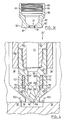
- Figure 1 shows a cross section through an insulated modular injection nozzle system for hot runner injection molding machines in accordance with an embodiment of the present invention;
- Figure 2 shows an exploded cross section of some of the components of Figure 1;
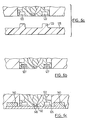
- Figures 3a, 3b and 3c show cross sections of gate inserts for use with a nozzle system in accordance with the present invention;
- Figure 4 shows a cross section through an insulated modular injection nozzle system for hot runner injection molding machines in accordance with another embodiment of the present invention;
- Figure 5 shows a cross section of an insulating element in accordance with an embodiment of the present invention;
- Figure 6 shows a cross section through an insulated modular injection nozzle system for hot runner injection molding machines in accordance with another embodiment of the present invention;
- Figure 6a shows a cross section of the nozzle system of Figure 6 and a part molded therewith;
- Figure 6b shows a cross section of the nozzle system of Figure 6 with plugs installed therein;
- Figure 6c shows a cross section of the nozzle system of Figure 6 with a cover plate installed therein;
- Figure 7 shows a cross section through an insulated modular injection nozzle system for hot runner injection molding machines in accordance with another embodiment of the present invention;
- Figure 8 shows a nozzle tip with a molded insulating element in accordance with another embodiment of the present invention.
- In Figure 1, an insulated modular injection nozzle system in accordance with a first embodiment of the present invention is indicated generally at 20.
Nozzle system 20 is a hot runner injection nozzle system which is located in amold bore 24 in an injection mold comprising astationary mold plate 28, which is connected to the injection unit of a molding machine (not shown), and amovable mold plate 32. Acavity mold 36 is formed betweenstationary mold plate 28 andmoveable mold plate 32 when the mold is in the closed position, as shown in the Figure. - Figure 2 shows an exploded view of some of the components of
nozzle system 20. As can be seen,nozzle system 20 includes anelongated nozzle housing 40 which is preferably made of material with a relative high thermal conductivity and which defines an innermain melt channel 44 through which pressurized molten resin can pass.Nozzle housing 40 includes a connectingportion 48, which in this embodiment is an external set of threads although it is contemplated that other suitable connecting portion configurations can be employed, if desired. -
Nozzle system 20 further includes aremovable nozzle tip 52 which includes a first connectingportion 56 to connect to and engage with connectingportion 48 ofnozzle housing 40 to form a nozzle assembly. As mentioned above, in thisembodiment connecting portion 48 comprises a set of external threads and connectingportion 56 comprises a set of complementary internal threads which allownozzle tip 52 to be screwed into engagement withnozzle housing 40. While it is presently preferred thatnozzle tip 52 be removably connected tonozzle housing 40, the present invention can also be employed in systems whereinnozzle tip 52 andnozzle housing 40 are a single element, either a permanent assembly which can not be disassembled or a single integral element, and such configurations are intended to fall within the scope of the present invention. -
Nozzle tip 52 includes acentral melt channel 60 which is coaxial withmelt channel 44.Nozzle tip 52 is also preferably made of a material with a relatively high thermal conductivity, such as copper-based alloys produced, for example, by Ampco. - As will be apparent to those of skill in the art, in the embodiment of Figures 1 and 2,
nozzle tip 52 is of a type commonly referred to as a divert type and thus comprises at least two angled innersecondary melt channels 64. However, as will also be apparent to those of skill in the art, the present invention is not limited to use with divert type nozzle tips and many other nozzle tip types, including univerted, thru-flow, triverted, edge-gating and valve gate tips, amongst others, can be successfully employed with the present invention. -
Nozzle tip 52 further includes a second connectingportion 68 which cooperates with a first connectingportion 72 of an insulatingelement 76. In this embodiment, second connectingportion 68 comprises a set of external threads which engage a complementary set of internal threads comprising first connectingportion 72 of insulatingelement 76. - In this embodiment of the present invention, insulating
element 76 is in the form of a sleeve fabricated from a suitable insulating material which has a relatively low thermal conductivity. The selection of a suitable insulating material forinsulation element 76 is not particularly limited and a variety of several suitable insulating materials will occur to those of skill in the art, examples of which include Titanium and various ceramics. - First connecting
portion 72 of insulatingelement 76 comprises a set of internal threads which are complementary to the external threads of second connectingportion 68. Insulatingelement 76 also includes a second connectingportion 80 to connect insulatingelement 76 to a connectingportion 84 of aremovable gate insert 88. -
Gate insert 88 includes amold gate 92 and, as will be apparent, is fabricated from a suitable known material such as well known tooling metals like H-13,P 20 etc. Again, in this embodiment second connectingportion 80 of insulatingelement 76 comprises a set of external threads and connectingportion 84 ofgate insert 88 comprises a set of internal threads complementary thereto. The actual geometry and size ofmold gate 92 depends upon the particular configuration and size ofnozzle tip 52. Mold bore 24 terminates with agate bore 108 that is used to locate and aligngate insert 88 with respect tonozzle tip 52. In this particular embodiment,gate insert 88 has anouter portion 110 that is larger in diameter than gate bore 108. - As can be seen in Figure 2,
gate insert 88 includes anabutment surface 82 adjacent tolower surface 83 which is of a larger diameter than itsthroat 87. Thus, as shown in Figure 1, contact betweengate insert 88 andmold plate 28 occurs only atabutment surface 82. As will be apparent to those of skill in the art, by limiting the amount of contact betweengate insert 88 andmold plate 28 and by positioning that limited contact atlower surface 83 adjacent the location ofgate 92, the thermal properties ofnozzle system 20 are enhanced as thebulk 85 ofgate insert 88 is not in direct thermal contact withmold plate 28 and thusgate 92 can be heated and cooled, as required. - It is contemplated that there are several advantages provided by the use of
removable gate insert 88. In particular, use ofgate insert 88 avoids the need to machine themold gate 92 as part of themold plate 28. This can result in a significant reduction in manufacturing costs and an increase in the accuracy of the machining ofgate 92. Also,gate insert 88 can be made of different materials thanmold plate 28, such as known suitable materials such as tooling metals H-13, 4140 orP 20 and/or materials with a relatively high wear resistance for use with abrasive resins. As replacement ofgate 92 merely requires the replacement ofgate insert 88, it is also contemplated that maintenance costs will generally be reduced. - Further, in some circumstances wherein the cavity mold does not have a flat surface,
gate insert 88 can be manufactured withlower surface 83 having a desired geometry, such as a concave shape, as shown in Figure 3a, or an inclined surface, such as shown in Figure 3b. The present invention is not limited to such geometries and other possible geometries will be apparent to those of skill in the art. Clearly, in many circumstance machining ofgate insert 88 to obtain a required mold geometry is simpler and less expensive than machiningmold plate 28 to achieve that geometry. - While
mold gate 92 can be directly machined intogate insert 88, as shown in Figures 1 and 2,gate 92 can be machined in a separate,removable gate ring 94 as shown in Figure 3c. In this alternative,gate ring 94 is mounted ingate insert 88 via an interference fit, with a lower shoulder (not shown) adjacentlower surface 83 to preventgate ring 94 from being expressed fromgate insert 88, or by threads or other suitable mounting means as will occur to those of skill in the art and the use of such aremovable gate ring 94 allows further customization of gate material and/or geometry as desired. In addition, replacement ofgate 92 merely requires the replacement ofgate ring 94, thus further reducing maintenance costs. This also allows, in the event that conventional hot runner valve gate configurations (not shown) are used, fabrication ofgate ring 94 from a wear resistant material that is compatible with the material of the valve gate stem. - In any case, gate insert 88 results in a
nozzle system 20 wherein it is easier to cleangate 92 to remove burned resins or other contaminants, to clean the nozzle when resin changes are performed (such as from a first color resin to a second color resin) and to changegate 92 if a different type of nozzle, resin or mold is to be used withnozzle system 20. - Referring again to Figures 1 and 2, at least one heater element 96 (shown in Figure 1) is located in thermal contact with
nozzle housing 40 andnozzle tip 52, preferably as close togate 92 as possible.Heater element 96 can be any suitable heater, such as that described in US Patent 5,411,392 to Von Buren and assigned to the assignee of the present invention. - In use, pressurized molten plastic resin is injected by
nozzle system 20 intocavity mold 36 throughmold gate 92 and the pressurized molten plastic resin is maintained in its molten state byheater element 96. After thecavity mold 36 has been filled with plastic resin, viamelt channel 44,melt channel 60,secondary melt channels 64 andmold gate 92, the injection is topped and a mold cooling system is activated. Common mold cooling systems comprise a cooling fluid which is circulated throughcooling passages 100 inmold plate 28 when the cooling system is activated and this cooling solidifies the resin inmold gate 92, commonly referred to as 'freezing' the gate, thus permitting the opening ofcavity mold 36 for ejection of a solid and cooled molded part (not shown). - On the next injection cycle, after
cavity mold 36 has been closed, the mold cooling system is deactivated and the resin inmold gate 92 is again converted to the molten state by the heat transferred fromheater element 96 vianozzle tip 52 and injection of molten resin is recommenced. - As mentioned above, it is desirable to place
heater element 96 as close as possible to theend portion 104 of thenozzle tip 52 and thus as close as possible to moldgate 92 to control the melt flow and to thus maintain the size of the residual gate vestige on the molded article at a minimum. As also mentioned above, after the injection of resin is stopped,mold gate 92 must be efficiently cooled by the cooling system to freeze the mold gate and thus inhibit leaking of the resin through themold gate 92 and intomold cavity 36. These contradictory requirements for large and rapid heating and cooling capacities are difficult to achieve, especially within the tight confines of the area aboutgate 92 andend portion 104. To mitigate this difficulty, insulatingmember 76 is employed as shown in Figures 1 and 2 to provide a degree of thermal isolation between gate insert 88 (and thus gate 92) andnozzle tip 52 andnozzle housing 40. - In addition to improving the thermal properties of
nozzle system 20, insulatingelement 76 provides additional advantages in that it is useful as a locator to assist in the alignment ofnozzle tip 52 relative togate 92, and thus tocavity mold 36, by providing a mechanical connection betweennozzle tip 52 andgate insert 88. Further, insulatingelement 76 acts as a seal to inhibit leakage of pressurized plastic resin into areas within mold bore 24 orgate bore 108. - As will be apparent to those of skill in the art, the modular design of
nozzle system 20 provides significant advantages over integrally manufactured nozzles and gates, including eased servicing and/or simplified production run changes. In particular, while mold gate inserts are known in the injection molding industry, unlike the prior gate inserts of which the present inventor is aware and which are non-removable as an assembly with the nozzle housing and/or tip (once installed in the mold plate), in the presently preferred embodiments of the invention the mold gate insert is removable with the nozzle and, it is believed that such an insert, in combination with the provision of insulatingelement 76, results in a particularly advantageous nozzle system. - While the provision of thermal insulation has been disclosed in the US Patent 5,208,052 of Schmidt et al., assigned to the assignee of the present invention, the Schmidt system and the other prior systems of which the present inventor is aware are not modular systems and do not employ gate inserts. Thus, these prior systems are difficult to service and expensive to manufacture. Perhaps more significantly, the non-modular mold gates in the prior art are embedded in the mold plates, resulting in significant thermal transfer from the gate to the mold plate and resulting in generally poor thermal properties for the nozzle system. In contrast, in the present invention contact between
gate insert 88 andmold plate 28 is limited toabutment surface 82, allowinggate insert 88, and thusgate 92, to be maintained at a higher temperature. - As will be apparent from the description above,
nozzle system 20 has a modular construction which can comprise standardized components which have been optimized in terms of materials and/or geometries enabling high quality injection operations to be achieved and yet which can be assembled and serviced with greater simplicity than the prior nozzle systems of which the present inventor is aware. Further, the use of standardized components allows the replacement or exchange of individual components, rather than requiring the replacement of the complete nozzle system as was often the case with the prior systems. - Figure 4 shows another embodiment of a nozzle system 20' in accordance with the present invention and wherein like components to those of the embodiment of Figures 1 and 2 are identified with like reference numerals and components which differ are identified by reference numerals with a prime (') appended. In this embodiment, the thermal insulation properties of insulating element 76' are further enhanced by providing a
gap 112 between the inner circumference of insulating element 76' and nozzle tip 52'. - While in
many circumstances gap 112 will be air filled, it is contemplated that other gases with a lower thermal conductivity may be employed withingap 112 or, for even better insulating ability, a vacuum may be employed withingap 112, if desired. If other gases or a vacuum are employed, a suitable check valve, such as miniatureball check valve 114 shown in Figure 5, or other suitable means of admitting the gas to or creating a vacuum ingap 112 will be provided, as will be apparent to those of skill in the art. In the event that a vacuum is employed ingap 112, an additional improvement in the insulating capabilities of insulating element 76' can be obtained by coating the inner surface of insulating element 76' with a layer ofreflective material 116, such as silver or chromium, to reduce heat transfer by radiation. - When
gap 112 is provided, second connecting portion 68' of nozzle 52' and first connecting portion 72' are not threaded and insulating element 76' instead includes aninner shoulder portion 117 at its lower end which sealingly engages the lower part of connecting portion 68' and the upper part of connecting portion 68' sealingly engages the upper edge of first connecting portion 72' of insulation element 76'. In such a case, insulation element 76' can be installed by press-fitting or any other suitable technique as will occur to those of skill in the art. It is contemplated that insulating element 76' may be retained in place via brazing of the upper edge of insulating element 76' to second connecting portion 68' or by complementary threads on the upper and lower parts of connecting portion 68' and 72' or any other suitable retaining technique, as will occur to those of skill in the art. Also, a suitable sealant may be employed in assembling insulating element 76' to nozzle tip 52' if desired. - As with the embodiment discussed above with respect to Figures 1 and 2, second connecting
portion 80 of insulating element 76' still engages first connecting portion ofgate insert 88, preferably via complementary threads as shown. - It is contemplated that, depending upon the dimensions of nozzle system 20' and the material from which insulating member 76' is fabricated, the clearance between the inner surface of insulating element 76' and the outer surface of nozzle tip 52' (i.e. - the thickness of gap 112) can preferably range from about 0.1mm to about 10mm.
- Figure 6 shows another embodiment of a nozzle system 20'' in accordance with the present invention and wherein like components to those of the embodiment of Figures 1 and 2 are identified with like reference numerals and components which differ are identified by reference numerals with two primes ('') appended. In this embodiment, gate insert 88'' can be removed from the molding area side of mold plate 28'', without the need to remove the balance of nozzle system 20'' from mold plate 28''. Specifically, mold gate bore 108'' has a slightly larger diameter than outer portion 110'' to allow the removal of gate insert 88'' from the molding area without disassembling the nozzle system 20''. Gate insert 88'' is maintained in connection with
nozzle tip 52 via the connections betweensecond connection portion 68 andfirst connection portion 72 and betweensecond connection portion 80 andfirst connection portion 84. - A suitable tool (not shown) can be employed to engage
tool receptacles 122 to rotate gate insert 88'' and disengage gate insert 88'' fromnozzle tip 52, allowing gate insert 88'' to be removed from mold bore 24 via gate bore 108''. If desired, once gate insert 88'' has been removed, insulatingelement 76 and/ornozzle tip 52 can also be removed via gate bore 108'' for servicing, replacement or to allow for changes in production requirements and/or processes. In this embodiment in particular, it is also contemplated that insulatingelement 76 will favorably act to assist in the alignment ofgate 92 withend portion 104 ofnozzle tip 52. Further,heater element 96 can be removed via gate bore 108'' in this embodiment, should it fail or otherwise require replacement. It should be noted that in Figure 6, the relative dimensions of abutment portion 82'' and gate bore 108'' have been somewhat exaggerated for clarity and can be of different relative dimensions. - In order to install and remove gate insert 88'' from mold plate 28'' it is contemplated that two or
more tool receptacles 122 will be provided in the outer surface of gate insert 88''. In the event thattool receptacles 122 are located inside ofcavity mold 36, as shown in Figure 6a, some residualplastic sprues 123 may result on the moldedarticles 125. Should such sprues be unacceptable, asuitable plug 127 may be employed inreceptacles 122 to inhibit such sprues from being formed, as shown in Figure 6b. In other circumstances, such as that shown in the Figure 6c, acover plate 126 can be employed to coverreceptacles 122 and form the surface ofmold cavity 36.Plate 126 can be maintained in place bymagnets 140, or any other suitable means as will occur to those of skill in the art, and abore 146 will be provided to allow entry of molten resin intocavity mold 36 fromgate 92resin receptacles 122 will be located outsidemold cavity 36. - The simple removal and installation of gate insert 88'' from the molding area side of mold plate 28'' which is provided by this embodiment has several advantages, including simplified maintenance and servicing of nozzle system 20'' without requiring removal of
mold plate 28 from the machine. In particular, in molding applications requiring color changes removal of gate insert 88'' from the mold side of mold plate 28'' allows for the simple removal of the bubble of previous color resin which remains in the area in gate insert 88'' betweennozzle tip 52 andgate 92. Further, this also allows easy changes ofgate 92 to accommodate changes in resin parameters during production. Also, if gate insert 88'' has agate 92 provided by agate ring 94, repair or replacement ofgate 92 can be accomplished with minimal effort and expense. - Figure 7 shows a nozzle system 20''' in accordance with the present invention and wherein like components to those of the embodiment of Figures 1 and 2 are identified with like reference numerals and components which differ are identified by reference numerals with three primes (''') appended. In this embodiment, insulating element 76''' comprises a layer of suitable insulating material, such as zirconia oxide, which is applied to nozzle tip 52''' as shown. Depending upon the insulating material employed, this layer can be formed by spraying, chemically deposition, sputtering or applied to nozzle tip 52''', by any other suitable means as will occur to those of skill in the art, where it would otherwise directly contact
gate insert 88. As it will be apparent, insulating element 76''' can instead be formed on the inner surface ofgate insert 88 by similar forming methods. Again depending upon the insulating material employed, the connection of nozzle 52''' to gate insert 88 through second connectingportion 68 of nozzle 52''' and connectingportion 84 can be accomplished via complementary threads, by press fitting or any other suitable means of maintaining this connection as will occur to those of skill in the art. - It is contemplated that the layer of insulating material on nozzle 52''' can be re-applied, from time to time, if necessary. It is also contemplated that insulating element 76''' can comprise the combination of a sleeve, such as that shown in Figures 1 and 2, and a layer of insulating material such as that shown in Figure 7.
- Figure 8 shows a nozzle tip 52'''' in accordance with the present invention and wherein like components to those of the embodiment of Figures 1 and 2 are identified with like reference numerals and components which differ are identified by reference numerals with four primes ('''') appended. In this embodiment, insulating element 76'''' has been molded in place on nozzle tip 52''''. Specifically, nozzle tip 52'''' is placed into a suitable mold, as an insert, and a suitable moldable composition is injected into the mold about the outer surface of the relevant portion of nozzle tip 52'''' to form insulating element 76''''. Insulating element 76'''' can be molded with a set of external threads 80'''', if desired, to engage the corresponding connection portion of
gate insert 88. - An example of a suitable moldable composition is "salon" (Si - Al - O - N) and at least one additional element selected from the group comprising Ce, La, Dy, Hf and Zr. This ceramic material has the desired high strength and low thermal conductivity and is described in "Microstructure and Mechanical Properties of F'Si3Al3O3N5 Ceramics", Kokmeijer et al., Journal of European Ceramic Society, vol. 8, no. 2, 1991, pp. 71-80, the contents of which reference are incorporated herein by reference.
- It is contemplated that the embodiment of Figure 8 will be particularly desirable for systems which require high cavitation, i.e. - several injection nozzles per cavity mold, due to the economical manufacturing costs of nozzle tip 52''''.
- The present invention provides a novel injection nozzle system with improved thermal properties by employing an insulating element and a removable gate insert. In addition, the modularity of the system can result in simplified assembly and servicing of the system and lower manufacturing costs.
- The above-described embodiments of the invention are intended to be examples of the present invention and alterations and modifications may be effected thereto, by those of skill in the art, without departing from the scope of the invention which is defined solely by the claims appended hereto.
Claims (18)
- An insulated modular injection nozzle system (20, 20', 20'', 20''') for use in conjunction with an injection molding machine, the injection nozzle system comprising:a removable mold gate insert (88, 88'', 88''',) having a mold gate (92) therein;a nozzle assembly comprising a thermally conductive nozzle housing (40) and a thermally conductive nozzle tip (52), said nozzle assembly defining at least one inner melt channel (44) to receive, in use, molten resin and to direct said molten resin to said mold gate (92);at least one heater element in thermal contact with said nozzle assembly and operable to maintain said resin in a molten state through said at least one inner melt channel; andan insulating element (76) arranged between said mold gate insert (88) and said conductive nozzle housing (40) such that said nozzle tip (52) is maintained adjacent said mold gate (92) and said insulating element inhibits thermal transfer between the nozzle tip (52) and the mold gate insert (82);the injection nozzle system characterized in that:said mold gate insert is removably connected to said nozzle housing (40) by means of said insulating element, which insulating element (76) is realised by an insulating sleeve having an exterior threaded surface, and said mold gate insert (88) includes an interior thread complementary to the exterior threaded surface of the insulating sleeve to allow the threaded and removable connection of the mold gate insert (88) to the sleeve.
- The injection nozzle system of claim 1 wherein said nozzle tip (52, 52', 52''', 52'''') is removably attached to said nozzle housing (40).
- The injection nozzle system of claim 1 or 2 wherein said sleeve further includes an interior set of threads (72) and said nozzle assembly includes an exterior set of complementary threads (68) to removably connect said sleeve to said nozzle assembly.
- The injection nozzle system of claim 1 wherein said sleeve is press fit into engagement with said nozzle assembly.
- The injection nozzle system of claims 1 to 4 wherein said insulating element (76') further comprises a gap (112) defined between said sleeve and said nozzle assembly.
- The injection nozzle system of claim 5 wherein said gap (112) has a vacuum formed therein.
- The injection nozzle system of claims 5 or 6 wherein at least one interior surface of said gap (112) includes a layer of material (116) reflective to thermal radiation.
- The injection nozzle system of any preceding claim wherein said insulating element (76''') comprises a layer of insulating material formed on said nozzle assembly.
- The injection nozzle system of any preceding claim wherein said insulating element (76''') comprises a layer of insulating material formed on said gate insert.
- The injection nozzle system of any preceding claim wherein said insulating element (76, 76', 76''') is fabricated from Titanium.
- The injection nozzle system of claim 10 wherein said insulating element (76, 76', 76''') is fabricated from zirconia oxide.
- The injection nozzle system of claims 8 or 9 wherein said layer comprises zirconia oxide.
- The injection nozzle system of any preceding claim wherein said mold gate insert (88, 88'', 88''') is fabricated from a material different from that of said mold plate (28, 28'').
- The injection nozzle system of any preceding claim wherein said mold gate (92) is formed by a gate ring (94) removably mounted to said mold gate insert (88).
- The injection nozzle system of any preceding claim wherein said mold gate insert (88'') is removable from the mold area side of a mold plate (28'').
- The injection nozzle system of any preceding claim wherein said insulating element (76, 76', 76''', 76'''') assists in inhibiting ingress of molten resin into unwanted areas within said injection molding machine.
- The injection nozzle system of claim 15 wherein said nozzle tip (52) is removable from said mold area side of said mold plate after said mold gate insert has been removed therefrom.
- The injection nozzle system of any preceding claim wherein said mold gate insert (88, 88'') includes an abutment portion (82, 82'') to engage a mold plate (28, 28''), said abutment portion being located adjacent said mold gate (92) and being sized to mitigate heat transfer between said mold gate (92) and said mold plate (28, 28'').
Applications Claiming Priority (2)
| Application Number | Priority Date | Filing Date | Title |
|---|---|---|---|
| US08/785,841 US5879727A (en) | 1997-01-21 | 1997-01-21 | Insulated modular injection nozzle system |
| US785841 | 1997-01-21 |
Publications (2)
| Publication Number | Publication Date |
|---|---|
| EP0854027A1 EP0854027A1 (en) | 1998-07-22 |
| EP0854027B1 true EP0854027B1 (en) | 2007-04-25 |
Family
ID=25136786
Family Applications (1)
| Application Number | Title | Priority Date | Filing Date |
|---|---|---|---|
| EP98100855A Expired - Lifetime EP0854027B1 (en) | 1997-01-21 | 1998-01-19 | Insulated modular injection nozzle assembly |
Country Status (6)
| Country | Link |
|---|---|
| US (1) | US5879727A (en) |
| EP (1) | EP0854027B1 (en) |
| AT (1) | ATE360515T1 (en) |
| CA (1) | CA2227085C (en) |
| DE (1) | DE69837631T2 (en) |
| ES (1) | ES2284189T3 (en) |
Families Citing this family (83)
| Publication number | Priority date | Publication date | Assignee | Title |
|---|---|---|---|---|
| US5820900A (en) * | 1996-08-21 | 1998-10-13 | Mcgrevy; Alan N. | Heating device for an injection mold apparatus |
| US6352426B1 (en) | 1998-03-19 | 2002-03-05 | Advanced Plastics Technologies, Ltd. | Mold for injection molding multilayer preforms |
| US6074195A (en) * | 1998-12-08 | 2000-06-13 | Fast Heat, Inc. | Hot runner nozzle with laminar flow pin point tip |
| CA2262175C (en) * | 1999-02-16 | 2008-02-12 | Mold-Masters Limited | Injection molding apparatus with removable nozzle seal |
| US6533571B2 (en) * | 1999-03-19 | 2003-03-18 | Husky Injection Molding Systems, Ltd | Injection nozzle insulator assembly |
| CA2286953A1 (en) * | 1999-10-18 | 2001-04-18 | Helen Zhuang | Injection nozzle system |
| US6264460B1 (en) | 1999-12-09 | 2001-07-24 | Pechiney Emballage Flexible Europe | Injection gate insulating and cooling apparatus |
| US6769901B2 (en) * | 2000-04-12 | 2004-08-03 | Mold-Masters Limited | Injection nozzle system for an injection molding machine |
| US6394785B1 (en) * | 2000-11-20 | 2002-05-28 | Top Grade Molds Ltd. | Nozzle for injection mold |
| CA2332061A1 (en) | 2001-01-23 | 2002-07-23 | Mold-Masters Limited | Nozzle end for multiple tipped injection molding nozzle |
| CA2358148A1 (en) * | 2001-10-03 | 2003-04-03 | Mold-Masters Limited | A nozzle |
| CA2358187A1 (en) * | 2001-10-03 | 2003-04-03 | Mold-Masters Limited | Nozzle seal |
| DE10246701B4 (en) * | 2001-10-05 | 2017-01-12 | Mold-Masters (2007) Limited | Injection molding device and nozzle with a gap seal between nozzle components |
| US6962492B2 (en) * | 2001-10-05 | 2005-11-08 | Mold-Masters Limited | Gap seal between nozzle components |
| ITTO20011214A1 (en) * | 2001-12-21 | 2003-06-21 | Incos Spa | INJECTOR NOZZLE FOR INJECTION MOLDING EQUIPMENT OF PLASTIC MATERIALS. |
| AU2003206525A1 (en) * | 2002-02-21 | 2003-09-09 | Mold-Masters Limited | A valve pin guide for a valve-gated nozzle |
| US7128566B2 (en) * | 2002-02-21 | 2006-10-31 | Mold-Masters Limited | Valve pin guiding tip for a nozzle |
| DE10392533B4 (en) * | 2002-04-12 | 2014-07-03 | Mold-Masters (2007) Limited | Injection molding device with a mold gate insert with thermal lock |
| JP2005534534A (en) * | 2002-07-30 | 2005-11-17 | モールド‐マスターズ、リミテッド | Valve pin guide and centering system for injection molding equipment |
| US6780003B2 (en) * | 2002-08-02 | 2004-08-24 | Mold-Masters Limited | Removable heater for a hot runner nozzle |
| US6726467B1 (en) * | 2002-10-16 | 2004-04-27 | R&D Tool & Engineering Co. | Injection molding nozzle |
| CA2505697C (en) * | 2002-11-08 | 2013-10-22 | Advanced Plastics Technologies Ltd. | Injection mold having a wear resistant portion and a high heat transfer portion and a method of forming a preform |
| US6609902B1 (en) | 2002-11-12 | 2003-08-26 | Husky Injection Molding Systems Ltd. | Injection molding nozzle |
| CA2450411C (en) * | 2002-11-21 | 2012-01-03 | Mold-Masters Limited | Hot runner nozzle with a tip, a tip surrounding piece and an alignment piece |
| US20050181090A1 (en) * | 2002-12-06 | 2005-08-18 | Mold-Masters Limited | Injection molding nozzle with embedded and removable heaters |
| DE10356937A1 (en) * | 2002-12-09 | 2004-07-15 | Mold-Masters Ltd., Georgetown | Nozzle for injection molding apparatus comprises nozzle body, heater, tip, tip surrounding piece, and seal piece |
| CA2453170C (en) * | 2002-12-20 | 2012-02-21 | Mold-Masters Limited | Lateral gating injection molding apparatus |
| US7175416B2 (en) * | 2003-03-31 | 2007-02-13 | Thermal Wave Molding Corp. | Injection molding nozzle structured for cooling at extreme tip |
| DE602004025755D1 (en) * | 2003-04-07 | 2010-04-08 | Mold Masters 2007 Ltd | Hot runner nozzle with enamel seal |
| US7143496B2 (en) * | 2003-05-08 | 2006-12-05 | Mold-Masters Limited | Hot runner nozzle with removable tip and tip retainer |
| US7131832B2 (en) * | 2003-05-08 | 2006-11-07 | Mold-Masters Limited | Transfer seal for a removable nozzle tip of an injection molding apparatus |
| US20040234646A1 (en) * | 2003-05-16 | 2004-11-25 | Salvatore Benenati | Tip jacket for plastic injection molding nozzles |
| US7413131B2 (en) * | 2003-08-25 | 2008-08-19 | Husky Injection Molding Systems Ltd. | Hot runner system components of two materials and method of manufacture |
| US7160100B2 (en) | 2004-01-06 | 2007-01-09 | Mold-Masters Limited | Injection molding apparatus having an elongated nozzle incorporating multiple nozzle bodies in tandem |
| DE102004009799B4 (en) * | 2004-02-28 | 2006-03-23 | Incoe International, Inc. | Tool insert for the cutting of a hot runner nozzle for an injection molding machine |
| CA2482254A1 (en) * | 2004-04-07 | 2005-10-07 | Mold-Masters Limited | Modular injection nozzle having a thermal barrier |
| ATE424288T1 (en) | 2004-04-16 | 2009-03-15 | Advanced Plastics Technologies | PREFORM AND METHOD FOR PRODUCING THE PREFORM AND A BOTTLE |
| US20060065992A1 (en) * | 2004-04-16 | 2006-03-30 | Hutchinson Gerald A | Mono and multi-layer articles and compression methods of making the same |
| US7544056B2 (en) | 2004-06-02 | 2009-06-09 | Mold-Masters (2007) Limited | Valve-gated injection molding nozzle having an annular flow |
| DE602005017444D1 (en) * | 2004-06-02 | 2009-12-17 | Mold Masters 2007 Ltd | Closure nozzle device for injection molding with an annular flow |
| US7344372B2 (en) * | 2004-06-02 | 2008-03-18 | Mold-Masters (2007) Limited | Injection molding nozzle having an annular flow tip |
| US7303387B2 (en) * | 2004-06-10 | 2007-12-04 | Advanced Plastics Technologies Luxembourg S.A. | System for controlling mold temperatures |
| US7217120B2 (en) * | 2004-06-16 | 2007-05-15 | V-Tek Molding Technologies Inc. | Hot runner nozzle |
| US7458804B2 (en) * | 2004-11-04 | 2008-12-02 | Plastic Engineering & Technical Services, Inc. | Injection molding drop tip |
| ITTO20050302A1 (en) * | 2005-05-05 | 2006-11-06 | Incos Spa | INJECTOR NOZZLE TERMINAL FOR PLASTIC INJECTION MOLDING EQUIPMENT |
| MX2008002479A (en) * | 2005-08-30 | 2008-04-07 | Advanced Plastics Technologies | METHODS AND SYSTEMS FOR CONTROLLING MOLD TEMPERATURES. |
| US7370417B2 (en) * | 2005-12-09 | 2008-05-13 | Mold-Masters (2007) Limited | Method of installing a mold gate insert in an injection molding apparatus |
| US7704069B2 (en) * | 2005-12-20 | 2010-04-27 | R&D Tool & Engineering Co. | Injection molding apparatus having swiveling nozzles |
| AU2007206634A1 (en) * | 2006-01-20 | 2007-07-26 | The Procter & Gamble Company | Modular mold system for production of product families |
| US7467940B2 (en) | 2006-10-20 | 2008-12-23 | Husky Injection Molding Systems Ltd. | System and Method for Joining Non-Compatible Components |
| US8887296B2 (en) * | 2006-12-12 | 2014-11-11 | The Boeing Company | Method and system for object-based multi-level security in a service oriented architecture |
| US7494336B2 (en) | 2007-05-03 | 2009-02-24 | Husky Injection Molding Systems Ltd. | Nanocrystalline hot runner nozzle and nozzle tip |
| US20080292745A1 (en) * | 2007-05-23 | 2008-11-27 | Husky Injection Molding Systems Ltd. | Mold Structure and Method of Manufacture Thereof |
| WO2008152872A1 (en) * | 2007-06-14 | 2008-12-18 | Konica Minolta Opto, Inc. | Injection nozzle and molding apparatus |
| US7771189B2 (en) | 2008-03-03 | 2010-08-10 | R&D Tool & Engineering Co. | Injection molding apparatus with replaceable gate insert |
| DE202008007918U1 (en) * | 2008-06-16 | 2009-11-19 | Günther Heisskanaltechnik Gmbh | Injection molding nozzle for an injection mold |
| US7922479B2 (en) * | 2008-06-30 | 2011-04-12 | Caterpillar Inc. | Modular injection molding hot runner system |
| US7993125B2 (en) * | 2008-06-30 | 2011-08-09 | Caterpillar Inc. | Repair tool for injection molding hot runner system |
| US7972132B2 (en) * | 2008-10-10 | 2011-07-05 | Mold-Masters (2007) Ltd | Injection molding valve gated hot runner nozzle |
| US7918663B2 (en) * | 2009-03-05 | 2011-04-05 | Mold-Masters (2007) Limited | Injection molding nozzle wedge seal |
| FR2948057A1 (en) * | 2009-07-16 | 2011-01-21 | Airbus Operations Sas | IMPROVED INTERFACE DEVICE FOR INJECTION |
| DE102010056073B4 (en) | 2010-12-23 | 2022-02-17 | Otto Männer Innovation GmbH | hot runner nozzle |
| WO2012109117A2 (en) * | 2011-02-09 | 2012-08-16 | Husky Injection Molding Systems Ltd | Mold-tool system having heat-transfer obstruction |
| US8899964B2 (en) | 2012-03-16 | 2014-12-02 | Mold-Masters (2007) Limited | Edge-gated injection molding apparatus |
| DE102012104291B4 (en) * | 2012-05-16 | 2014-07-10 | Günther Heisskanaltechnik Gmbh | Nozzle mouthpiece for an injection molding nozzle, injection molding nozzle and injection mold |
| WO2014050768A1 (en) * | 2012-09-27 | 2014-04-03 | オリンパス株式会社 | Hot runner forming device and hot runner nozzle |
| US20140105511A1 (en) * | 2012-10-11 | 2014-04-17 | Macaulay-Brown, Inc. | Matched representation space method for numerically encoding data |
| US9162384B2 (en) * | 2013-03-22 | 2015-10-20 | Otto Männer Innovation GmbH | Injection nozzle with multi-piece tip portion |
| US9381691B2 (en) | 2013-06-25 | 2016-07-05 | Plastic Engineering & Technical Services, Inc. | Pressure resistant drop tip nozzle for injection molding |
| DE102014210332A1 (en) * | 2014-06-02 | 2015-12-03 | AWETIS Engineering + Manufacturing GmbH | Injection nozzle for introducing sprayed material into an injection mold |
| PL3157351T3 (en) * | 2014-06-20 | 2019-11-29 | Live Tech S R L | Injection molding system for a fat-containing product |
| US9272453B1 (en) * | 2014-08-29 | 2016-03-01 | Husky Injection Molding Systems Ltd. | Hot runner with removable gate pad |
| ITUB20153137A1 (en) * | 2015-08-14 | 2017-02-14 | Inglass Spa | NOZZLE TERMINAL FOR PLASTIC INJECTION MOLDING INJECTORS OF PLASTIC MATERIALS |
| CA3018149C (en) * | 2016-03-18 | 2020-09-22 | Honda Motor Co., Ltd. | Injection molding machine nozzle |
| CN107650337A (en) * | 2016-07-26 | 2018-02-02 | 柳道万和(苏州)热流道系统有限公司 | Nozzle assembly and hot flow path adapted to injection system for hot flow path adapted to injection system |
| DE102017107443A1 (en) * | 2017-04-06 | 2018-10-11 | Günther Heisskanaltechnik Gmbh | Insert for use in an injection molding nozzle and injection molding nozzle with such an insert |
| CN108973032A (en) * | 2017-06-02 | 2018-12-11 | 柳道万和(苏州)热流道系统有限公司 | Hot mouth component and hot runner system with it |
| US12246476B2 (en) * | 2018-06-25 | 2025-03-11 | Husky Injection Molding Systems Ltd. | Nozzle with removable nozzle tip configured for improved heating |
| US20200070393A1 (en) * | 2018-09-04 | 2020-03-05 | Chung Hsien Lin | Movable Needle Valve of Hot-Runner Mold |
| CN110722746A (en) * | 2019-10-29 | 2020-01-24 | 柳道万和(苏州)热流道系统有限公司 | Hot nozzle assembly and hot runner system |
| CN112035933B (en) * | 2020-09-03 | 2022-02-22 | 西北工业大学 | Solid rocket engine jet pipe thermal structure coupling analysis method considering structural clearance |
| IT202000021799A1 (en) * | 2020-09-16 | 2022-03-16 | Inglass Spa | HOT ROOM INSERT |
| EP4403331B1 (en) | 2023-01-17 | 2025-03-26 | Witosa GmbH | Insulating body and injection moulding tool comprising such an insulating body |
Family Cites Families (12)
| Publication number | Priority date | Publication date | Assignee | Title |
|---|---|---|---|---|
| US3113346A (en) * | 1962-03-22 | 1963-12-10 | Bois Plastic Products Inc Du | Nozzle arrangement for hot runner plastic molds |
| CH551273A (en) * | 1972-09-06 | 1974-07-15 | Furrer Edmond | Insulated block - for connecting extruder or injection machine to the injection mould |
| US4266723A (en) * | 1979-11-02 | 1981-05-12 | Incoe Corporation | Nozzle for injection molding machines |
| DE3337803C2 (en) * | 1983-10-18 | 1986-07-10 | Herbert Dipl.-Ing. 3559 Allendorf Günther | Hot runner system for injection molding devices |
| US5028227A (en) * | 1988-10-31 | 1991-07-02 | Mold-Masters Limited | Injection molding nozzle with replaceable gate insert |
| CA2030286C (en) * | 1990-11-19 | 2000-11-21 | Jobst Ulrich Gellert | Injection molding nozzle having tapered heating element adjacent the bore |
| US5208052A (en) * | 1991-11-18 | 1993-05-04 | Husky Injection Molding Systems Ltd. | Hot runner nozzle assembly |
| JP3082476B2 (en) * | 1992-11-05 | 2000-08-28 | 三菱マテリアル株式会社 | Injection mold |
| US5569475A (en) * | 1993-06-10 | 1996-10-29 | D-M-E Company | Insulator for thermoplastic molding nozzle assembly |
| US5299928A (en) * | 1993-07-26 | 1994-04-05 | Gellert Jobst U | Two-piece injection molding nozzle seal |
| US5513976A (en) * | 1994-04-13 | 1996-05-07 | Caco Pacific Corporation | Nozzle for heating and passing a fluid into a mold |
| US5443381A (en) * | 1994-07-18 | 1995-08-22 | Gellert; Jobst U. | Injection molding one-piece insert having cooling chamber with radial rib portions |
-
1997
- 1997-01-21 US US08/785,841 patent/US5879727A/en not_active Expired - Fee Related
-
1998
- 1998-01-15 CA CA002227085A patent/CA2227085C/en not_active Expired - Fee Related
- 1998-01-19 ES ES98100855T patent/ES2284189T3/en not_active Expired - Lifetime
- 1998-01-19 AT AT98100855T patent/ATE360515T1/en not_active IP Right Cessation
- 1998-01-19 DE DE69837631T patent/DE69837631T2/en not_active Expired - Fee Related
- 1998-01-19 EP EP98100855A patent/EP0854027B1/en not_active Expired - Lifetime
Also Published As
| Publication number | Publication date |
|---|---|
| US5879727A (en) | 1999-03-09 |
| DE69837631T2 (en) | 2008-02-14 |
| ATE360515T1 (en) | 2007-05-15 |
| DE69837631D1 (en) | 2007-06-06 |
| EP0854027A1 (en) | 1998-07-22 |
| ES2284189T3 (en) | 2007-11-01 |
| CA2227085C (en) | 2006-12-12 |
| CA2227085A1 (en) | 1998-07-21 |
Similar Documents
| Publication | Publication Date | Title |
|---|---|---|
| US5879727A (en) | Insulated modular injection nozzle system | |
| US7025586B2 (en) | Valve pin guidance and alignment system for an injection molding apparatus | |
| EP0153554B1 (en) | Injection molding valve gated system | |
| EP1343619B1 (en) | Nozzle for injection mold | |
| EP0885707B1 (en) | Injection molding nozzle assembly | |
| US4981431A (en) | Injection molding system with flanged insulating gate seal | |
| EP0405007B1 (en) | Injection molding system having dual feed bushing seated in manifold | |
| EP2174767B1 (en) | Injection molding valve gated hot runner nozzle | |
| CA1252971A (en) | Mechanism for valve gated injection molding with resilient retaining ring | |
| CA2030287C (en) | Injection molding apparatus having separate heating element in the cavity forming insert | |
| EP0936047B1 (en) | Injection molding method, injection mold, and valve gate device | |
| WO1995005276A1 (en) | Improved hot runner injection molding system | |
| EP1436133B1 (en) | Gap seal between a nozzle and a mold component in a hot-runner assembly for an injection molding apparatus | |
| EP0021273B1 (en) | Injection mechanism for molding plastics | |
| US20030180412A1 (en) | Nozzle cap | |
| JPS60897B2 (en) | injection molding system | |
| EP0496284A2 (en) | Injection molding apparatus with integral cooling in a forward portion of the nozzle | |
| EP1475211B1 (en) | Transfer seal for a removeable nozzle tip of an injection molding apparatus | |
| EP0960713B1 (en) | Injection molding apparatus having nozzles with elongated mounting flanges | |
| EP0633118B1 (en) | Two-piece injection molding nozzle seal | |
| US20040043102A1 (en) | Alignment collar for a nozzle | |
| CA3000911A1 (en) | Insert for use in an injection molding nozzle and injection molding nozzle with such an insert | |
| EP0346900B1 (en) | Injection molding system with insertable insulating ring | |
| US7370417B2 (en) | Method of installing a mold gate insert in an injection molding apparatus | |
| CA1314370C (en) | Injection molding system having fluid cooled inserts |
Legal Events
| Date | Code | Title | Description |
|---|---|---|---|
| PUAI | Public reference made under article 153(3) epc to a published international application that has entered the european phase |
Free format text: ORIGINAL CODE: 0009012 |
|
| AK | Designated contracting states |
Kind code of ref document: A1 Designated state(s): AT CH DE ES FR GB IT LI NL SE |
|
| AX | Request for extension of the european patent |
Free format text: AL;LT;LV;MK;RO;SI |
|
| 17P | Request for examination filed |
Effective date: 19990115 |
|
| AKX | Designation fees paid |
Free format text: AT CH DE ES FR GB IT LI NL SE |
|
| RBV | Designated contracting states (corrected) |
Designated state(s): AT CH DE ES FR GB IT LI NL SE |
|
| 17Q | First examination report despatched |
Effective date: 20001110 |
|
| APBR | Date of receipt of statement of grounds of appeal recorded |
Free format text: ORIGINAL CODE: EPIDOSNNOA3E |
|
| APBT | Appeal procedure closed |
Free format text: ORIGINAL CODE: EPIDOSNNOA9E |
|
| APAF | Appeal reference modified |
Free format text: ORIGINAL CODE: EPIDOSCREFNE |
|
| GRAP | Despatch of communication of intention to grant a patent |
Free format text: ORIGINAL CODE: EPIDOSNIGR1 |
|
| GRAS | Grant fee paid |
Free format text: ORIGINAL CODE: EPIDOSNIGR3 |
|
| GRAA | (expected) grant |
Free format text: ORIGINAL CODE: 0009210 |
|
| AK | Designated contracting states |
Kind code of ref document: B1 Designated state(s): AT CH DE ES FR GB IT LI NL SE |
|
| REG | Reference to a national code |
Ref country code: GB Ref legal event code: FG4D |
|
| REG | Reference to a national code |
Ref country code: CH Ref legal event code: EP |
|
| REF | Corresponds to: |
Ref document number: 69837631 Country of ref document: DE Date of ref document: 20070606 Kind code of ref document: P |
|
| PG25 | Lapsed in a contracting state [announced via postgrant information from national office to epo] |
Ref country code: SE Free format text: LAPSE BECAUSE OF FAILURE TO SUBMIT A TRANSLATION OF THE DESCRIPTION OR TO PAY THE FEE WITHIN THE PRESCRIBED TIME-LIMIT Effective date: 20070725 |
|
| REG | Reference to a national code |
Ref country code: CH Ref legal event code: NV Representative=s name: BOVARD AG PATENTANWAELTE |
|
| ET | Fr: translation filed | ||
| NLV1 | Nl: lapsed or annulled due to failure to fulfill the requirements of art. 29p and 29m of the patents act | ||
| REG | Reference to a national code |
Ref country code: ES Ref legal event code: FG2A Ref document number: 2284189 Country of ref document: ES Kind code of ref document: T3 |
|
| PG25 | Lapsed in a contracting state [announced via postgrant information from national office to epo] |
Ref country code: NL Free format text: LAPSE BECAUSE OF FAILURE TO SUBMIT A TRANSLATION OF THE DESCRIPTION OR TO PAY THE FEE WITHIN THE PRESCRIBED TIME-LIMIT Effective date: 20070425 |
|
| PGFP | Annual fee paid to national office [announced via postgrant information from national office to epo] |
Ref country code: CH Payment date: 20071130 Year of fee payment: 11 |
|
| PLBE | No opposition filed within time limit |
Free format text: ORIGINAL CODE: 0009261 |
|
| STAA | Information on the status of an ep patent application or granted ep patent |
Free format text: STATUS: NO OPPOSITION FILED WITHIN TIME LIMIT |
|
| 26N | No opposition filed |
Effective date: 20080128 |
|
| PGFP | Annual fee paid to national office [announced via postgrant information from national office to epo] |
Ref country code: GB Payment date: 20071130 Year of fee payment: 11 Ref country code: FR Payment date: 20071130 Year of fee payment: 11 Ref country code: ES Payment date: 20071129 Year of fee payment: 11 |
|
| PGFP | Annual fee paid to national office [announced via postgrant information from national office to epo] |
Ref country code: IT Payment date: 20080107 Year of fee payment: 11 Ref country code: DE Payment date: 20071129 Year of fee payment: 11 |
|
| PGFP | Annual fee paid to national office [announced via postgrant information from national office to epo] |
Ref country code: AT Payment date: 20071129 Year of fee payment: 11 |
|
| REG | Reference to a national code |
Ref country code: CH Ref legal event code: PL |
|
| GBPC | Gb: european patent ceased through non-payment of renewal fee |
Effective date: 20090119 |
|
| PG25 | Lapsed in a contracting state [announced via postgrant information from national office to epo] |
Ref country code: LI Free format text: LAPSE BECAUSE OF NON-PAYMENT OF DUE FEES Effective date: 20090131 Ref country code: DE Free format text: LAPSE BECAUSE OF NON-PAYMENT OF DUE FEES Effective date: 20090801 Ref country code: CH Free format text: LAPSE BECAUSE OF NON-PAYMENT OF DUE FEES Effective date: 20090131 Ref country code: AT Free format text: LAPSE BECAUSE OF NON-PAYMENT OF DUE FEES Effective date: 20090119 |
|
| REG | Reference to a national code |
Ref country code: FR Ref legal event code: ST Effective date: 20091030 |
|
| PG25 | Lapsed in a contracting state [announced via postgrant information from national office to epo] |
Ref country code: GB Free format text: LAPSE BECAUSE OF NON-PAYMENT OF DUE FEES Effective date: 20090119 |
|
| REG | Reference to a national code |
Ref country code: ES Ref legal event code: FD2A Effective date: 20090120 |
|
| PG25 | Lapsed in a contracting state [announced via postgrant information from national office to epo] |
Ref country code: FR Free format text: LAPSE BECAUSE OF NON-PAYMENT OF DUE FEES Effective date: 20090202 Ref country code: ES Free format text: LAPSE BECAUSE OF NON-PAYMENT OF DUE FEES Effective date: 20090120 |
|
| PG25 | Lapsed in a contracting state [announced via postgrant information from national office to epo] |
Ref country code: IT Free format text: LAPSE BECAUSE OF NON-PAYMENT OF DUE FEES Effective date: 20090119 |