EP0853714B1 - Power drive for a movable closure with ball nut drive screw - Google Patents
Power drive for a movable closure with ball nut drive screw Download PDFInfo
- Publication number
- EP0853714B1 EP0853714B1 EP96945213A EP96945213A EP0853714B1 EP 0853714 B1 EP0853714 B1 EP 0853714B1 EP 96945213 A EP96945213 A EP 96945213A EP 96945213 A EP96945213 A EP 96945213A EP 0853714 B1 EP0853714 B1 EP 0853714B1
- Authority
- EP
- European Patent Office
- Prior art keywords
- ball nut
- drive
- drive member
- power drive
- door
- Prior art date
- Legal status (The legal status is an assumption and is not a legal conclusion. Google has not performed a legal analysis and makes no representation as to the accuracy of the status listed.)
- Expired - Lifetime
Links
- 230000004888 barrier function Effects 0.000 claims abstract description 13
- 230000003134 recirculating effect Effects 0.000 claims abstract description 6
- 230000033001 locomotion Effects 0.000 claims description 32
- 230000002441 reversible effect Effects 0.000 claims description 12
- 150000001875 compounds Chemical class 0.000 abstract description 8
- 230000004044 response Effects 0.000 description 7
- 230000008878 coupling Effects 0.000 description 5
- 238000010168 coupling process Methods 0.000 description 5
- 238000005859 coupling reaction Methods 0.000 description 5
- 238000010276 construction Methods 0.000 description 4
- 230000007246 mechanism Effects 0.000 description 4
- 230000000712 assembly Effects 0.000 description 2
- 238000000429 assembly Methods 0.000 description 2
- 238000012986 modification Methods 0.000 description 2
- 230000004048 modification Effects 0.000 description 2
- BQCADISMDOOEFD-UHFFFAOYSA-N Silver Chemical compound [Ag] BQCADISMDOOEFD-UHFFFAOYSA-N 0.000 description 1
- 230000001133 acceleration Effects 0.000 description 1
- 238000013459 approach Methods 0.000 description 1
- 230000005540 biological transmission Effects 0.000 description 1
- 238000006243 chemical reaction Methods 0.000 description 1
- 238000004891 communication Methods 0.000 description 1
- 238000002788 crimping Methods 0.000 description 1
- 238000009432 framing Methods 0.000 description 1
- 230000002401 inhibitory effect Effects 0.000 description 1
- 230000000414 obstructive effect Effects 0.000 description 1
- 230000003252 repetitive effect Effects 0.000 description 1
- 229910052709 silver Inorganic materials 0.000 description 1
- 239000004332 silver Substances 0.000 description 1
- 238000005476 soldering Methods 0.000 description 1
- 238000003466 welding Methods 0.000 description 1
Images



Classifications
-
- E—FIXED CONSTRUCTIONS
- E05—LOCKS; KEYS; WINDOW OR DOOR FITTINGS; SAFES
- E05F—DEVICES FOR MOVING WINGS INTO OPEN OR CLOSED POSITION; CHECKS FOR WINGS; WING FITTINGS NOT OTHERWISE PROVIDED FOR, CONCERNED WITH THE FUNCTIONING OF THE WING
- E05F15/00—Power-operated mechanisms for wings
- E05F15/60—Power-operated mechanisms for wings using electrical actuators
- E05F15/603—Power-operated mechanisms for wings using electrical actuators using rotary electromotors
- E05F15/632—Power-operated mechanisms for wings using electrical actuators using rotary electromotors for horizontally-sliding wings
- E05F15/652—Power-operated mechanisms for wings using electrical actuators using rotary electromotors for horizontally-sliding wings operated by screw-and-nut mechanisms
-
- B—PERFORMING OPERATIONS; TRANSPORTING
- B60—VEHICLES IN GENERAL
- B60J—WINDOWS, WINDSCREENS, NON-FIXED ROOFS, DOORS, OR SIMILAR DEVICES FOR VEHICLES; REMOVABLE EXTERNAL PROTECTIVE COVERINGS SPECIALLY ADAPTED FOR VEHICLES
- B60J5/00—Doors
- B60J5/04—Doors arranged at the vehicle sides
- B60J5/06—Doors arranged at the vehicle sides slidable; foldable
-
- E—FIXED CONSTRUCTIONS
- E05—LOCKS; KEYS; WINDOW OR DOOR FITTINGS; SAFES
- E05F—DEVICES FOR MOVING WINGS INTO OPEN OR CLOSED POSITION; CHECKS FOR WINGS; WING FITTINGS NOT OTHERWISE PROVIDED FOR, CONCERNED WITH THE FUNCTIONING OF THE WING
- E05F15/00—Power-operated mechanisms for wings
- E05F15/60—Power-operated mechanisms for wings using electrical actuators
- E05F15/603—Power-operated mechanisms for wings using electrical actuators using rotary electromotors
- E05F15/632—Power-operated mechanisms for wings using electrical actuators using rotary electromotors for horizontally-sliding wings
- E05F15/655—Power-operated mechanisms for wings using electrical actuators using rotary electromotors for horizontally-sliding wings specially adapted for vehicle wings
-
- E—FIXED CONSTRUCTIONS
- E05—LOCKS; KEYS; WINDOW OR DOOR FITTINGS; SAFES
- E05Y—INDEXING SCHEME ASSOCIATED WITH SUBCLASSES E05D AND E05F, RELATING TO CONSTRUCTION ELEMENTS, ELECTRIC CONTROL, POWER SUPPLY, POWER SIGNAL OR TRANSMISSION, USER INTERFACES, MOUNTING OR COUPLING, DETAILS, ACCESSORIES, AUXILIARY OPERATIONS NOT OTHERWISE PROVIDED FOR, APPLICATION THEREOF
- E05Y2201/00—Constructional elements; Accessories therefor
- E05Y2201/20—Brakes; Disengaging means; Holders; Stops; Valves; Accessories therefor
- E05Y2201/214—Disengaging means
-
- E—FIXED CONSTRUCTIONS
- E05—LOCKS; KEYS; WINDOW OR DOOR FITTINGS; SAFES
- E05Y—INDEXING SCHEME ASSOCIATED WITH SUBCLASSES E05D AND E05F, RELATING TO CONSTRUCTION ELEMENTS, ELECTRIC CONTROL, POWER SUPPLY, POWER SIGNAL OR TRANSMISSION, USER INTERFACES, MOUNTING OR COUPLING, DETAILS, ACCESSORIES, AUXILIARY OPERATIONS NOT OTHERWISE PROVIDED FOR, APPLICATION THEREOF
- E05Y2201/00—Constructional elements; Accessories therefor
- E05Y2201/20—Brakes; Disengaging means; Holders; Stops; Valves; Accessories therefor
- E05Y2201/214—Disengaging means
- E05Y2201/216—Clutches
-
- E—FIXED CONSTRUCTIONS
- E05—LOCKS; KEYS; WINDOW OR DOOR FITTINGS; SAFES
- E05Y—INDEXING SCHEME ASSOCIATED WITH SUBCLASSES E05D AND E05F, RELATING TO CONSTRUCTION ELEMENTS, ELECTRIC CONTROL, POWER SUPPLY, POWER SIGNAL OR TRANSMISSION, USER INTERFACES, MOUNTING OR COUPLING, DETAILS, ACCESSORIES, AUXILIARY OPERATIONS NOT OTHERWISE PROVIDED FOR, APPLICATION THEREOF
- E05Y2201/00—Constructional elements; Accessories therefor
- E05Y2201/20—Brakes; Disengaging means; Holders; Stops; Valves; Accessories therefor
- E05Y2201/23—Actuation thereof
- E05Y2201/232—Actuation thereof by automatically acting means
- E05Y2201/236—Actuation thereof by automatically acting means using force or torque
-
- E—FIXED CONSTRUCTIONS
- E05—LOCKS; KEYS; WINDOW OR DOOR FITTINGS; SAFES
- E05Y—INDEXING SCHEME ASSOCIATED WITH SUBCLASSES E05D AND E05F, RELATING TO CONSTRUCTION ELEMENTS, ELECTRIC CONTROL, POWER SUPPLY, POWER SIGNAL OR TRANSMISSION, USER INTERFACES, MOUNTING OR COUPLING, DETAILS, ACCESSORIES, AUXILIARY OPERATIONS NOT OTHERWISE PROVIDED FOR, APPLICATION THEREOF
- E05Y2201/00—Constructional elements; Accessories therefor
- E05Y2201/40—Motors; Magnets; Springs; Weights; Accessories therefor
- E05Y2201/404—Function thereof
-
- E—FIXED CONSTRUCTIONS
- E05—LOCKS; KEYS; WINDOW OR DOOR FITTINGS; SAFES
- E05Y—INDEXING SCHEME ASSOCIATED WITH SUBCLASSES E05D AND E05F, RELATING TO CONSTRUCTION ELEMENTS, ELECTRIC CONTROL, POWER SUPPLY, POWER SIGNAL OR TRANSMISSION, USER INTERFACES, MOUNTING OR COUPLING, DETAILS, ACCESSORIES, AUXILIARY OPERATIONS NOT OTHERWISE PROVIDED FOR, APPLICATION THEREOF
- E05Y2201/00—Constructional elements; Accessories therefor
- E05Y2201/40—Motors; Magnets; Springs; Weights; Accessories therefor
- E05Y2201/43—Motors
- E05Y2201/434—Electromotors; Details thereof
-
- E—FIXED CONSTRUCTIONS
- E05—LOCKS; KEYS; WINDOW OR DOOR FITTINGS; SAFES
- E05Y—INDEXING SCHEME ASSOCIATED WITH SUBCLASSES E05D AND E05F, RELATING TO CONSTRUCTION ELEMENTS, ELECTRIC CONTROL, POWER SUPPLY, POWER SIGNAL OR TRANSMISSION, USER INTERFACES, MOUNTING OR COUPLING, DETAILS, ACCESSORIES, AUXILIARY OPERATIONS NOT OTHERWISE PROVIDED FOR, APPLICATION THEREOF
- E05Y2201/00—Constructional elements; Accessories therefor
- E05Y2201/60—Suspension or transmission members; Accessories therefor
- E05Y2201/622—Suspension or transmission members elements
- E05Y2201/696—Screw mechanisms
-
- E—FIXED CONSTRUCTIONS
- E05—LOCKS; KEYS; WINDOW OR DOOR FITTINGS; SAFES
- E05Y—INDEXING SCHEME ASSOCIATED WITH SUBCLASSES E05D AND E05F, RELATING TO CONSTRUCTION ELEMENTS, ELECTRIC CONTROL, POWER SUPPLY, POWER SIGNAL OR TRANSMISSION, USER INTERFACES, MOUNTING OR COUPLING, DETAILS, ACCESSORIES, AUXILIARY OPERATIONS NOT OTHERWISE PROVIDED FOR, APPLICATION THEREOF
- E05Y2900/00—Application of doors, windows, wings or fittings thereof
- E05Y2900/50—Application of doors, windows, wings or fittings thereof for vehicles
- E05Y2900/53—Type of wing
- E05Y2900/531—Doors
Definitions
- the present invention relates to a power drive system for driving a movable closure such as a sliding door, hatch or window in movement with respect to a portal defining a passage through a barrier between an open position and a closed position, and more particularly, to a ball nut drive unit for selectively applying linear movement to a drive member, such as a compound drive member having a rigid screw-like portion and a flexible portion connected to the movable closure.
- a drive member such as a compound drive member having a rigid screw-like portion and a flexible portion connected to the movable closure.
- a power drive system for driving a sliding door in movement between an open position and a closed position, where the drive arrangement accommodates shifting between manual operation and positively driven powered operation of the door at any position along its path of movement while providing a control responsive to an overload to stop door movement in the event an object is trapped by the closing door.
- These types of power drive systems are especially well adapted for use in operating the sliding door of a van-type vehicle.
- a power drive system is capable of driving an output member coupled to the door to drive the door in either direction over a relatively long working stroke.
- the coupling between the output member and the door can take the form of a positive mechanical interconnection between the motor and the door operable in either direction of movement as required. Additional problems may be presented where the power drive system is to power the sliding door of a van-type vehicle over and above the foregoing considerations applicable to sliding doors in general.
- the power drive system for a sliding door in a van-type vehicle application is conventionally mounted on either longitudinally extending side of the van and the system may be operated by control switches accessible from the driver's seat.
- the driver may desire to open or close the door manually, such as when the driver is outside the van loading or unloading articles through the sliding door and the controls are out of reach.
- a positively mechanically linked connection between the door and the power source will interfere with manual operation of the door and may disturb a relationship between the door and drive relied on by the control system to sense the position of the door along its path of travel.
- the door opening is provided in the wall of a van.
- the sliding door is coupled to an elongate flexible push-/pull cable.
- the power drive system includes a reversible motor. Transmission of movement between the motor and the elongate member is performed via a rotary gear meashing with an helically wound member of the cable.
- FR 2 359 954 shows an arrangement for moving a car window. The window moves along a linear fixed path.
- An elongate drive member consists of a spring type element.
- the present invention provides a high lead ball screw and engaging clutch assembly with a flexible cable portion connected to one end of the screw to assure operation in curved areas.
- the present invention provides the desired reversibility, manual operation and overrides for straight and curved operation.
- a clutch with a locking mechanism can be provided between the motor and driving member to allow free reversal and alternate locking means.
- the flexible cable is attached to the end of the rigid screw allowing the device to drive a sliding door in a curved track.
- the intended use is in power operated and manual operated sliding doors for vehicles, such as vans.
- the present invention can be adapted for use in any movable closure application, including sliding doors, hatches, roof panels, windows or the like, in a stationary structure, such as a building, or in a vehicle, such as a van.
- An electric motor drives through a clutch assembly with optional lock mechanism and through a gear set.
- the gear set drives an Acme, square or ball nut screw with nut actuator to provide linear reversible motion.
- a flexible portion of the drive member is connected or attached to the rigid screw-like portion of the drive member to drive an automotive van-type sliding door through a track and sheath portion of a non-straight section of sliding door travel.
- the present invention can be used for non-automotive applications, such as commercial buildings and homes.
- a storage sheath is provided on an opposite end of the drive nut from the sliding door to maintain quiet operation.
- the motor and clutch can be configured as a through motor construction with or without the clutch assembly.
- a hollow shaft can allow clearance for the ball or Acme threaded screw.
- the door drive system uses a push/pull cable connected at one end to the movable closure, such as a door, and guided in longitudinal movement within a guide track which extends parallel to the path of movement of the door with respect to the portal or door opening.
- the cable is driven in longitudinal movement by a reversible electric motor controlled by an electronic control unit in a manner such that the door may be automatically stopped in response to sensing of an overload, such as the jamming of an object between the closing door and the door frame, or providing for express operation and cancellation.
- a screw-like member can include a helically extending gear tooth in uniformly spaced turns around a core defining a single lead, double lead, triple lead or other multiple lead thread or tooth as desired for the particular application.
- a 45° lead is preferable with a lead angle in a range of between 20° and 70° inclusive.
- a ball nut drive means is rotatably mounted within a housing fixed to surrounding stationary structure or frame for engaging and selectively moving the drive member longitudinally to position the movable closure between the open position and the closed position with respect to a portal defining a passage through a barrier, such as a wall, roof or the like of a vehicle or building.
- the screw-like portion of the drive member is threaded through a recirculating ball nut drive assembly disposed within a housing for rotation in order to longitudinally drive the drive member in either longitudinal direction in response to rotation of the recirculating ball nut drive assembly with respect to the housing.
- the recirculating ball nut drive assembly can include a plurality of gear teeth formed on an external periphery thereof for intermeshing engagement with a drive gear.
- the drive gear can be connected through a resilient rotational coupling to an overrunning clutch assembly.
- the drive shaft of a reversible electric motor can be connected to the clutch assembly for driving the drive gear in either rotational direction to produce longitudinal movement of the screw-like portion of the drive member in either longitudinal direction.
- FIGs 1 and 2 there is shown a barrier, such as a wall of a vehicle, such as a van V having a movable closure, such as a sliding door D located on at least one side of the vehicle. Vans using such sliding doors have been available for years and the structural arrangements by which the door is mounted on the vehicle for manual movement between the closed position shown in Figures 1 and 2 in which the door is sealingly seated in a door opening and an open position in which the door is disposed at the side of the van rearwardly of the door opening is well known.
- a barrier such as a wall of a vehicle, such as a van V having a movable closure, such as a sliding door D located on at least one side of the vehicle. Vans using such sliding doors have been available for years and the structural arrangements by which the door is mounted on the vehicle for manual movement between the closed position shown in Figures 1 and 2 in which the door is sealingly seated in a door opening and an open position in which the door is disposed at the side of the van rearwardly of the door
- the door is latched in its closed position, typically by mechanical latches 20 and 22 at the front and rear edges of the door, the latches being mechanically linked to a latch actuator 24 mounted within the door to be simultaneously released by manual actuation of appropriate door handles.
- the rear latch 22 may include a power driven striker mechanism 25 which is latchingly engaged with the door as it approaches its closed position and is power driven to move the latched door to its fully closed position.
- the present invention is directed to certain components of a power drive system by means of which a movable closure, such as a sliding door, hatch, roof panel, window or the like can be power driven in either direction between its open and closed positions.
- the power drive system includes a motor driven gearbox 30 which is selectively operable to drive an elongate drive member 34, such as a compound drive member having a flexible push/pull cable portion and a rigid or resilient screw-like portion, in forward and rearward sliding movement within a cable guide track designated generally 36 fixedly mounted with respect to a portal on the vehicle frame to extend parallel to at least one edge of the door opening or passage along a path parallel to the path of movement of the door between its open and closed positions.
- a motor driven gearbox 30 which is selectively operable to drive an elongate drive member 34, such as a compound drive member having a flexible push/pull cable portion and a rigid or resilient screw-like portion, in forward and rearward sliding movement within a cable guide track designated generally 36 fixedly mounted with respect to
- the flexible end of the compound drive member 34 is operably coupled to the movable closure at a conventional door mounting bracket 38 so that power driven movement of the flexible drive member portion or cable 34 forwardly and rearwardly through the guide track 36 drives the door D between its open and closed position.
- the coupling arrangement between cable 34 and door D is such that initial movement of cable 34 in a door opening direction is transmitted to latch release mechanism 24 to release the door latches or an electromechanical actuator is implemented to open the door in response to a signal from the control unit 56.
- the elongated compound drive member 34 extends along a length of the vehicle with the flexible portion extendible along the guide track 36, and with the resilient screw-like portion passing entirely through gearbox 30 and extending from the gearbox into a storage housing 32.
- the resilient portion of the drive member 34 can be fed into storage housing 32 during closing movement of drive member 34 and can be withdrawn from housing 32 during rearward movement.
- Gearbox 30 and housing 32 may conveniently be mounted in the vehicle wall adjacent the external guide track for the door as schematically illustrated in Figure 2.
- the motor 40 which drives member 34 via gearbox 30 is a reversible motor controlled by appropriate directional switches 54 which may be mounted at least on the vehicle dash within reach of the driver's seat, the switches 54 being operatively connected to motor 40 via an electronic control unit 56. Parallel connected control switches may be mounted at other locations on the vehicle, if desired.
- an electronic control unit enables the power drive for the door to be operated in a safe and efficient manner, as by providing the door with an anti-pinch capability by automatically stopping the drive if an object becomes trapped between the closing door and the door frame, providing for express operation and eliminating the need for limit switches to sense specific door positions.
- Electronic control units capable of being programmed to perform these, and similar functions, are well known and commercially available from a variety of sources.
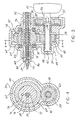
- the motor driven gearbox 30 can best be seen in Figures 3-4.
- the reversible motor 40 is resiliently mounted with respect to the gearbox 30 with a shaft 46 projecting outwardly from the motor 40 into engagement with clutch means 52 for allowing the door to overhaul the power drive system during manual operation, and for transmitting rotary power through the clutch means 52 to drive the door between the open and closed positions during power operations.
- An example of a suitable clutch means 52 is disclosed and illustrated in U.S. Patent US-A-5582279 for "Acceleration Reaction Clutch With Override Capability".
- An output shaft 42 is connected to the clutch means 52 for transferring rotary output power to a pinion gear or driving gear 58.
- the shaft 42 extends within a housing 44 and is supported for rotation by bearings 48 with respect to the housing 44.
- the shaft 42 is resiliently coupled to a hub 50 of the driving gear 58 for rotation therewith.
- the driving or pinion gear 58 includes a plurality of first gear teeth 60 intermeshingly engaged with a plurality of second gear teeth 62 connected to ball nut drive means 64.
- the ball nut drive means 64 is rotatably disposed within the housing 44 by bearings 66 for selectively moving the drive member 34 longitudinally to position the movable closure or sliding door between the open and closed positions with respect to the portal defining the passage through the barrier.
- the barrier is a construction forming an extended indefinite surface preventing or inhibiting the passage of persons or things, and can include a wall, ceiling, roof or cover for a stationary structure or a movable vehicle, such as the van V.
- the portal is structure defining an opening through the barrier for passage of persons or things, such as the framing of a door, window, hatch or roof panel opening.
- the movable closure is an obstructive structure whose presence in or before a passage bars traffic through the passage and is mounted to move in a regular, repetitive, predetermined path with respect to the portal so as to alternately open or close the passage, and can take the form of a hatch, a sliding window, a roof panel or a sliding door D.
- Linear movement motor means or motor driven gearbox 30 causes the drive element 34 to move in a substantially linear or uni-directional path which may be straight, curved, or tortuous. While the ball nut drive means 64 provides for reversing the direction of movement of the movable drive member 34, the drive member 34 is not pivoted substantially about the longitudinal axis of the elongated drive member 34 as the ball nut drive means 64 rotates with respect to the housing 44.
- the drive member 34 preferably includes a rigid or resilient screw-like member portion extending along at least a portion of a longitudinal length of the drive member cooperatively engageable with the ball nut drive means 64. A portion of the drive member 34 may be covered by a drive sheath 86 at least partially between gearbox 30 and the sliding door D. Preferably, the drive member 34 also includes a flexible push/pull cable portion connectible to the sliding door at one end and connected to the screw-like portion at an opposite end by suitable means, such as crimping, silver soldering, welding, or a combination thereof.
- the screw-like member portion of drive member 34 can extend along a portion of a longitudinal length of the drive member 34 cooperatively engageable with the ball nut drive means 64.
- the screw-like member portion can be selected from a group including an acme threaded screw, an angled trapezoidal threaded screw and a square threaded screw.
- the screw-like portion includes helical gear teeth 68, operably engageable with a plurality of balls 72 for driving the drive member 34 longitudinally as the ball nut drive means 64 rotates with respect to the housing 44 in response to rotary power supplied by motor 40 through clutch means 52 and pinion gear 58.
- the plurality of balls 72 are recirculated longitudinally with respect to the ball nut 74 of the drive means 64 through ball return passage 76 as the ball nut 74 rotates with respect to the housing 44 on bearings 66.
- the ball nut 74 can be formed with an overmolded gear 78 having the plurality of second gear teeth 62 connected to the ball nut 74 for rotation therewith.
- Gear means such as pinion gear 58, drives the gear 78 in rotation about a longitudinal axis of the drive member 34.
- the gear 78 and pinion gear 58 can be formed with any desirable gear ratio for the particular application.
- Clutch means 52 connected to the gear means 58 provides for overrunning with respect to the gear means 58 in response to manual manipulation of the movable closure, or for slipping in response to the movable closure contacting an obstruction prior to reaching the open or closed position.
- Storage means 32 houses at least a portion of the drive member 34 opposite from the movable closure with respect to the ball nut drive means 64.
- Sensing means 80 is responsive to rotary movement of the ball nut drive means 64 for transmitting to the electronic control unit 56 a signal representative of the location of the door D along the fixed path.
- the sensing means 80 can include a magnet 82 connected to the ball nut 74 for rotation therewith and a magnetic sensor 84 connected to the housing 44 for sensing the position of the magnet 82 as it passes by the sensor during rotation for transmitting to the electronic control unit 56 a signal representative of the location of the door along the fixed path of travel between the open and closed positions during manual and powered operations.
- the power drive system in the preferred embodiment can include an elongated compound drive member 34 connected to the sliding door D through mounting bracket 38.
- the ball nut drive means 64 selectively moves the drive member 34 longitudinally to position the movable closure between the open and closed positions.
- the compound drive member 34 can include a rigid screw-like portion 88 extending longitudinally a sufficient distance to operably engage with the ball nut drive means 64 as the sliding door D moves between the open and closed positions, and a flexible portion 90 of the elongated compound drive member 34 connected between the sliding door D and the rigid screw-like portion 88.
- the motor 40 drives through clutch means 52, which may include an optional lock, through intermeshing first and second gear teeth, 60 and 62, driving an Acme, square or ball nut screw-like portion 88 through drive nut means 64 to provide linear reversible motion.
- Flexible cable portion 90 attaches to one end of the screw-like portion 88 to add a length of flexible cable 90 to drive an automotive van-type sliding door D through a track 36 and sheath 86 in a non-straight section to the left in the direction of arrow A as depicted in Figure 5.
- the present invention may also be adapted for use on non-automotive applications, such as commercial buildings and homes.
- a storage housing 32 or sheath is provided to maintain quiet operation.
- the present invention may also be adapted to employ a through motor configuration, such that the elongated drive member 34 extends through an aperture formed in the motor, such that the motor completely surrounds a portion of the drive member 34 while powering the sliding door D between the open and closed positions.
- the flexible portion 90 attached to the end of the screw-like portion 88 allows the present invention to drive a sliding door D along a curved or other non-linear track.
- the motor 40 can be adapted to use a through motor construction without a clutch.
- the motor 40 and clutch means 52 can be adapted to employ a through motor construction.
- a hollow shaft can be provided to allow clearance for the ball, or Acme threaded screw to power the sliding door D between the open and closed positions.
- the reversible motor 40 can have a hollow shaft 46 allowing passage of the drive member 34 through the shaft 46 and motor 40.
- the shaft 46 sheathes a portion of the drive member 34 passing therethrough, and is connected to the ball nut drive means 64.
- the shaft 46 can be directly connected to the ball nut 74, or can be connected through a clutch means 52 (not shown in Figure 7).
- the drive member 34 can be a rigid screw-like member, or worm gear, or a flexible cable member having a flexible core 70 and at least one helically wound gear tooth 68 as previously described passing through the gear box 30 including the housing 44 and drive ball nut 74.
- the balls 72 within the ball nut 74 drivingly engage the gear tooth or teeth 68 of the drive member 34 to move the drive member 34 longitudinally in either direction.
- the drive member 34 can be sheathed along at least a portion of its longitudinal length.
- the balls 72 are recirculated through recirculating passageway 76.
- the ball nut drive means 64 is rotatably mounted on bearing 66 within the housing 44. This can permit free-wheeling of the ball nut 74 and connected shaft 46 in response to manual manipulation of the movable closure or sliding door D.
- bracket means 38 is operably connected to the movable closure, and can preferably be connected generally midway between the first and second edges as seen in Fig. 1.
- the conventional bracket and roller assemblies, and the bracket means 38 are slidingly supported in corresponding guide rails and guide means, such as cable guide track 36 respectively to guide the movable closure through opening and closing movements with respect to the barrier.
- the guide means or track 36 is connected to the barrier generally midway between the first and second guide tracks respectively, and operably engages the bracket means 38 for guiding the bracket means 38 along the fixed path between the opened and closed positions of the movable closure.
- Elongated means such as drive member 34
- Elongated means is slidably disposed within the guide means 36 and connected to the bracket means 38 for driving the bracket means 38 along the fixed path.
- Translator means such as motor 40, is operably engageable with the elongated means 34 for powering movement of the elongated means 34 and connected bracket means 38 with respect to the guide means 36 along the fixed path.
- the rear guide means includes an elongated track or housing 36.
- the track 36 typically defines at least two surfaces 92 and 94 disposed at an angle with respect to one another engageable with rollers 96 and 98 respectively.
- the rollers 96 and 98 typically have axes of rotation that are disposed at an angle with respect to one another, generally corresponding to a 90° angle as illustrated in Figure 6.
- the guide means or track 36 defines a slot 100 of sufficient dimension to permit the bracket means 38 to extend therethrough.
- the track 36 generally defines a first chamber for receiving the rollers 96 and 98, and a second chamber for slidably receiving the elongated means or drive member 34.
- the first and second chambers are in communication with one another longitudinally along the length of the track 36 allowing attachment of the bracket means 38 to the elongated means 34, such as by coupling member 102.
Landscapes
- Engineering & Computer Science (AREA)
- Mechanical Engineering (AREA)
- Power-Operated Mechanisms For Wings (AREA)
- Transmission Devices (AREA)
Abstract
Description
US 5,105,131 discloses a power drive system for moving a door between a closed position in which the door is sealingly seated in a door opening and an open position in which the door is disposed at the side of the van rearwardly of the door opening. The door opening is provided in the wall of a van. The sliding door is coupled to an elongate flexible push-/pull cable. Further, the power drive system includes a reversible motor. Transmission of movement between the motor and the elongate member is performed via a rotary gear meashing with an helically wound member of the cable.
FR 2 359 954 shows an arrangement for moving a car window. The window moves along a linear fixed path. An elongate drive member consists of a spring type element.
Claims (13)
- Power drive system for moving a moveable closure between an open position and a closed position along a non-linear fixed path with respect to a portal defining a passage through a barrier, with a reversible power drive means and with an elongate drive member connecting the power drive means to the closure, characterized in that said elongate drive member has a flexible portion connectable to said moveable closure and a rigid portion extending longitudinally and being connected to the power drive means; ball nut drive means being engageable with said rigid portion of said elongate drive member selectively moves said elongate drive member longitudinally to position said moveable closure between said open and closed positions.
- Power drive system as claimed in claim 1, characterized in that clutch means is provided for overrunning to accomodate manual manipulation of said moveable closure along said non-linear fixed path and engaging for powered operation of said moveable closure along said non-linear fixed path.
- Power drive system as claimed in one of claims 1 or 2, characterized in that a recirculating ball nut drive means operably connects to said rotary drive means and engages said elongate drive member for translating rotary motion of said power drive means into linear motion of said elongate drive member.
- Power drive system as claimed in one of claims 1 to 3, charcterized in that said reversible power drive means has a hollow shaft allowing passage of said rigid portion of said elongate drive member therethrough.
- Power drive system as claimed in claim 4, characterized in that said ball nut drive means directly couples to said hollow shaft of said reversible power drive means for linearly driving said elongate drive member through said ball nut and hollow shaft.
- Power drive system as claimed in one of claims 1 to 5, characterized in that gear means has a plurality of first gear teeth for driving said drive member longitudinally;
ball nut drive means having a gear with a plurality of second gear teeth connected to said ball nut for rotation therewith, such that said plurality of first and second gear teeth intermeshingly engage to drive said ball nut in rotation, said ball nut for translating rotation of said ball nut about a longitudinal axis of said drive member into linear movement of said drive member between said open and closed positions. - Power drive system as claimed in claim 6, characterized in that electric motor means is connected to said clutch means for driving said elongate drive member in linear movement through said gear means and ball nut.
- Power drive means as claimed in one of claims 1 to 7, characterized in that reversible electric motor means drives said elongate drive member in linear movement to move said moveable closure between said open and closed positions, said motor means connected to said ball nut drive means with said elongate drive member extending through said motor means and said ball nut drive means.
- Power drive system as claimed in one of claims 1 to 8, characterized in that said elongated drive member having a flexible portion connected to said moveable closure and a resilient screw-like portion extending longitudinally sufficiently to operably engage with said ball nut drive means as said moveable closure moves between said open and closed positions, said screw-like portion selected from the group including an acme threaded screw, an angled trapezoidal threaded screw and a square threaded screw.
- Power drive system as claimed in one of claims 1 to 9, characterized in that storage means for housing at least a portion of said drive member opposite from said moveable closure with respect to said ball nut drive means.
- Power drive system as claimed in one of claims 1 to 10, characterized in that control means selectively operates said power drive means and included an electronic control unit responsive to a signal representative of the location of said closure to perform selected door control functions when said door is at selected locations along its fixed path.
- Power drive system as claimed in claim 11, characterized in that sensing means responsive to rotary movement of said ball nut drive means transmits to said electronic control unit a signal representative of the location of said door along its fixed path.
- Sliding door of a vehicle, particularly of a van, characterized in that it includes a power drive system as claimed in one of claims 1 to 12.
Applications Claiming Priority (3)
| Application Number | Priority Date | Filing Date | Title |
|---|---|---|---|
| US575823 | 1995-12-20 | ||
| US08/575,823 US5644869A (en) | 1995-12-20 | 1995-12-20 | Power drive for a movable closure with ball nut drive screw |
| PCT/US1996/020084 WO1997022776A1 (en) | 1995-12-20 | 1996-12-19 | Power drive for a movable closure with ball nut drive screw |
Publications (2)
| Publication Number | Publication Date |
|---|---|
| EP0853714A1 EP0853714A1 (en) | 1998-07-22 |
| EP0853714B1 true EP0853714B1 (en) | 2004-03-03 |
Family
ID=24301854
Family Applications (1)
| Application Number | Title | Priority Date | Filing Date |
|---|---|---|---|
| EP96945213A Expired - Lifetime EP0853714B1 (en) | 1995-12-20 | 1996-12-19 | Power drive for a movable closure with ball nut drive screw |
Country Status (6)
| Country | Link |
|---|---|
| US (1) | US5644869A (en) |
| EP (1) | EP0853714B1 (en) |
| AT (1) | ATE261048T1 (en) |
| DE (1) | DE69631776T2 (en) |
| ES (1) | ES2213186T3 (en) |
| WO (1) | WO1997022776A1 (en) |
Cited By (2)
| Publication number | Priority date | Publication date | Assignee | Title |
|---|---|---|---|---|
| US8493081B2 (en) | 2009-12-08 | 2013-07-23 | Magna Closures Inc. | Wide activation angle pinch sensor section and sensor hook-on attachment principle |
| US9234979B2 (en) | 2009-12-08 | 2016-01-12 | Magna Closures Inc. | Wide activation angle pinch sensor section |
Families Citing this family (50)
| Publication number | Priority date | Publication date | Assignee | Title |
|---|---|---|---|---|
| US6904717B2 (en) | 1995-07-12 | 2005-06-14 | Valeo Electrical Systems, Inc. | Method for controlling a power sliding van door |
| US5979114A (en) | 1995-07-12 | 1999-11-09 | Valeo Electrical Systems, Inc. | Electronic control and method for power sliding van door with rear-center-mounted drive |
| US5832669A (en) * | 1995-08-24 | 1998-11-10 | Mitsui Kinzoku Kogyo Kabushiki Kaisha | Latch device for vehicle sliding door |
| JP3188839B2 (en) * | 1996-04-02 | 2001-07-16 | 三井金属鉱業株式会社 | Driving cable waterproof device for auto sliding door |
| JP3294121B2 (en) * | 1996-10-25 | 2002-06-24 | 株式会社ミツバ | Automatic switchgear for vehicles |
| US6125583A (en) * | 1997-08-13 | 2000-10-03 | Atoma International Inc. | Power sliding mini-van door |
| FR2784349B1 (en) * | 1998-10-09 | 2000-12-29 | Labinal | ACTUATOR FOR OPERATING AN ACCESS HATCH AND ACCESS HATCH COMPRISING SAME |
| EP1002923A3 (en) * | 1998-11-18 | 2003-03-05 | Apprich Secur 2000 GmbH | Device for opening and closing an opening in a wall using a sliding door |
| JP3591349B2 (en) * | 1998-12-22 | 2004-11-17 | アイシン精機株式会社 | Sliding door device for vehicles |
| EP1159504B1 (en) | 1999-03-08 | 2004-05-19 | Intier Automotive Closures Inc. | Drive mechanism for selectively opening and closing a closure panel manually or automatically |
| JP3844943B2 (en) * | 2000-04-03 | 2006-11-15 | Ntn株式会社 | Ball screw and electric power steering apparatus including the same |
| US7144068B2 (en) * | 2003-11-20 | 2006-12-05 | Intier Automotive Closures Inc. | Drive mechanism for selectively opening and closing a closure panel manually or automatically |
| DE102004034452A1 (en) * | 2004-07-16 | 2006-02-09 | Siemens Ag | cable drive |
| US7185943B2 (en) * | 2004-10-15 | 2007-03-06 | Automotive Components Holdings, Llc | Two piece sliding window panel having lead screw power unit |
| US7367598B2 (en) * | 2005-02-07 | 2008-05-06 | Delphi Technologies, Inc. | Power striker with manual override |
| US7445258B2 (en) * | 2005-02-07 | 2008-11-04 | Delphi Technologies, Inc. | Power linear displacement striker |
| JP2007297796A (en) * | 2006-04-28 | 2007-11-15 | Fuji Electric Systems Co Ltd | Mobile drive unit |
| US7810282B2 (en) * | 2006-09-25 | 2010-10-12 | Magna Closures Inc. | Belt-driven rack gear power sliding door |
| DE102006051847A1 (en) * | 2006-11-03 | 2008-05-08 | Conti Temic Microelectronic Gmbh | Movement detecting device for electrically operating sliding door, has molding arranged on traction-shear-cable that pulls and/or pushes sliding door, where drive wheel is provided for moving traction-shear-cable |
| DE102006051846A1 (en) * | 2006-11-03 | 2008-05-08 | Conti Temic Microelectronic Gmbh | Device for moving electrically operated door, has pulling-pushing rope, which pulls and pushes door, where drive wheel is provided to move pulling-pushing rope |
| KR101467422B1 (en) | 2007-08-06 | 2014-12-01 | 스트라텍 파워 액세스 엘엘씨 | Linear drive actuator for a movable vehicle panel |
| DE102007059564C5 (en) * | 2007-12-11 | 2014-04-24 | Stabilus Gmbh | driving means |
| US9260882B2 (en) | 2009-03-12 | 2016-02-16 | Ford Global Technologies, Llc | Universal global latch system |
| US8573657B2 (en) * | 2009-03-12 | 2013-11-05 | Ford Global Technologies, Llc | Latch mechanism |
| US9551166B2 (en) | 2011-11-02 | 2017-01-24 | Ford Global Technologies, Llc | Electronic interior door release system |
| US9260902B2 (en) | 2013-09-13 | 2016-02-16 | Taylor Made Group, Llc | Sliding roof window |
| US9416565B2 (en) | 2013-11-21 | 2016-08-16 | Ford Global Technologies, Llc | Piezo based energy harvesting for e-latch systems |
| US9834964B2 (en) | 2014-05-13 | 2017-12-05 | Ford Global Technologies, Llc | Powered vehicle door latch and exterior handle with sensor |
| US10119308B2 (en) | 2014-05-13 | 2018-11-06 | Ford Global Technologies, Llc | Powered latch system for vehicle doors and control system therefor |
| US10273725B2 (en) | 2014-05-13 | 2019-04-30 | Ford Global Technologies, Llc | Customer coaching method for location of E-latch backup handles |
| US10323442B2 (en) | 2014-05-13 | 2019-06-18 | Ford Global Technologies, Llc | Electronic safe door unlatching operations |
| US9903142B2 (en) | 2014-05-13 | 2018-02-27 | Ford Global Technologies, Llc | Vehicle door handle and powered latch system |
| US9909344B2 (en) | 2014-08-26 | 2018-03-06 | Ford Global Technologies, Llc | Keyless vehicle door latch system with powered backup unlock feature |
| US9939054B2 (en) | 2015-10-09 | 2018-04-10 | Command Access Technology, Inc. | Actuator with ball screw drive |
| US9725069B2 (en) | 2015-10-12 | 2017-08-08 | Ford Global Technologies, Llc | Keyless vehicle systems |
| US10550610B2 (en) | 2016-06-22 | 2020-02-04 | Ford Global Technologies, Llc | Inside override emergency handle for door release |
| US10227810B2 (en) | 2016-08-03 | 2019-03-12 | Ford Global Technologies, Llc | Priority driven power side door open/close operations |
| US10087671B2 (en) | 2016-08-04 | 2018-10-02 | Ford Global Technologies, Llc | Powered driven door presenter for vehicle doors |
| US10329823B2 (en) | 2016-08-24 | 2019-06-25 | Ford Global Technologies, Llc | Anti-pinch control system for powered vehicle doors |
| US10458171B2 (en) | 2016-09-19 | 2019-10-29 | Ford Global Technologies, Llc | Anti-pinch logic for door opening actuator |
| JP6851855B2 (en) * | 2017-02-28 | 2021-03-31 | ダイハツ工業株式会社 | Electric sliding door control device |
| US10604970B2 (en) | 2017-05-04 | 2020-03-31 | Ford Global Technologies, Llc | Method to detect end-of-life in latches |
| DE102017220326B4 (en) | 2017-11-15 | 2022-10-06 | Ford Global Technologies, Llc | Method of operating a motor drive device of a vehicle sliding door |
| US10907386B2 (en) | 2018-06-07 | 2021-02-02 | Ford Global Technologies, Llc | Side door pushbutton releases |
| US20190383084A1 (en) | 2018-06-14 | 2019-12-19 | Magna Mirrors Of America, Inc. | Slider window assembly with movable panel drive system |
| DE102018122353A1 (en) * | 2018-09-13 | 2020-03-19 | Kiekert Aktiengesellschaft | Motor vehicle sliding door unit |
| US11331984B2 (en) | 2019-01-28 | 2022-05-17 | Magna Mirrors Of America, Inc. | Dual slider window assembly |
| US11952820B1 (en) | 2020-07-15 | 2024-04-09 | Magna Mirrors Of America, Inc. | Slider window assembly with movable panel drive system |
| US11339601B2 (en) * | 2020-07-27 | 2022-05-24 | Rivian Ip Holdings, Llc | Power pocket sliding door |
| US12152429B2 (en) | 2021-04-16 | 2024-11-26 | D&D-Sw, Llc | Automated window mechanism with releasable clutch |
Family Cites Families (83)
| Publication number | Priority date | Publication date | Assignee | Title |
|---|---|---|---|---|
| GB1065562A (en) * | 1965-01-14 | 1967-04-19 | Morris Ltd Herbert | Improvements in mean for automatically operating and controlling reciprocating motion |
| US3334443A (en) * | 1965-09-30 | 1967-08-08 | Dura Corp | Vehicle window and regulator assembly |
| GB1199479A (en) * | 1967-10-23 | 1970-07-22 | Electricity Council | Improvements in or relating to Door Operating Mechanisms. |
| FR2029134A5 (en) * | 1969-01-14 | 1970-10-16 | Mecanismes Comp Ind De | |
| US3653154A (en) * | 1970-02-11 | 1972-04-04 | Power Car Door Corp | Door actuator |
| DE2210828A1 (en) * | 1972-03-07 | 1973-09-13 | Eaton Gmbh | AUTOMATIC DRIVE FOR SLIDING DOORS |
| US3785089A (en) * | 1972-07-14 | 1974-01-15 | W Smith | Door operator |
| US3874117A (en) * | 1973-09-28 | 1975-04-01 | R H Boehm Company Inc | Electric door opener |
| US4050189A (en) * | 1974-05-24 | 1977-09-27 | C. Hager & Sons Hinge Manufacturing Company | Device for operating a pocket door |
| IT1070632B (en) * | 1976-07-27 | 1985-04-02 | Riv Officine Di Villar Perosa | WINDOW REGULATOR WITH ELECTRIC CONTROL..PARTICULARLY FOR VEHICLES |
| GB1559695A (en) * | 1976-11-26 | 1980-01-23 | Vauxhall Motors Ltd | Motor vehicle having a sliding door |
| JPS5387426A (en) * | 1977-01-12 | 1978-08-01 | Nissan Motor Co Ltd | Apparatus for sliding slide door for vehicle |
| US4234833A (en) * | 1978-01-19 | 1980-11-18 | A. E. Moore Company, Inc. | Door operator system using counter circuit for determining limit positions |
| US4852422A (en) * | 1978-03-30 | 1989-08-01 | Aisin Seiki Kabushiki Kaisha | Driving cable connection |
| US4186524A (en) * | 1978-04-14 | 1980-02-05 | General Motors Corporation | Power actuator for pivotable window |
| AR213370A1 (en) * | 1978-06-12 | 1979-01-15 | Pecchioni V | INTEGRAL UNIT OF LIFTING DOOR AND FRAME FOR THE SAME |
| US4330960A (en) * | 1979-12-18 | 1982-05-25 | Dorma-Baubeschlag Gmbh & Co. Kg. | Closing arrangement for sliding doors and the like |
| US4313281A (en) * | 1980-03-03 | 1982-02-02 | Richmond Moscow K | Gate opening and closing apparatus and method |
| GB2082660B (en) * | 1980-08-30 | 1984-03-28 | Nissan Motor | Sliding plug door for a vehicle |
| JPS5876669A (en) * | 1981-10-29 | 1983-05-09 | 株式会社大井製作所 | Automatic door opening and closing apparatus automobile |
| JPS58110778A (en) * | 1981-12-23 | 1983-07-01 | ワイケイケイ株式会社 | Automatic opening/closing door control device |
| US4462185A (en) * | 1982-03-12 | 1984-07-31 | Toyota Shatai Kabushiki Kaisha | Door operating device for a slide door unit |
| JPS58165641A (en) * | 1982-03-26 | 1983-09-30 | Asmo Co Ltd | Mounting structure of dc motor for automobile |
| DE3231181A1 (en) * | 1982-08-21 | 1984-02-23 | Gebr. Bode & Co, 3500 Kassel | SUSPENSION DEVICE FOR THE DOOR LEAF OF A PIVOTING SLIDING DOOR FOR VEHICLES, IN PARTICULAR. RAIL VEHICLES |
| JPS59192176A (en) * | 1983-04-14 | 1984-10-31 | 日産自動車株式会社 | Automatic opening and closing apparatus for automobile |
| US4563625A (en) * | 1984-05-17 | 1986-01-07 | The Stanley Works | Automatic door control system |
| DE3419338A1 (en) * | 1984-05-24 | 1985-11-28 | Gebr. Bode & Co GmbH, 3500 Kassel | DRIVING DEVICE FOR THE DOOR LEAF OF A PIVOTING SLIDING DOOR, ESPECIALLY FOR VEHICLES |
| GB2164090B (en) * | 1984-07-26 | 1987-10-14 | Ohi Seisakusho Co Ltd | Automatic sliding door system for vehicles |
| DE3538837A1 (en) * | 1984-11-02 | 1986-05-07 | Ohi Seisakusho Co., Ltd., Yokohama, Kanagawa | OPENING AND CLOSING MECHANISM FOR A SLIDING DOOR |
| US4769584A (en) * | 1985-06-18 | 1988-09-06 | Thomas J. Ring | Electronic controller for therapeutic table |
| US4801172A (en) * | 1985-10-03 | 1989-01-31 | Townsend John A | Vehicle closure |
| FR2594167B1 (en) * | 1986-02-07 | 1988-06-10 | Farnier & Penin | GUIDING DEVICE FOR SLIDING AND LIGHTING PANEL, PARTICULARLY FOR VEHICLE DOOR. |
| JPH0613358Y2 (en) * | 1986-03-26 | 1994-04-06 | 吉田工業株式会社 | Automatic door |
| US4702514A (en) * | 1986-04-15 | 1987-10-27 | Perry Arthur H | Sliding door |
| US4914859A (en) * | 1987-04-16 | 1990-04-10 | Lanson Electronics, Inc. | Automatic door safety system |
| US4794731A (en) * | 1987-06-15 | 1989-01-03 | The Chamberlain Group, Inc. | Twin sprocket garage door opener |
| US4887390A (en) * | 1987-12-18 | 1989-12-19 | Masco Industries, Inc. | Powered sliding door opener/closer for vehicles |
| US4862640A (en) * | 1987-12-18 | 1989-09-05 | Masco Industries, Inc. | Powered sliding door opener/closer for vehicles |
| JPH01163386A (en) * | 1987-12-18 | 1989-06-27 | Nippon Denso Co Ltd | Switchgear of door for car |
| JPH01303081A (en) * | 1988-05-31 | 1989-12-06 | Nikon Corp | Controller |
| GB8904644D0 (en) * | 1989-03-01 | 1989-04-12 | Raytel Group The Limited | Electromagnetic communication interface |
| US4916861A (en) * | 1989-03-03 | 1990-04-17 | Itt Corporation | Variable power drive for sliding door |
| US5004280A (en) * | 1989-03-03 | 1991-04-02 | Itt Corporation | Variable power drive for sliding door |
| US5172947A (en) * | 1989-03-03 | 1992-12-22 | Itt Corporation | Power striker for sliding door latch |
| US4967083A (en) * | 1989-04-14 | 1990-10-30 | The Stanley Works | Door sensor system |
| US4922168A (en) * | 1989-05-01 | 1990-05-01 | Genie Manufacturing, Inc. | Universal door safety system |
| ES2028770T1 (en) * | 1989-05-10 | 1992-07-16 | Dorma Gmbh + Co. Kg | AUTOMATIC SLIDING DOOR. |
| ATE95764T1 (en) * | 1989-06-02 | 1993-10-15 | Ife Gmbh | PIVOT SLIDING DOOR FOR VEHICLES. |
| US5076016A (en) * | 1989-10-04 | 1991-12-31 | Asc Incorporated | Powered sliding door system |
| JPH0747586Y2 (en) * | 1989-11-30 | 1995-11-01 | 株式会社大井製作所 | Automatic door closing device |
| JP2505445Y2 (en) * | 1990-02-23 | 1996-07-31 | 株式会社大井製作所 | Door lock half latch and full latch detection device |
| US4984385A (en) * | 1990-03-22 | 1991-01-15 | Masco Industries, Inc. | Powered closing assist mechanism for vehicle doors or lid members |
| US5025591A (en) * | 1990-03-22 | 1991-06-25 | Masco Industries, Inc. | Varying radius helical cable spool for powered vehicle door systems |
| US5062241A (en) * | 1990-03-22 | 1991-11-05 | Masco Industries, Inc. | Varying radius helical cable spool for powered vehicle door systems |
| US5069000A (en) * | 1990-03-22 | 1991-12-03 | Masco Industries, Inc. | Reversing apparatus for powered vehicle door systems |
| US5140316A (en) * | 1990-03-22 | 1992-08-18 | Masco Industries, Inc. | Control apparatus for powered vehicle door systems |
| US5189839A (en) * | 1990-03-22 | 1993-03-02 | Masco Industries, Inc. | Control apparatus for powered vehicle door systems |
| FR2660963B1 (en) * | 1990-04-11 | 1992-08-07 | Faiveley Transport | ACTUATOR WITH NUT AND REVERSIBLE SCREW AND SLIDING DOOR EQUIPPED WITH SUCH A DEVICE. |
| US5138795A (en) * | 1990-04-25 | 1992-08-18 | General Motors Corporation | Power sliding door closer |
| US5046283A (en) * | 1990-04-25 | 1991-09-10 | General Motors Corporation | Power sliding door closer |
| US5063710A (en) * | 1990-09-24 | 1991-11-12 | Itt Corporation | Power drive for sliding door |
| US5066056A (en) * | 1990-09-24 | 1991-11-19 | Itt Corporation | Power striker for automotive door latch |
| US5105131A (en) * | 1990-09-24 | 1992-04-14 | Alfred Teves Gmbh | Power drive system for sliding door |
| US5039925A (en) * | 1990-09-24 | 1991-08-13 | Itt Corporation | Position encoder for sliding door power drive system |
| US5142152A (en) * | 1991-01-02 | 1992-08-25 | The Stanley Works | Sliding door sensor |
| CA2067594C (en) * | 1991-05-10 | 1997-02-25 | Mark Iv Transportation Products Corporation | Transit car power door obstruction sensing system and device |
| NL9100951A (en) * | 1991-06-03 | 1993-01-04 | Tbl Beheer Bv | SWING SLIDING DOOR SYSTEM FOR A VEHICLE. |
| CA2117092A1 (en) * | 1991-09-06 | 1993-03-18 | Dan C. Yingling | Automatic door operator |
| FR2684049B1 (en) * | 1991-11-27 | 1994-03-04 | Peugeot Automobiles | DEVICE FOR GUIDING A SLIDING OPENING DEVICE SUCH AS A SLIDING DOOR, PARTICULARLY FOR A MOTOR VEHICLE. |
| US5282663A (en) * | 1992-01-10 | 1994-02-01 | Utility Trailer Manufacturing Company | Retracting system for flexible side walls for cargo vehicles |
| US5319990A (en) * | 1992-02-05 | 1994-06-14 | California Technical Marketing Inc. | Cover system utilizing band |
| DE4230867C2 (en) * | 1992-09-16 | 2003-06-12 | Bode & Co Geb | Sliding door for vehicles, in particular vehicles for public transport |
| GB2271384B (en) * | 1992-10-06 | 1996-06-19 | Soley Antonio Codina | Improvements in and relating to sliding doors |
| US5285596A (en) * | 1992-11-13 | 1994-02-15 | Kinsey Kenneth M | Door closure apparatus |
| US5233789A (en) * | 1992-11-16 | 1993-08-10 | General Motors Corporation | Adjustable cable guide assembly for powered sliding vehicle door closer |
| US5323570A (en) * | 1993-01-25 | 1994-06-28 | General Motors Corporation | Door opening cable system with cable slack take-up |
| US5319880A (en) * | 1993-01-25 | 1994-06-14 | General Motors Corporation | Sliding door opening cable system with cable slack take-up |
| US5316365A (en) * | 1993-01-25 | 1994-05-31 | General Motors Corporation | Sliding door closed loop cable closure system with balanced cable tension and varying diameter pulleys |
| US5319881A (en) * | 1993-01-25 | 1994-06-14 | General Motors Corporation | Sliding door closed loop cable closure system with balanced cable length and varying diameter pulleys |
| US5263762A (en) * | 1993-02-16 | 1993-11-23 | General Motors Corporation | Vehicle with sliding door contact closure sensor |
| US5347755A (en) * | 1993-02-19 | 1994-09-20 | Ready Metal Manufacturing Company | Automatically actuated door arrangement |
| US5361540A (en) * | 1993-09-29 | 1994-11-08 | General Motors Corporation | Door check for vehicle sliding door |
| US5422552A (en) * | 1994-06-17 | 1995-06-06 | Parisi; Gary | Automated actuator for sliding panels |
-
1995
- 1995-12-20 US US08/575,823 patent/US5644869A/en not_active Expired - Lifetime
-
1996
- 1996-12-19 ES ES96945213T patent/ES2213186T3/en not_active Expired - Lifetime
- 1996-12-19 DE DE69631776T patent/DE69631776T2/en not_active Expired - Fee Related
- 1996-12-19 WO PCT/US1996/020084 patent/WO1997022776A1/en not_active Ceased
- 1996-12-19 AT AT96945213T patent/ATE261048T1/en not_active IP Right Cessation
- 1996-12-19 EP EP96945213A patent/EP0853714B1/en not_active Expired - Lifetime
Cited By (3)
| Publication number | Priority date | Publication date | Assignee | Title |
|---|---|---|---|---|
| US8493081B2 (en) | 2009-12-08 | 2013-07-23 | Magna Closures Inc. | Wide activation angle pinch sensor section and sensor hook-on attachment principle |
| US9234979B2 (en) | 2009-12-08 | 2016-01-12 | Magna Closures Inc. | Wide activation angle pinch sensor section |
| US9417099B2 (en) | 2009-12-08 | 2016-08-16 | Magna Closures Inc. | Wide activation angle pinch sensor section |
Also Published As
| Publication number | Publication date |
|---|---|
| EP0853714A1 (en) | 1998-07-22 |
| DE69631776T2 (en) | 2004-07-29 |
| ES2213186T3 (en) | 2004-08-16 |
| DE69631776D1 (en) | 2004-04-08 |
| US5644869A (en) | 1997-07-08 |
| ATE261048T1 (en) | 2004-03-15 |
| WO1997022776A1 (en) | 1997-06-26 |
Similar Documents
| Publication | Publication Date | Title |
|---|---|---|
| US5644869A (en) | Power drive for a movable closure with ball nut drive screw | |
| US5787636A (en) | Power drive for a movable closure with ball nut driven flexible cable | |
| US5755059A (en) | Solenoid operated clutch for powered sliding door | |
| US5906071A (en) | Rear-center-mounted power door actuator | |
| US11725428B2 (en) | Power actuator with self disengaging clutch unit | |
| US6904717B2 (en) | Method for controlling a power sliding van door | |
| US10378263B2 (en) | Power swing door actuator with articulating linkage mechanism | |
| US6430875B1 (en) | Electronic control and method for power sliding van door with rear-center-mounted drive | |
| US6341448B1 (en) | Cinching latch | |
| US5105131A (en) | Power drive system for sliding door | |
| US6321488B1 (en) | Power sliding vehicle door | |
| US5046283A (en) | Power sliding door closer | |
| US6588829B2 (en) | Method for operating a vehicle power sliding door | |
| US20180258682A1 (en) | Power swing door drive actuator | |
| US5765886A (en) | Power striker with inertially activated impact cycle | |
| US5755468A (en) | Power striker with over-ride capabilities | |
| WO1997040995B1 (en) | Solenoid operated clutch for powered sliding door | |
| CA2409202C (en) | Powered sliding panel with secondary articulation for a motor vehicle | |
| CA2411325C (en) | Lost motion mechanism for power liftgate closure system | |
| US5062241A (en) | Varying radius helical cable spool for powered vehicle door systems | |
| US20220186529A1 (en) | Door system for motor vehicles providing power present and hold functions and equipped with a closure latch assembly having a power release and safety catch arrangement | |
| EP0868589B1 (en) | Rear center mounted power door actuator | |
| JP2009057773A (en) | Automatic opening/closing device for vehicle |
Legal Events
| Date | Code | Title | Description |
|---|---|---|---|
| PUAI | Public reference made under article 153(3) epc to a published international application that has entered the european phase |
Free format text: ORIGINAL CODE: 0009012 |
|
| 17P | Request for examination filed |
Effective date: 19971229 |
|
| AK | Designated contracting states |
Kind code of ref document: A1 Designated state(s): AT BE CH DE DK ES FI FR GB GR IE IT LI LU MC NL PT SE |
|
| 17Q | First examination report despatched |
Effective date: 20000214 |
|
| GRAP | Despatch of communication of intention to grant a patent |
Free format text: ORIGINAL CODE: EPIDOSNIGR1 |
|
| GRAS | Grant fee paid |
Free format text: ORIGINAL CODE: EPIDOSNIGR3 |
|
| GRAA | (expected) grant |
Free format text: ORIGINAL CODE: 0009210 |
|
| RAP1 | Party data changed (applicant data changed or rights of an application transferred) |
Owner name: VALEO ELECTRICAL SYSTEMS, INC. |
|
| AK | Designated contracting states |
Kind code of ref document: B1 Designated state(s): AT BE CH DE DK ES FI FR GB GR IE IT LI LU MC NL PT SE |
|
| PG25 | Lapsed in a contracting state [announced via postgrant information from national office to epo] |
Ref country code: NL Free format text: LAPSE BECAUSE OF FAILURE TO SUBMIT A TRANSLATION OF THE DESCRIPTION OR TO PAY THE FEE WITHIN THE PRESCRIBED TIME-LIMIT Effective date: 20040303 Ref country code: LI Free format text: LAPSE BECAUSE OF FAILURE TO SUBMIT A TRANSLATION OF THE DESCRIPTION OR TO PAY THE FEE WITHIN THE PRESCRIBED TIME-LIMIT Effective date: 20040303 Ref country code: FI Free format text: LAPSE BECAUSE OF FAILURE TO SUBMIT A TRANSLATION OF THE DESCRIPTION OR TO PAY THE FEE WITHIN THE PRESCRIBED TIME-LIMIT Effective date: 20040303 Ref country code: CH Free format text: LAPSE BECAUSE OF FAILURE TO SUBMIT A TRANSLATION OF THE DESCRIPTION OR TO PAY THE FEE WITHIN THE PRESCRIBED TIME-LIMIT Effective date: 20040303 Ref country code: BE Free format text: LAPSE BECAUSE OF FAILURE TO SUBMIT A TRANSLATION OF THE DESCRIPTION OR TO PAY THE FEE WITHIN THE PRESCRIBED TIME-LIMIT Effective date: 20040303 Ref country code: AT Free format text: LAPSE BECAUSE OF FAILURE TO SUBMIT A TRANSLATION OF THE DESCRIPTION OR TO PAY THE FEE WITHIN THE PRESCRIBED TIME-LIMIT Effective date: 20040303 |
|
| REG | Reference to a national code |
Ref country code: GB Ref legal event code: FG4D |
|
| REG | Reference to a national code |
Ref country code: CH Ref legal event code: EP |
|
| REG | Reference to a national code |
Ref country code: IE Ref legal event code: FG4D |
|
| REF | Corresponds to: |
Ref document number: 69631776 Country of ref document: DE Date of ref document: 20040408 Kind code of ref document: P |
|
| PG25 | Lapsed in a contracting state [announced via postgrant information from national office to epo] |
Ref country code: SE Free format text: LAPSE BECAUSE OF FAILURE TO SUBMIT A TRANSLATION OF THE DESCRIPTION OR TO PAY THE FEE WITHIN THE PRESCRIBED TIME-LIMIT Effective date: 20040603 Ref country code: GR Free format text: LAPSE BECAUSE OF FAILURE TO SUBMIT A TRANSLATION OF THE DESCRIPTION OR TO PAY THE FEE WITHIN THE PRESCRIBED TIME-LIMIT Effective date: 20040603 Ref country code: DK Free format text: LAPSE BECAUSE OF FAILURE TO SUBMIT A TRANSLATION OF THE DESCRIPTION OR TO PAY THE FEE WITHIN THE PRESCRIBED TIME-LIMIT Effective date: 20040603 |
|
| NLV1 | Nl: lapsed or annulled due to failure to fulfill the requirements of art. 29p and 29m of the patents act | ||
| REG | Reference to a national code |
Ref country code: ES Ref legal event code: FG2A Ref document number: 2213186 Country of ref document: ES Kind code of ref document: T3 |
|
| REG | Reference to a national code |
Ref country code: CH Ref legal event code: PL |
|
| ET | Fr: translation filed | ||
| PG25 | Lapsed in a contracting state [announced via postgrant information from national office to epo] |
Ref country code: LU Free format text: LAPSE BECAUSE OF NON-PAYMENT OF DUE FEES Effective date: 20041219 |
|
| PG25 | Lapsed in a contracting state [announced via postgrant information from national office to epo] |
Ref country code: IE Free format text: LAPSE BECAUSE OF NON-PAYMENT OF DUE FEES Effective date: 20041220 |
|
| PG25 | Lapsed in a contracting state [announced via postgrant information from national office to epo] |
Ref country code: MC Free format text: LAPSE BECAUSE OF NON-PAYMENT OF DUE FEES Effective date: 20041231 |
|
| PLBE | No opposition filed within time limit |
Free format text: ORIGINAL CODE: 0009261 |
|
| STAA | Information on the status of an ep patent application or granted ep patent |
Free format text: STATUS: NO OPPOSITION FILED WITHIN TIME LIMIT |
|
| 26N | No opposition filed |
Effective date: 20041206 |
|
| REG | Reference to a national code |
Ref country code: IE Ref legal event code: MM4A |
|
| PG25 | Lapsed in a contracting state [announced via postgrant information from national office to epo] |
Ref country code: PT Free format text: LAPSE BECAUSE OF NON-PAYMENT OF DUE FEES Effective date: 20040803 |
|
| PGFP | Annual fee paid to national office [announced via postgrant information from national office to epo] |
Ref country code: ES Payment date: 20081222 Year of fee payment: 13 |
|
| PGFP | Annual fee paid to national office [announced via postgrant information from national office to epo] |
Ref country code: IT Payment date: 20081219 Year of fee payment: 13 |
|
| PGFP | Annual fee paid to national office [announced via postgrant information from national office to epo] |
Ref country code: DE Payment date: 20081210 Year of fee payment: 13 |
|
| PGFP | Annual fee paid to national office [announced via postgrant information from national office to epo] |
Ref country code: GB Payment date: 20081204 Year of fee payment: 13 |
|
| PGFP | Annual fee paid to national office [announced via postgrant information from national office to epo] |
Ref country code: FR Payment date: 20081231 Year of fee payment: 13 |
|
| GBPC | Gb: european patent ceased through non-payment of renewal fee |
Effective date: 20091219 |
|
| REG | Reference to a national code |
Ref country code: FR Ref legal event code: ST Effective date: 20100831 |
|
| PG25 | Lapsed in a contracting state [announced via postgrant information from national office to epo] |
Ref country code: FR Free format text: LAPSE BECAUSE OF NON-PAYMENT OF DUE FEES Effective date: 20091231 |
|
| PG25 | Lapsed in a contracting state [announced via postgrant information from national office to epo] |
Ref country code: DE Free format text: LAPSE BECAUSE OF NON-PAYMENT OF DUE FEES Effective date: 20100701 |
|
| PG25 | Lapsed in a contracting state [announced via postgrant information from national office to epo] |
Ref country code: GB Free format text: LAPSE BECAUSE OF NON-PAYMENT OF DUE FEES Effective date: 20091219 |
|
| REG | Reference to a national code |
Ref country code: ES Ref legal event code: FD2A Effective date: 20110303 |
|
| PG25 | Lapsed in a contracting state [announced via postgrant information from national office to epo] |
Ref country code: IT Free format text: LAPSE BECAUSE OF NON-PAYMENT OF DUE FEES Effective date: 20091219 |
|
| PG25 | Lapsed in a contracting state [announced via postgrant information from national office to epo] |
Ref country code: ES Free format text: LAPSE BECAUSE OF NON-PAYMENT OF DUE FEES Effective date: 20110302 |
|
| PG25 | Lapsed in a contracting state [announced via postgrant information from national office to epo] |
Ref country code: ES Free format text: LAPSE BECAUSE OF NON-PAYMENT OF DUE FEES Effective date: 20091220 |