EP0853600B1 - A method of biaxially aligning crystalline material - Google Patents
A method of biaxially aligning crystalline material Download PDFInfo
- Publication number
- EP0853600B1 EP0853600B1 EP96933675A EP96933675A EP0853600B1 EP 0853600 B1 EP0853600 B1 EP 0853600B1 EP 96933675 A EP96933675 A EP 96933675A EP 96933675 A EP96933675 A EP 96933675A EP 0853600 B1 EP0853600 B1 EP 0853600B1
- Authority
- EP
- European Patent Office
- Prior art keywords
- magnetic field
- particles
- crystalline particles
- field
- relative
- Prior art date
- Legal status (The legal status is an assumption and is not a legal conclusion. Google has not performed a legal analysis and makes no representation as to the accuracy of the status listed.)
- Expired - Lifetime
Links
Images


Classifications
-
- H—ELECTRICITY
- H10—SEMICONDUCTOR DEVICES; ELECTRIC SOLID-STATE DEVICES NOT OTHERWISE PROVIDED FOR
- H10N—ELECTRIC SOLID-STATE DEVICES NOT OTHERWISE PROVIDED FOR
- H10N60/00—Superconducting devices
- H10N60/01—Manufacture or treatment
- H10N60/0268—Manufacture or treatment of devices comprising copper oxide
Definitions
- the invention comprises a method of inducing biaxial particulate alignment in a body of crystalline particles possessing anisotropic magnetic susceptibility, such as high temperature superconducting material.
- HTSC High-T c Superconducting Cuprates
- T c superconducting transition temperatures
- I c absolute critical current
- Superconducting wires or other components which use bulk superconducting material can in principle support much higher I c values provided they can be textured to achieve high J c values.
- aligning the crystalline particles of the HTSC so that a major portion or more of the particles have at least one similar axis parallel such as the c-axis is commonly referred to as texturing the material. It has become apparent, at least for some and probably all HTSC, that crystallographic alignment along one common axis or monoaxial texture, may be insufficient to achieve high critical current density and that full biaxial texture in which two similar axes of the crystalline particles, such as the c- and b-axes, are aligned is preferable.
- An example of monoaxial texture of HTSC achieved by magnetic means is given by Tkaczyk and Lay (J Mater. Res. 5 (1990) 1368) in which no significant improvement over unaligned material was seen.
- US-5280011 describes a method of processing polycrystalline material to achieve at least uniaxial crystal alignment utilizing the anisotropy of conductivity of the crystalline material.
- the polycrystalline material is provided in a fluid suspension or other malleable form.
- a non-static magnetic film is then applied to the crystalline material to induce eddy currents in individual crystals. This in turn generates a magnetic moment in the individual crystals which causes them to align parallel to the applied non-static magnetic field thus producing in-plane alignment of the crystals. Further processing including multi-axis crystal alignment using the same procedure is also disclosed.
- the invention provides an improved or at least alternative method of inducing biaxial particulate alignment in a body of crystalline particles possessing anisotropic magnetic susceptibility, such as high temperature superconducting material, which is useful as a step in forming bulk HTSC components such as wires, tapes, or other conducting elements, or other components.
- a method of inducing biaxial particle alignment in a body of crystalline particles by subjecting the particles to a magnetic field, said crystalline particles having freedom to move to align with said magnetic field, so that at least a major portion of the crystalline particles have at least two crystalline axes generally parallel is characterized by subjecting particles having anisotropic magnetic susceptibility to repeated alternating cycles between a magnetic field in a first direction relative to the body of crystalline particles and a magnetic field in a second direction relative to the body of crystalline particles and which is orthogonal to said first direction, with the strength of said magnetic field in said first direction and the strength of said magnetic field in said second direction relative to one another, or the time for which the particles are subjected to said magnetic field in said first direction relative to the time for which the particles are subjected to said magnetic field in said second direction, being such that over said repeated alternating cycles between said magnetic field in said first direction and said magnetic field in said second direction, said magnetic field in said second direction has a lower average magnitude over time then the
- a time varying magnetic field relative to the crystalline particles is produced, subjecting the particles to said repeated alternating cycles by causing cycles of relative rotation between the body of crystalline particles and a magnetic field so that the crystalline particles are subjected to the magnetic field in said first direction in one orientation between the body of crystalline particles and the magnetic field, and to the magnetic field in said second direction in another orientation between the body of crystalline particles and the magnetic field, and such that the body of crystalline particles is subjected to the magnetic field in said first direction for a time longer than the crystalline particles are subjected to the magnetic field in said second direction in each cycle.
- the body of crystalline particles may be rotated relative to a magnetic field or the magnetic field may be rotated relative to the crystalline particles.
- the relative rotation may be cyclical between two positions with, in each cycle, the time at one position being less than the time at the other position.
- the angle of relative rotation may be between 0° and 180° and is preferably about 90°.
- the relative rotation may be cyclical between three positions.
- the body of particles may be rotated within a magnetic field, between one position in which the body of particles spends most time so that the direction of the magnetic field relative to the particles in this position defines the direction of maximum average field magnitude relative to the particles, and two positions on either side of the maximum magnitude position, in which the particles spend less time. In these positions the angle of the field relative to the maximum average magnitude field direction may be between 0° and 180° and is preferably about 90°.
- biaxial alignment may be induced by cyclically rotating a body of particles about an axis first by 90° with respect to an initial orientation in which the body of particles spends most time.
- the body of particles is then returned to the initial position and then rotated by 90° in the opposite direction, and is then returned to the initial position and the cycle is repeated.
- the total time spent at the opposite positions ( ⁇ 90°) is less than the time spent at the initial position so that the field direction when the body of particles is in the initial position defines the direction of the maximum average field magnitude relative to the particles.
- the average field magnitude along an axis parallel to the +90° and -90° positions is lower and the crystalline axis of intermediate magnetic susceptibility of the particles will tend to align along this axis.
- Initial alignment may be accomplished by holding the body of crystalline particles in the maximum average magnitude position to induce an initial alignment of the crystals with their axis of maximum magnetic susceptibility along this field direction.
- the time varying magnetic field may be created by a field in one direction which is switched on while the field in another direction is switched off and vice versa.
- the field in one direction may be stronger than the field in the other direction or may be on for a longer time in each cycle.
- the direction of the first field relative to the crystalline particles (when the second field is switched off or at a minimum) will generally be the field direction of maximum average magnitude and the crystalline axis of maximum magnetic susceptibility will align in this direction.
- a time varying magnetic field relative to the crystalline particles is produced by causing relative translational movement between the body of crystalline particles and a series of electromagnets or permanent magnets oriented alternately in one and then another direction.
- Either the crystalline particles may be moved relative to the series of magnets or a series of longitudinally arranged magnets may be moved relative to the crystalline particles.
- Either the body of particles may be moved more slowly past or stopped adjacent each alternate magnet, or alternate magnets may be longer in the direction of movement, or alternate magnets may be of higher strength.
- the net effect is that the particles are subjected to a magnetic field the direction of which varies with time relative to the particles and which has average magnitude which is a maximum in one direction, lower in a second direction, and zero or a minimum in a third direction, to achieve a common biaxial alignment of the crystalline particles.
- a similar effect may be achieved by appropriate shaping of a magnetic core or by varying the density of windings of an electromagnet along the length of a core, to form a series of magnetic subfields.
- the magnetic alignment may be carried out while the crystalline particles are settled through or suspended in an organic liquid, epoxy, polymer solution, molten wax, or other fluid, or a gaseous or liquid flow so that they are free to move under the influence of the applied magnetic fields.
- the crystalline particles are settled through a fluid they will form a sediment of aligned particles.
- the suspension may have the property that, after alignment has been achieved, it can be arrested to preserve the texture, by solidification, curing, polymerisation, or chemical reaction, for example.
- the fluid may be slowly drained off, or partially or completely volatilised or evaporated, or a suspending gaseous or liquid flow may be slowly ceased.
- the body of crystalline particles may be vibrated while subjected to the magnetic alignment, or the magnetic alignment may be carried out during electrophoretic deposition.
- the particles used for alignment will be R 2 Ba 4 Cu 7 O 15-8 (where R is Y or a rare earth element) or RBa 2 Cu 4 O 8 as these particles may be conveniently prepared as detwinned in contrast to RBa 2 Cu 3 O 7-8 which is typically twinned.
- the magnetic alignment of the invention may be carried out using an electromagnet or electromagnets, a permanent magnet or magnets to generate the magnetic field, or using radio frequency or microwave means for example to generate electromagnetic fields.
- the magnetic alignment may be carried out on crystalline material crystallising from a melt to induce biaxial texture in the resulting solid, by applying a time varying magnetic field to the crystallising material, and the term "particles" is to be understood accordingly, as including crystal nuclei for example.
- the crystal axis of maximum magnetic susceptibility is referred to as the M1 axis
- the intermediate susceptibility axis as the M2 axis
- the axis of minimum magnetic susceptibility as the M3 axis.
- the maximum average magnitude magnetic field direction with which the crystal axis M1 will tend to align is denoted B1 and the lower average magnitude field direction along which axis M2 will tend to align is denoted B2.
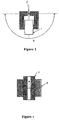
- an iron-cored electromagnet 1, or an assembly of permanent or trapped-flux magnets or other means providing a magnetic field is rotated about an axis 2 through the centre of the pole gap as shown, in which a suspension of HTSC particles is positioned or through which the suspension passes.
- the direction of the M1 alignment is determined by the direction of maximum average magnetic field magnitude.
- the magnet 1 may be initially held at this orientation to induce an initial uniaxial alignment.
- To induce a biaxial alignment the magnet is cyclically rotated, as indicated by arrow A, alternately to opposite positions through similar angles of greater than 0°, less than 180° and such as about 90°, with respect to the 0° position for short periods which are also short compared to typical grain orientation times. Rotations between 0° and only one other position such as the +90° position and back may be used.
- the body of HTSC particles may be rotated relative to the magnet.
- both field B1 and field B2 are produced by pulsed solenoids or coils 5 and 6.
- the M1 crystal axis aligns with the stronger pulsed or oscillating field B1 of coil 5 which has higher average magnitude, while coil 6 is pulsed with current to produce a pulsed or oscillating field in direction B2 of lower average magnitude so that the M2 axis of the HTSC crystals aligns along axis B2.
- the solenoid 5 may be pulsed to produce a field of similar strength but with a longer duty cycle so as to have a higher average field strength.
- the time varying field to which the crystals are subjected is the sum of the fields from the solenoids 5 and 6.
- a suspension of the HTSC is moved continuously or stepwise past a series of magnets alternately with field directions B1 and B2.
- the time spent in the B1 and B2 field regions and/or the relative strengths of the field in the B1 and B2 directions are controlled so that the average field strength in the B2 direction is less than the average field strength in the B1 direction, so that crystal axis M1 aligns with field axis B1 and crystal axis M2 aligns with field axis B2.
- a similar series of magnetic fields may also be produced by a succession of asymmetrically positioned core segments in a solenoid for example.
- the net field to which the HTSC is subjected as the HTSC moves past the magnets is a magnetic field the direction of which varies with time with an average magnitude which is a maximum in one direction lower in an orthogonal direction, and zero or minimum in a third direction orthogonal to the two other directions, which will again induce biaxial magnetic alignment.
- a powdered HTSC such as RBa 2 Cu 3 O 7-8 or R 2 Ba 4 Cu 7 O 15-8 , (where R is for Y or a rare earth element) may be dispersed with the aid of a suitable surfactant in a volatile fluid such as heptane, which is introduced to the inside of a container such as a tube or trough of silver, of sintered HTSC, or of ceramic with or without protective layers of materials selected for limited reactivity with the powdered HTSC.
- the tube or similar containing the dispersed HTSC may then be subjected to biaxial magnetic alignment according to the method of the invention.
- the tube is ventilated so that the suspension is able to dry after alignment has been achieved.
- a magnetic texture may be produced in which the b-axis is aligned along the tube length and the c-axis across the tube length, for example.
- a powdered HTSC may be suspended, optionally with the aid of a suitable surfactant, in a volatile fluid which is coated on the exterior of a substrate component such as metal tape which is then passed continuously through a region or zone in which the tape carrying the fluid suspending the HTSC particles is subjected to biaxial magnetic alignment by a time varying magnetic field according to the method of the invention, to biaxially texture the HTSC particles.
- the solvent may be evaporated to fix the aligned HTSC particles to the tape while maintaining their alignment, or may sediment through the thin solvent layer on the tape, or may be deposited on the tape by electrophoresis.
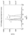
- FIG. 4a shows x-ray diffractometer traces measured on a sample of Dy-247 cured in epoxy while being rotated in a horizontal 1 T field. After being held several minutes stationary in the field the mould containing the sample was rotated successively about a vertical axis to orientations rotation -90°, 0°, +90° and 0° with respect to its original orientation. The dwell time at 0° was of order 2 seconds, at the transverse orientations half this time.
- the trace in Figure 4a labelled L shows the trace obtained on the sample face perpendicular to the field direction; the strong (oo l ) lines indicate c-axis texture.
- the traces labelled T and Z are for the surfaces respectively normal to the horizontal transverse direction and the vertical transverse direction. Any difference in these traces reveals a degree of biaxial alignment. Trace T is dominated by the (200) line, indicating a strong a-axis texture. Trace Z is dominated by the (020) line, indicating a strong b-axis texture. Figure 4b shows these lines in greater detail and Figure 4c shows the corresponding traces from a stationary sample which shows only uniaxial alignment. The biaxial texture obtained indicates that the magnitude of the susceptibility along the respective crystal axes reduces in the order CAB.
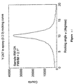
- the precise grain orientation attainable using biaxial magnetic alignment is demonstrated by the rocking curve for the (0 2 0) diffraction line of a Y-247 sample aligned in epoxy shown in Figure 4d. In this case the b-axis texture has a full width at half maximum of just over 2°.
- Biaxial alignment of Y-247 grains in epoxy was achieved using a rotating field apparatus with the sample remaining stationary.
- a magnetic field of 0.85 T was produced in a 10 mm gap using pairs of NdFeB permanent magnets mounted in a steel yoke rotatable about a horizontal axis. The field was alternated between horizontal and vertical orientations at frequencies around 0.5 Hz.
- the ratio of time spent in the major field (L) orientation to time spent in the perpendicular (T) orientation was typically 2:1.
- Field alternation was continued for several hours while the epoxy set.
- Figure 5 shows XRD traces recorded on mutually perpendicular surfaces with the L, Z, and T orientations as in Example 1, revealing a similar biaxial texture.
- the invention has been generally described with reference to the biaxial alignment of HTSC material but may also be used to induce biaxial crystalline alignment in other crystalline materials having anisotropic magnetic susceptibility.
Landscapes
- Engineering & Computer Science (AREA)
- Manufacturing & Machinery (AREA)
- Superconductors And Manufacturing Methods Therefor (AREA)
- Crystals, And After-Treatments Of Crystals (AREA)
- Compositions Of Oxide Ceramics (AREA)
- Physical Or Chemical Processes And Apparatus (AREA)
- Inorganic Compounds Of Heavy Metals (AREA)
- Superconductor Devices And Manufacturing Methods Thereof (AREA)
Description
Claims (7)
- A method of inducing biaxial particle alignment in a body of crystalline particles by subjecting the particles to a magnetic field, said crystalline particles having freedom to move to align with said magnetic field, so that at least a major portion of the crystalline particles have at least two crystalline axes generally parallel characterized by subjecting particles having anistropic magnetic susceptibility to repeated alternating cycles between a magnetic field (B1) in a first direction relative to the body of crystalline particles and a magnetic field (B2) in a second direction relative to the body of crystalline particles and which is orthogonal to said first direction, with the strength of said magnetic field in said first direction and the strength of said magnetic field in said second direction relative to one another, or the time for which the particles are subjected to said magnetic field in said first direction relative to the time for which the particles are subjected to said magnetic field in said second direction, being such that over said repeated alternating cycles between said magnetic field in said first direction and said magnetic field in said second direction, said magnetic field in said second direction has a lower average magnitude over time than the average magnitude over time of said magnetic field in said first direction, the resulting time varying field having a minimum or zero average magnitude in a third direction orthogonal to said first and second directions, to thereby induce alignment of the axis (M1) of maximum magnetic susceptibility of at least a major portion of the particles substantially with said field in said first direction, of an axis (M2) of lower magnetic susceptibility of the particles substantially with said field in said second direction, and of an axis (M3) of minimum magnetic susceptibility with said third direction.
- A method according to claim 1, comprising subjecting the particles to said repeated alternating cycles by causing cycles of relative rotation between the body of crystalline particles and a magnetic field so that the crystalline particles are subjected to the magnetic field in said first direction in one orientation between the body of crystalline particles and the magnetic field, and to the magnetic field in said second direction In another orientation between the body of crystalline particles and the magnetic field, and such that the body of crystalline particles is subjected to the magnetic field In said first direction for a time longer than the crystalline particles are subjected to the magnetic field in said second direction in each cycle.
- A method according to claim 2, comprising causing said relative rotation by cyclically rotating means (1) providing said magnetic field relative to the body of crystalline particles.
- A method according to claim 2, comprising causing said relative rotation by cyclically rotating said body of crystalline particles relative to said magnetic field.
- A method according to claim 1 comprising subjecting the particles to said repeated alternating cycles by creating said magnetic field in said first direction with a first electromagnet (5) and said field in said second direction with a second electromagnet (6) and pulsing said electromagnets alternately, and pulsing said first electromagnet for a time longer than said second electromagnet in each cycle or pulsing said first electromagnet so as to generate a magnetic field of higher strength than the magnetic field generated by said second electromagnet in each cycle.
- A method according to claim 1 comprising subjecting the particles to said repeated alternating cycles by causing relative transitional movement between the body of crystalline particles and a series of magnets oriented alternatively in said first and then said second directions.
- A method according to claim 6, wherein the body of crystalline particles is moved relative to said series of magnets
Applications Claiming Priority (3)
| Application Number | Priority Date | Filing Date | Title |
|---|---|---|---|
| NZ28016395 | 1995-10-03 | ||
| NZ28016395 | 1995-10-03 | ||
| PCT/NZ1996/000108 WO1997015067A2 (en) | 1995-10-03 | 1996-10-02 | A method of biaxially aligning crystalline material |
Publications (3)
| Publication Number | Publication Date |
|---|---|
| EP0853600A2 EP0853600A2 (en) | 1998-07-22 |
| EP0853600A4 EP0853600A4 (en) | 1999-03-24 |
| EP0853600B1 true EP0853600B1 (en) | 2003-06-25 |
Family
ID=19925494
Family Applications (1)
| Application Number | Title | Priority Date | Filing Date |
|---|---|---|---|
| EP96933675A Expired - Lifetime EP0853600B1 (en) | 1995-10-03 | 1996-10-02 | A method of biaxially aligning crystalline material |
Country Status (8)
| Country | Link |
|---|---|
| US (1) | US6399011B1 (en) |
| EP (1) | EP0853600B1 (en) |
| JP (1) | JPH11513655A (en) |
| AU (1) | AU7231096A (en) |
| CA (1) | CA2233616C (en) |
| DE (1) | DE69628842T2 (en) |
| NZ (1) | NZ319724A (en) |
| WO (1) | WO1997015067A2 (en) |
Families Citing this family (3)
| Publication number | Priority date | Publication date | Assignee | Title |
|---|---|---|---|---|
| JP2006097087A (en) * | 2004-09-29 | 2006-04-13 | Fuji Photo Film Co Ltd | Film deposition method and film deposition apparatus |
| JP2008036816A (en) * | 2004-10-21 | 2008-02-21 | Murata Mfg Co Ltd | Method for producing non-ferromagnetic material molded body, and non-ferromagnetic material molded body |
| US9831417B2 (en) * | 2011-10-14 | 2017-11-28 | Youtec Co., Ltd. | Poling treatment method, magnetic field poling device, and piezoelectric film |
Family Cites Families (6)
| Publication number | Priority date | Publication date | Assignee | Title |
|---|---|---|---|---|
| US5045528A (en) * | 1987-09-28 | 1991-09-03 | Arch Development Corporation | Acoustic plane wave preferential orientation of metal oxide superconducting materials |
| US4990493A (en) * | 1988-09-06 | 1991-02-05 | General Electric Company | Process of making an oriented polycrystal superconductor |
| US4939121A (en) * | 1988-10-20 | 1990-07-03 | General Dynamics Corporation, Electronics Division | Method and apparatus for inducing grain orientation by magnetic and electric field ordering during bulk superconductor synthesis |
| US5114905A (en) * | 1990-03-08 | 1992-05-19 | Northeastern University | Crystal alignment technique for superconductors |
| US5529981A (en) | 1992-03-05 | 1996-06-25 | Holloway; Alex | Process and apparatus for preparing biaxially textured materials using anisotropy in the paramagnetic susceptibility |
| US5280011A (en) | 1992-04-30 | 1994-01-18 | Northeastern University | Alignment technique for anisotropicly conductive crystals utilizing a non-static magnetic field |
-
1996
- 1996-10-02 US US09/051,156 patent/US6399011B1/en not_active Expired - Fee Related
- 1996-10-02 NZ NZ319724A patent/NZ319724A/en unknown
- 1996-10-02 DE DE69628842T patent/DE69628842T2/en not_active Expired - Fee Related
- 1996-10-02 AU AU72310/96A patent/AU7231096A/en not_active Abandoned
- 1996-10-02 EP EP96933675A patent/EP0853600B1/en not_active Expired - Lifetime
- 1996-10-02 WO PCT/NZ1996/000108 patent/WO1997015067A2/en not_active Ceased
- 1996-10-02 CA CA002233616A patent/CA2233616C/en not_active Expired - Fee Related
- 1996-10-02 JP JP9515722A patent/JPH11513655A/en not_active Ceased
Also Published As
| Publication number | Publication date |
|---|---|
| EP0853600A2 (en) | 1998-07-22 |
| CA2233616C (en) | 2003-07-08 |
| DE69628842D1 (en) | 2003-07-31 |
| US6399011B1 (en) | 2002-06-04 |
| AU7231096A (en) | 1997-05-07 |
| EP0853600A4 (en) | 1999-03-24 |
| WO1997015067A2 (en) | 1997-04-24 |
| WO1997015067A3 (en) | 1997-06-19 |
| NZ319724A (en) | 1998-08-26 |
| DE69628842T2 (en) | 2004-05-19 |
| CA2233616A1 (en) | 1997-04-24 |
| JPH11513655A (en) | 1999-11-24 |
Similar Documents
| Publication | Publication Date | Title |
|---|---|---|
| US6274022B1 (en) | Method for producing electro- or electroless-deposited film with a controlled crystal orientation | |
| US5079225A (en) | Process and apparatus for preparing textured crystalline materials using anisotropy in the paramagnetic susceptibility | |
| Tournier et al. | Texturing by cooling a metallic melt in a magnetic field | |
| Congreve et al. | Improvements in the processing of large grain, bulk Y–Ba–Cu–O superconductors via the use of additional liquid phase | |
| Aoki et al. | Single crystal growth of large-size and high-quality NpCoGa5 and its electrical and magnetic properties | |
| KR20040086911A (en) | Pure metal or alloy layer with biaxial texture electroplated on the surface of metal with crystal orientation similar to single crystal, manufacturing method thereof | |
| Mizutani et al. | Applications of superconducting permanent magnets driven by static and pulsed fields | |
| US6399011B1 (en) | Method of biaxially aligning crystalline material | |
| US5529981A (en) | Process and apparatus for preparing biaxially textured materials using anisotropy in the paramagnetic susceptibility | |
| KR100684224B1 (en) | Coating method of superconductor material using high residual magnetic induction, coated superconductor material and use thereof | |
| Ali et al. | Orientation degrees in Dy123 powders by using Linear-drive type Modulated Rotating Magnetic Field system | |
| Staines et al. | Thick film biaxially textured YBCO coated tape conductors prepared using magnetic grain alignment | |
| Alford et al. | Microstructural and magnetization studies of sintered and melt‐textured Y‐Ba‐Cu‐O | |
| JPH0782939B2 (en) | Magnet using oxide superconductor and method for manufacturing the same | |
| Somayazulu et al. | Direct observation of ferroelastic reorientation in single crystals of the superconductor Y Ba Cu O | |
| Lim et al. | Spin reorientation and first-order magnetization processes in (Er1− xTbx) 2Fe14B | |
| US5158930A (en) | Method of improving superconducting qualities of fabricated constructs by shock preprocessing of precursor materials | |
| Hu et al. | Bulk YBa2Cu3Ox superconductors through pressurized partial melt growth processing | |
| Takemura et al. | Yoke geometry study using pulsed field magnetization on superconducting joined bulk Gd-Ba-Cu-O | |
| Rillo et al. | Anisotropy in the diamagnetic properties of oriented Bi2Sr2CaCu2O8+ δ polycrystalline fibers | |
| Zhao | Improvement in the Growth and Superconducting Properties of Bulk Sm-Ba-Cu-O Superconductors Fabricated in Air | |
| US20020121630A1 (en) | Oxide superconductor | |
| JP2010006667A (en) | Oxide superconductive sintered body, and method for producing the same | |
| Shibata et al. | Magnetization reversal in SmCo5 single crystal | |
| HASHIMOTO et al. | H. TESHIMA, M. SAWAMURA and K. MIYAMOTO Advanced Materials & Technology Research Laboratories, Nippon Steel Corporation, 1618 Ida, Nakahara-ku, Kawasaki 211, Japan |
Legal Events
| Date | Code | Title | Description |
|---|---|---|---|
| PUAI | Public reference made under article 153(3) epc to a published international application that has entered the european phase |
Free format text: ORIGINAL CODE: 0009012 |
|
| 17P | Request for examination filed |
Effective date: 19980429 |
|
| AK | Designated contracting states |
Kind code of ref document: A2 Designated state(s): DE FR GB IT |
|
| A4 | Supplementary search report drawn up and despatched |
Effective date: 19990210 |
|
| AK | Designated contracting states |
Kind code of ref document: A4 Designated state(s): DE FR GB IT |
|
| 17Q | First examination report despatched |
Effective date: 20000706 |
|
| GRAH | Despatch of communication of intention to grant a patent |
Free format text: ORIGINAL CODE: EPIDOS IGRA |
|
| GRAH | Despatch of communication of intention to grant a patent |
Free format text: ORIGINAL CODE: EPIDOS IGRA |
|
| GRAH | Despatch of communication of intention to grant a patent |
Free format text: ORIGINAL CODE: EPIDOS IGRA |
|
| GRAA | (expected) grant |
Free format text: ORIGINAL CODE: 0009210 |
|
| AK | Designated contracting states |
Designated state(s): DE FR GB IT |
|
| PG25 | Lapsed in a contracting state [announced via postgrant information from national office to epo] |
Ref country code: IT Free format text: LAPSE BECAUSE OF FAILURE TO SUBMIT A TRANSLATION OF THE DESCRIPTION OR TO PAY THE FEE WITHIN THE PRE;WARNING: LAPSES OF ITALIAN PATENTS WITH EFFECTIVE DATE BEFORE 2007 MAY HAVE OCCURRED AT ANY TIME BEFORE 2007. THE CORRECT EFFECTIVE DATE MAY BE DIFFERENT FROM THE ONE RECORDED.SCRIBED TIME-LIMIT Effective date: 20030625 |
|
| REG | Reference to a national code |
Ref country code: GB Ref legal event code: FG4D |
|
| REF | Corresponds to: |
Ref document number: 69628842 Country of ref document: DE Date of ref document: 20030731 Kind code of ref document: P |
|
| PGFP | Annual fee paid to national office [announced via postgrant information from national office to epo] |
Ref country code: GB Payment date: 20030910 Year of fee payment: 8 |
|
| PGFP | Annual fee paid to national office [announced via postgrant information from national office to epo] |
Ref country code: FR Payment date: 20030918 Year of fee payment: 8 |
|
| PGFP | Annual fee paid to national office [announced via postgrant information from national office to epo] |
Ref country code: DE Payment date: 20031215 Year of fee payment: 8 |
|
| PLBE | No opposition filed within time limit |
Free format text: ORIGINAL CODE: 0009261 |
|
| STAA | Information on the status of an ep patent application or granted ep patent |
Free format text: STATUS: NO OPPOSITION FILED WITHIN TIME LIMIT |
|
| ET | Fr: translation filed | ||
| 26N | No opposition filed |
Effective date: 20040326 |
|
| PG25 | Lapsed in a contracting state [announced via postgrant information from national office to epo] |
Ref country code: GB Free format text: LAPSE BECAUSE OF NON-PAYMENT OF DUE FEES Effective date: 20041002 |
|
| PG25 | Lapsed in a contracting state [announced via postgrant information from national office to epo] |
Ref country code: DE Free format text: LAPSE BECAUSE OF NON-PAYMENT OF DUE FEES Effective date: 20050503 |
|
| GBPC | Gb: european patent ceased through non-payment of renewal fee |
Effective date: 20041002 |
|
| PG25 | Lapsed in a contracting state [announced via postgrant information from national office to epo] |
Ref country code: FR Free format text: LAPSE BECAUSE OF NON-PAYMENT OF DUE FEES Effective date: 20050630 |
|
| REG | Reference to a national code |
Ref country code: FR Ref legal event code: ST |