EP0853564B1 - Wiper blade for motor vehicle windshields - Google Patents
Wiper blade for motor vehicle windshields Download PDFInfo
- Publication number
- EP0853564B1 EP0853564B1 EP97923798A EP97923798A EP0853564B1 EP 0853564 B1 EP0853564 B1 EP 0853564B1 EP 97923798 A EP97923798 A EP 97923798A EP 97923798 A EP97923798 A EP 97923798A EP 0853564 B1 EP0853564 B1 EP 0853564B1
- Authority
- EP
- European Patent Office
- Prior art keywords
- supporting element
- wiper blade
- longitudinal
- longitudinal rails
- blade according
- Prior art date
- Legal status (The legal status is an assumption and is not a legal conclusion. Google has not performed a legal analysis and makes no representation as to the accuracy of the status listed.)
- Expired - Lifetime
Links
Images

Classifications
-
- B—PERFORMING OPERATIONS; TRANSPORTING
- B60—VEHICLES IN GENERAL
- B60S—SERVICING, CLEANING, REPAIRING, SUPPORTING, LIFTING, OR MANOEUVRING OF VEHICLES, NOT OTHERWISE PROVIDED FOR
- B60S1/00—Cleaning of vehicles
- B60S1/02—Cleaning windscreens, windows or optical devices
- B60S1/04—Wipers or the like, e.g. scrapers
- B60S1/32—Wipers or the like, e.g. scrapers characterised by constructional features of wiper blade arms or blades
- B60S1/38—Wiper blades
- B60S1/3848—Flat-type wiper blade, i.e. without harness
- B60S1/3849—Connectors therefor; Connection to wiper arm; Attached to blade
- B60S1/3851—Mounting of connector to blade assembly
- B60S1/3856—Gripping the blade
-
- B—PERFORMING OPERATIONS; TRANSPORTING
- B60—VEHICLES IN GENERAL
- B60S—SERVICING, CLEANING, REPAIRING, SUPPORTING, LIFTING, OR MANOEUVRING OF VEHICLES, NOT OTHERWISE PROVIDED FOR
- B60S1/00—Cleaning of vehicles
- B60S1/02—Cleaning windscreens, windows or optical devices
- B60S1/04—Wipers or the like, e.g. scrapers
- B60S1/32—Wipers or the like, e.g. scrapers characterised by constructional features of wiper blade arms or blades
- B60S1/38—Wiper blades
- B60S1/3848—Flat-type wiper blade, i.e. without harness
- B60S1/3874—Flat-type wiper blade, i.e. without harness with a reinforcing vertebra
- B60S1/3875—Flat-type wiper blade, i.e. without harness with a reinforcing vertebra rectangular section
- B60S1/3879—Flat-type wiper blade, i.e. without harness with a reinforcing vertebra rectangular section placed in side grooves in the squeegee
Definitions
- the invention is based on a wiper blade according to the Preamble of Claim 1.
- US-A-3,659,310 is a Wiper blade became known in which the contact pressure starting from the wiper arm on a bracket frame on a Wiper strip is transmitted.
- the wiper strip shows Supporting element that is made of special claws subordinate bracket of the bracket system is taken.
- Around the wiper strip, especially the support element simple It is proposed to be able to replace the support element to be hairpin-shaped and with an outer and an inner ramp and an external tooth structure in the Area of the inner ramp.
- With the inner The squeegee becomes a ramp in the support element by pressing the claw of the claw bracket acting from the outside.
- the outer ramp as well as the tooth structure are required around to keep the wiper strip inside the claw bracket.
- This Setup is complex and requires precise coordination of the outer ramp and the tooth structure by a certain To ensure mobility of the squeegee.
- Such a reduction in cross section can also be achieved by achieved a reduction in the thickness of the support element be, the greatest thickness in the central portion of the Supporting element is located.
- bracket of the trained stabilizer it may be appropriate be if these are non-positive or positive with the Longitudinal rails is connected. It goes without saying a powerful and fluid connection possible.
- the longitudinal extension of the support element exceeds a certain level, so that a certain Lability of the longitudinal rails may result in the required Stability of the support element can be ensured that between that at the free ends of the longitudinal rails arranged bracket and one the base of the hairpin shape forming web at least one additional intermediate bracket is arranged, which face away from each other Grips the longitudinal edges of the longitudinal rails with claw attachments.
- a further simplification of the wiper blade results if in an embodiment of the invention, the further bracket with a Connection device for the driven wiper arm Is provided.
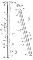
- FIG. 1 shows a side view of an inventive Wiper blade
- Figure 2 shows a section through the wiper blade along the line II - II in Figure 1, with a Perspective middle section of the wiper blade in an enlarged view
- Figure 3 shows a section through the Wiper blade along the line III - III in Figure 1, with a intermediate section shown in perspective
- in 4 shows the sectional area of an enlarged representation Cut through the wiper blade along the line IV - IV in Figure 1, in an enlarged view
- Figure 5 a perspective, to scale representation of a for Wiper blade supporting element and one to this belonging bracket.
- a wiper blade 10 shown in FIG. 1 has one elastic, in the embodiment made of spring steel manufactured support member 12 for one of a wiper strip 14 made of rubber-like material.
- Figure 1 is the elongated wiper blade 10 of the For simplicity, drawn in a position where it is can not be in practice because the elastic Support element is biased so that the wiper strip 14th is curved, as is by a dash-dotted line 16 is indicated in Figure 1.
- This curvature is stronger than the maximum curvature of the to be wiped, as a rule spherically curved motor vehicle window. It means that the wiper blade 10 when applied to the window to be wiped first with its two end areas on the disc Finally, the middle section of the plant also comes Wiper blade rests on the window.
- the Wiper strip 14 has a wiper lip that can be placed on the window 17, which is connected to the body 22 via a so-called tilting web 20 the wiper strip 14 is connected.
- longitudinal grooves 24 and 26 arranged, which extends over the entire length of the elongate wiper strip 14 extend.
- longitudinal rails 28 and 30 of the support element 12 housed, the structure of which can be seen from FIG.
- the support member 12 is made of one Spring band steel manufactured. It has its entire length a uniform thickness 34.
- the support member 12 has the shape a hairpin.
- the described hairpin shape of the support element 12 sees So before that the two longitudinal rails 28 and 30 parallel and are spaced from each other. It follows thus in the support member 12, a longitudinal slot 47 which in Area of the free ends of the longitudinal rails 28 and 30 opens.
- This mouth 48 enables easy assembly of the Wiper strip 14 and support element 12. To do this, only the Wiper strip 14 from the mouth 48 so on the support member 12 are pushed on that the two longitudinal rails 28 and 30 into the longitudinal grooves 24 and 26 of the wiper strip body 22 come to lie ( Figures 2 and 3). In doing so, the wiper strip 14 inserted into the support element up to the web 36. to Securing the wiper strip 14 on the support member 12 is on the free ends of the longitudinal strips 28 and 30 as Stabilizer acting clamp 50 applied.
- the clip 50 will cause some deformation of the wiper body 22 reached, which also a Securing the support element 12 on the wiper strip and a Securing the bracket 50 belonging to the support element 12 the wiper strip 14 is reached.
- it is also one positive locking of the clip 50 on the longitudinal rails 28, 30 and / or on the wiper strip 14 are conceivable.
- FIGS. 1 and 2 Another advantageous embodiment of the intermediate claws 60 can be seen from FIGS. 1 and 2.
Description
Die Erfindung geht aus von einem Wischblatt nach dem Oberbegriff des Anspruchs 1. Mit der US-A-3,659,310 ist ein Wischblatt bekannt geworden, bei dem der Anpreßdruck ausgehend vom Wischerarm über ein Tragbügelgestell auf eine Wischleiste übertragen wird. Die Wischleiste weist ein Tragelement auf, das von speziellen Krallen der untergeordneten Bügel des Tragbügelssystems gefaßt wird. Um die Wischleiste, insbesondere das Tragelement einfach austauschen zu können wird vorgeschlagen, das Tragelement haarnadelförmig auszugestalten und mit einer äußeren und einer inneren Rampe sowie mit einer äußeren Zahnstruktur im Bereich der inneren Rampe auszustatten. Mit der inneren Rampe wird der Wischgummi im Tragelement durch Einpressen der von außen wirkenden Kralle des Krallenbügels gehalten. Die äußere Rampe sowie die Zahnstruktur sind erforderlich um die Wischleiste innerhalb der Krallenbügel zu halten. Dieser Aufbau ist aufwendig und erfordert ein genaues Abstimmen der äußeren Rampe und der Zahnstruktur um eine gewisse Beweglichkeit des Wischgummis zu gewährleisten.The invention is based on a wiper blade according to the Preamble of Claim 1. US-A-3,659,310 is a Wiper blade became known in which the contact pressure starting from the wiper arm on a bracket frame on a Wiper strip is transmitted. The wiper strip shows Supporting element that is made of special claws subordinate bracket of the bracket system is taken. Around the wiper strip, especially the support element, simple It is proposed to be able to replace the support element to be hairpin-shaped and with an outer and an inner ramp and an external tooth structure in the Area of the inner ramp. With the inner The squeegee becomes a ramp in the support element by pressing the claw of the claw bracket acting from the outside. The outer ramp as well as the tooth structure are required around to keep the wiper strip inside the claw bracket. This Setup is complex and requires precise coordination of the outer ramp and the tooth structure by a certain To ensure mobility of the squeegee.
Bei einem anderen bekannten Wischblatt dieser Art (DE 26 14 457 A 1 oder US-A-3,192,551) ist das den Anpreßdruck des Wischblatts auf der Scheibe über die gesamte Länge der Wischleiste verteilende Tragelement mit einem schlitzartigen Längsdurchbruch versehen, durch welchen eine Längsrippe des Wischleistenkörpers von der einen Tragelementseite aus hindurchgreift wobei deren freies Ende so verdickt ist, daß es auf der anderen Seite eine Halterung oder Sicherung gegen unbeabsichtigtes Lösen der Wischleiste vom Tragelement bildet. Die Längsschienen des Tragelements kommen dabei in Längsnuten der Wischleiste zu liegen, welche an ihren Längsseiten einerseits durch den Körper der Wischleiste und andererseits durch die Verdickung der Längsrippe begrenzt sind. Zur Montage der Wischleiste am Tragelement muß die Wischleiste von Hand durch eine partielle Schlitzverbreiterung in dessen Längsschlitz eingefädelt werden, was aber sehr aufwendig und damit teuer ist. In another known wiper blade of this type (DE 26 14 457 A1 or US-A-3,192,551) is that Contact pressure of the wiper blade on the window over the entire Support element distributing the length of the wiper strip provided slot-like longitudinal opening through which a Longitudinal rib of the wiper body from one Support element side extends through with its free end is so thickened that there is a bracket on the other side or securing against unintentional loosening of the wiper strip forms from the support element. The longitudinal rails of the support element come to rest in the longitudinal grooves of the wiper strip, which on its long sides on the one hand through the body of the Wiper strip and on the other hand by thickening the Longitudinal rib are limited. For mounting the wiper strip on The wiper strip must be supported by a support element partial widening of the slot in its longitudinal slot be threaded, which is very complex and therefore expensive is.
Durch die haarnadelförmige Ausbildung des Tragelements ergibt sich eine offene Mündung des Längsschlitzes an dem einen Ende des Tragelements, die eine einfache, gegebenenfalls auch automatische Montage der Wischleiste am Tragelement ermöglicht. Auch die Anordnung und Befestigung der als Massenteil gefertigten Klammer an den freien Enden der Längsschienen kann mittels eines Montageautomaten erfolgen.Due to the hairpin-shaped design of the support element there is an open mouth of the longitudinal slot on the one end of the support element which is a simple, if necessary also automatic assembly of the wiper strip on Carrying element enables. The arrangement and attachment the mass-produced bracket at the free ends the longitudinal rails can be fitted using an automatic assembly machine respectively.
Besonders einfach und damit kostengünstig läßt sich eine Querschnittsverringerung des Tragelements erreichen, wenn diese durch eine Verringerung der Breite des Tragelements realisiert ist wobei sich die größte Breite im Mittelabschnitt des Tragelements befindet.One can be particularly simple and therefore inexpensive Achieve cross-sectional reduction of the support element if this by reducing the width of the support element is realized with the greatest width in Middle section of the support element is located.
Eine solche Querschnittsverringerung kann aber auch durch eine Verringerung der Dicke des Tragelements erreicht werden, wobei sich die größte Dicke im Mittelabschnitt des Tragelements befindet.Such a reduction in cross section can also be achieved by achieved a reduction in the thickness of the support element be, the greatest thickness in the central portion of the Supporting element is located.
Je nach Auswahl des Materials für die Klammer des ausgebildeten Stabilisierungsmittels kann es zweckmäßig sein, wenn diese kraftschlüssig oder formschlüssig mit den Längsschienen verbunden ist. Selbstverständlich ist auch eine kraft- und formflüssige Verbindung möglich.Depending on the choice of material for the bracket of the trained stabilizer, it may be appropriate be if these are non-positive or positive with the Longitudinal rails is connected. It goes without saying a powerful and fluid connection possible.
Für den Fall, daß die Längserstreckung des Tragelements ein bestimmtes Maß übersteigt, so daß sich eine gewisse Labilität der Längsschienen ergibt, kann die erforderliche Stabilität des Tragelements dadurch sicher gestellt werden, daß zwischen der an den freien Enden der Längsschienen angeordneten Klammer und einem die Basis der Haarnadelform bildenden Steg wenigstens eine weitere Zwischenklammer angeordnet ist, welche die voneinander abgewandten Längskanten der Längsschienen mit Krallenansätzen umgreift.In the event that the longitudinal extension of the support element exceeds a certain level, so that a certain Lability of the longitudinal rails may result in the required Stability of the support element can be ensured that between that at the free ends of the longitudinal rails arranged bracket and one the base of the hairpin shape forming web at least one additional intermediate bracket is arranged, which face away from each other Grips the longitudinal edges of the longitudinal rails with claw attachments.
Eine weitere Vereinfachung des Wischblatts ergibt sich, wenn in Ausgestaltung der Erfindung die weitere Klammer mit einer Anschlußvorrichtung für den angetriebenen Wischerarm ausgestattet ist.A further simplification of the wiper blade results if in an embodiment of the invention, the further bracket with a Connection device for the driven wiper arm Is provided.
Wenn zumindest die Längsschienen des Tragelements aus Federbandstahl hergestellt sind kann ein besonders niedrig bauendes Wischblatt erzielt werden, das gute Eigenschaften hinsichtlich der vor der Windschutzscheibe vorhandenen Strömungsverhältnisse der anströmenden Luft aufweist.If at least the longitudinal rails of the support element Spring band steel can be made particularly low building wiper blade that has good properties in terms of those in front of the windshield Has flow conditions of the incoming air.
Weitere Vorteile und Verbesserungen des Wischblatts sind der nachfolgenden Beschreibung eines Ausführungsbeispieles zu entnehmen, das anhand der Zeichnung erläutert wird.Further advantages and improvements of the wiper blade are the following description of an embodiment remove, which is explained with reference to the drawing.
Es zeigen Figur 1 eine Seitenansicht eines erfindungsgemäßen Wischblatts, Figur 2 einen Schnitt durch das Wischblatt entlang der Linie II - II in Figur 1, mit einem perspektivisch dargestellten Mittelabschnitt des Wischblatts in vergrößerter Darstellung, Figur 3 einen Schnitt durch das Wischblatt entlang der Linie III - III in Figur 1, mit einem perspektivisch dargestellten Zwischenabschnitt, in vergrößerter Darstellung, Figur 4 die Schnittfläche eines Schnitts durch das Wischblatt entlang der Linie IV - IV in Figur 1, in vergrößerter Darstellung und Figur 5 eine perspektivische, unmaßstäbliche Darstellung eines zum Wischblatt gehörenden Tragelements und einer zu diesem gehörenden Klammer.1 shows a side view of an inventive Wiper blade, Figure 2 shows a section through the wiper blade along the line II - II in Figure 1, with a Perspective middle section of the wiper blade in an enlarged view, Figure 3 shows a section through the Wiper blade along the line III - III in Figure 1, with a intermediate section shown in perspective, in 4 shows the sectional area of an enlarged representation Cut through the wiper blade along the line IV - IV in Figure 1, in an enlarged view and Figure 5 a perspective, to scale representation of a for Wiper blade supporting element and one to this belonging bracket.
Ein in Figur 1 dargestelltes Wischblatt 10 weist eine
elastisches, beim Ausführungsbeispiel aus Federbandstahl
hergestelltes Tragelement 12 für eine aus einem
gummiähnlichen Material gefertigte Wischleiste 14 auf. In
Figur 1 ist das langgestreckte Wischblatt 10 der
Einfachheithalber in einer Position gezeichnet, in der es
sich in der Praxis nicht befinden kann, weil das elastische
Tragelement so vorgespannt ist, daß die Wischleiste 14
gekrümmt ist, wie dies durch eine strichpunktierte Linie 16
in Figur 1 angedeutet ist. Diese Krümmung ist stärker als
die maximale Krümmung der zu wischenden, in der Regel
sphärisch gekrümmten Kraftfahrzeugscheibe. Das heißt, daß
das Wischblatt 10 beim Anlegen an die zu wischende Scheibe
zunächst mit seinen beiden Endbereichen an der Scheibe zur
Anlage kommt bis schließlich auch der Mittelbereich des
Wischblatts an der Scheibe anliegt. Die eben beschriebene
Krümmung des Tragelements 12 und damit des Wischblatts 10
soll, bei sorgfältiger Abstimmung, eine möglichst
gleichmäßige Verteilung des vom angetriebenen Wischerarm 18
bewirkten Anpreßdrucks gegen die Scheibe bewirken.A
Der allgemeine Aufbau des Wischblatts 10 soll nun im
folgenden anhand der Figuren 1 bis 3 erläutert werden. Die
Wischleiste 14 hat eine an der Scheibe anlegbare Wischlippe
17, die über einen sogenannten Kippsteg 20 mit dem Körper 22
der Wischleiste 14 verbunden ist. In den beiden einander
gegenüberliegenden Längsseiten des Wischleistenkörpers 22
sind einander gegenüberliegende Längsnuten 24 und 26
angeordnet, welche sich über die gesamte Länge der
langestreckten Wischleiste 14 erstrecken. In den Längsnuten
24 und 26 sind Längsschienen 28 und 30 des Tragelements 12
untergebracht, dessen Aufbau aus Figur 5 ersichtlich ist.
Beim Ausführungsbeispiel ist das Tragelement 12 aus einem
Federbandstahl hergestellt. Es hat über seine gesamte Länge
eine gleichmäßige Dicke 34. Das Tragelement 12 hat die Form
einer Haarnadel. Die beiden Längsschienen 28 und 30 bilden
dabei die Haarnadelschenkel, die an ihrem einen Ende durch
einen einstückig mit den beiden Längsschienen verbundenen
Steg 36 verbunden sind. Es ergibt sich somit ein
einstückiges Bauelement, dessen Breite durch die voneinander
abgewandten Längskanten 38 und 40 der Längsschienen 28 und
30 begrenzt ist. Die Ausbildung des Tragelements 12 ist so
getroffen, daß es in seinem Mittelabschnitt 42 eine größere
Breite 44 hat als die Breite 46 im Bereich der freien Enden
der Längsschienen 28, 30 bzw. des Steges 36. Somit ergibt
sich also eine Verringerung des Querschnitts der beiden
Längsschienen von dem Mittelbereich 42 aus zu den
Schienenenden hin. Diese Querschnittsverringerung kann aber
auch durch eine Verringerung der Dicke der Längsschienenbei
gleichbleibender oder bei sich verringernder Breite der
Längsschienen - erreicht werden.The general structure of the
Die beschriebene Haarnadelform des Tragelements 12 sieht
also vor, daß die beiden Längsschienen 28 und 30 parallel
und mit Abstand voneinander angeordnet sind. Es ergibt sich
somit in dem Tragelement 12 ein Längsschlitz 47, der im
Bereich der freien Enden der Längsschienen 28 und 30 mündet.
Diese Mündung 48 ermöglicht eine problemlose Montage der
Wischleiste 14 und Tragelement 12. Dazu muß lediglich die
Wischleiste 14 von der Mündung 48 her so auf das Tragelement
12 aufgeschoben werden, daß die beiden Längsschienen 28 und
30 in die Längsnuten 24 und 26 des Wischleistenkörpers 22 zu
liegen kommen (Figuren 2 und 3). Dabei wird die Wischleiste
14 bis zum Steg 36 in das Tragelement eingeschoben. Zur
Sicherung der Wischleiste 14 am Tragelement 12 ist auf die
freien Enden der Längsleisten 28 und 30 eine als
Stabilisierungsmittel wirkende Klammer 50 aufgebracht. Diese
als separates Bauelement ausgebildete Klammer 50 umgreift
einen Teil des Wischleistenkörpers 22 und untergreift mit
Krallenansätzen 52 die in den Längsnuten 24 und 26 liegenden
Längsschienen 28, 30 des Tragelements 12. Da durch die
Verringerung der Breite 44, 46 des Tragelements diese
Längsschienen im Bereich von deren freien Enden nicht mehr
aus den Längsnuten 24, 26 ragen, greifen die Krallenansätze
52 nicht direkt unter die Längsschienen sondern sie
untergreifen die unteren Wände 54 und 56 der Längsnuten 24
und 26, welche durch eine nutartige Längseinschnürung 58 des
Wischleistenkörpers 22 gebildet sind. Durch zielgerichtetes
Zusammendrücken der Klammer 50 wird eine gewisse Verformung
des Wischleistenkörpers 22 erreicht, wodurch auch eine
Sicherung des Tragelements 12 an der Wischleiste und eine
Sicherung der zum Tragelement 12 gehörenden Klammer 50 an
der Wischleiste 14 erreicht wird. Es ist jedoch auch eine
formschlüssige Sicherung der Klammer 50 an den Längsschienen
28, 30 und/oder an der Wischleiste 14 denkbar.The described hairpin shape of the
Wenn die Länge des Wischblatts 10 und damit auch die Länge
des haarnadelförmigen Tragelements 12 ein gewisses Maß
übersteigt kann es zweckmäßig sein, zwischen den freien
Enden der Längsschienen 28, 30 und dem die Basis der
Haarnadelform bildenden Steg 36 Zwischenklammern 60
anzuordnen, die in den Figuren 1 bis 3 mit der Bezugszahl 60
versehen sind. Die Ausführung dieser sogenannten
Zwischenklammern 60 entspricht im wesentlichen der schon
beschriebenen Ausführung der Endklammer 50. Da jedoch diese
Zwischenklammern im mittleren Bereich des Tragelements
angeordnet sind (Figur 1), in dem die voneinander
abgewandten Längskanten 38, 40 der Längsschienen aus den
Längsnuten 24, 26 ragen, können Krallenansätze 68 dieser
Zwischenklammern 60 die aus den Längsnuten ragenden
Längsleisten 62, 64 der Längsschienen 28, 30 direkt
umgreifen.If the length of the
Eine weitere, vorteilhafte Ausgestaltung der Zwischenkrallen
60 ist aus den Figuren 1 und 2 ersichtlich. Dort sind zwei
einander benachbarte Zwischenkrallen 60 zu einem einzigen
Bauteil zusammengefaßt, da sie durch eine
Anschlußvorrichtung 66 miteinander verbunden sind mit deren
Hilfe das Wischblatt 10 an dem angetriebenen Wischerarm 18
in an sich bekannter Weise lösbar befestigt werden kann.Another advantageous embodiment of the
Es versteht sich von selbst, daß die schon erwähnte Änderung
des Querschnitts der beiden Längsschienen 28, 30 bzw. des
Tragelements 12 von dessen Mittelabschnitt 42 ausgehend den
jeweiligen Gegebenheiten angepaßt werden muß, damit eine
ordnungsgemäße Verteilung des Anpreßdrucks über die gesamte
Wischblattlänge erreicht wird.It goes without saying that the change already mentioned
of the cross section of the two
Claims (9)
- Wiper blade (10) for windows/lens glasses of motor vehicles, having an elastic, elongated supporting element (12) for an elongated wiper strip (14) which consists of a flexible material, can be placed against the window/lens glass to be wiped and has, on its longitudinal sides, mutually opposite longitudinal grooves (24, 26) in which spaced apart longitudinal rails (28, 30) of the supporting element (12) lie, the said supporting element having the shape of a hair pin whose two limbs form the longitudinal rails (28, 30) and whose free ends are held together, in particular are connected to each other, by stabilizing means (50), characterized in that the stabilizing means (50) are designed as a separate component, in that the central section (42) has a connecting device (66) for a driven wiper arm (18), and in that the cross section of the two longitudinal rails is reduced from their central region towards the rail ends.
- Wiper blade according to Claim 1, characterized in that the cross-sectional reduction of the supporting element (12) is realized by a reduction of the width (44 and 46) of the supporting element, in which case the greatest width (44) is situated in the central section (42) of the supporting element (12).
- Wiper blade according to one of Claims 1 or 2, characterized in that the cross-sectional reduction of the supporting element (12) is realized by a reduction of the thickness (34) of the supporting element, in which case the greatest thickness (34) is situated in the central section (42) of the supporting element (12).
- Wiper blade according to one of Claims 1 to 3, characterized in that the stabilizing means are designed as clips (50) and are connected frictionally to the longitudinal rails (28, 30) of the supporting element (12).
- Wiper blade according to one of Claims 1 to 3, characterized in that the stabilizing means are designed as clips (50) and are connected in an interlocking manner to the longitudinal rails (28, 30) of the supporting element (12).
- Wiper blade according to one of Claims 1 to 5, characterized in that at least one intermediate clip (60) is arranged between the clip (50), which is arranged on the free ends of the longitudinal rails (28, 30), and a web (36) which forms the base of the hair-pin shape.
- Wiper blade according to Claim 6, characterized in that the clip (50 or 60) grips with claw-type projections (68) around the mutually remote longitudinal edges (38, 40) of the longitudinal rails (28, 30).
- Wiper blade according to one of Claims 6 or 7, characterized in that the intermediate clip (60) is provided with a connecting device (66) for the wiper arm (18).
- Wiper blade according to one of Claims 1 to 8, characterized in that the supporting element (12) is produced from spring band steel.
Applications Claiming Priority (3)
| Application Number | Priority Date | Filing Date | Title |
|---|---|---|---|
| DE19627114 | 1996-07-05 | ||
| DE1996127114 DE19627114A1 (en) | 1996-07-05 | 1996-07-05 | Wiper blade for windows of motor vehicles |
| PCT/DE1997/000947 WO1998001326A1 (en) | 1996-07-05 | 1997-05-10 | Wiper blade for motor vehicle windshields |
Publications (2)
| Publication Number | Publication Date |
|---|---|
| EP0853564A1 EP0853564A1 (en) | 1998-07-22 |
| EP0853564B1 true EP0853564B1 (en) | 2002-01-16 |
Family
ID=7799029
Family Applications (1)
| Application Number | Title | Priority Date | Filing Date |
|---|---|---|---|
| EP97923798A Expired - Lifetime EP0853564B1 (en) | 1996-07-05 | 1997-05-10 | Wiper blade for motor vehicle windshields |
Country Status (6)
| Country | Link |
|---|---|
| EP (1) | EP0853564B1 (en) |
| JP (1) | JPH11512994A (en) |
| CN (1) | CN1114538C (en) |
| DE (2) | DE19627114A1 (en) |
| ES (1) | ES2170952T3 (en) |
| WO (1) | WO1998001326A1 (en) |
Families Citing this family (15)
| Publication number | Priority date | Publication date | Assignee | Title |
|---|---|---|---|---|
| DE19856300A1 (en) * | 1998-12-07 | 2000-06-08 | Bosch Gmbh Robert | Wiper blade for windows of motor vehicles |
| DE19860644A1 (en) * | 1998-12-29 | 2000-07-06 | Bosch Gmbh Robert | Device for the articulated connection of a wiper blade for windows of motor vehicles with a wiper arm and method for producing this connection |
| DE19907629A1 (en) * | 1999-02-23 | 2000-08-24 | Bosch Gmbh Robert | Pivot-connection for windscreen wiper blade of motor vehicle has strip-type spring-elastic metal support rail to hold wiper strip and elastic plastic coupling element installed on upper side facing away from windscreen |
| DE19909971A1 (en) * | 1999-03-06 | 2000-09-07 | Bosch Gmbh Robert | Wiper blade for cleaning vehicle windows and method for mounting the wiper blade |
| DE10025708A1 (en) * | 2000-05-25 | 2001-11-29 | Bosch Gmbh Robert | Wiper blade for cleaning vehicle windows |
| DE10025706A1 (en) * | 2000-05-25 | 2001-11-29 | Bosch Gmbh Robert | Wiper blade for cleaning vehicle windows |
| DE10038992B4 (en) * | 2000-08-10 | 2015-10-08 | Valeo Auto-Electric Wischer Und Motoren Gmbh | wiper device |
| DE10043427B4 (en) * | 2000-09-04 | 2010-09-23 | Valeo Wischersysteme Gmbh | wiper device |
| DE10120467A1 (en) | 2001-04-26 | 2002-10-31 | Bosch Gmbh Robert | Wiper blade for cleaning windows, especially of motor vehicles |
| JP4202940B2 (en) * | 2003-06-13 | 2008-12-24 | アスモ株式会社 | Wiper blade |
| DE102008000708A1 (en) * | 2008-03-17 | 2009-09-24 | Robert Bosch Gmbh | wiper blade |
| CN101780790B (en) * | 2009-01-15 | 2011-06-22 | 张继鸿 | Windshield wiper capable of stabilizing scraping strip |
| PL2233375T3 (en) * | 2009-03-25 | 2014-07-31 | Unipoint Electric Mfg Co Ltd | Windshield wiper blade structure |
| EP2563627B1 (en) * | 2010-04-28 | 2018-06-06 | Federal-Mogul S.a. | Windscreen wiper device |
| CN112572359A (en) * | 2020-12-01 | 2021-03-30 | 贵阳万江航空机电有限公司 | Six-claw plastic framework wiper blade with length larger than 550mm |
Family Cites Families (5)
| Publication number | Priority date | Publication date | Assignee | Title |
|---|---|---|---|---|
| US3192551A (en) * | 1964-08-31 | 1965-07-06 | Walter D Appel | Windshield wiper blade assembly |
| US3659310A (en) * | 1970-06-03 | 1972-05-02 | Wypco Corp The | Spine piece for squeegee blades |
| IT1032660B (en) * | 1975-04-11 | 1979-06-20 | Arman Sas Di Dario Arman Ec | REED SUPPORT FOR WIPER BRUSHES IN WIPER SYSTEMS ON BOARD OF MOTOR VEHICLES IN GENERAL |
| DE3827875C2 (en) * | 1988-08-13 | 1999-05-12 | Teves Gmbh Alfred | Replacement wiper strip and assembly process |
| FR2716853B1 (en) * | 1994-03-01 | 1996-04-19 | Valeo Systemes Dessuyage | Wiper blade with improved means for longitudinal immobilization of the reinforcing squeegee. |
-
1996
- 1996-07-05 DE DE1996127114 patent/DE19627114A1/en not_active Withdrawn
-
1997
- 1997-05-10 EP EP97923798A patent/EP0853564B1/en not_active Expired - Lifetime
- 1997-05-10 ES ES97923798T patent/ES2170952T3/en not_active Expired - Lifetime
- 1997-05-10 CN CN97190852A patent/CN1114538C/en not_active Expired - Fee Related
- 1997-05-10 JP JP10504630A patent/JPH11512994A/en active Pending
- 1997-05-10 DE DE59706012T patent/DE59706012D1/en not_active Expired - Lifetime
- 1997-05-10 WO PCT/DE1997/000947 patent/WO1998001326A1/en active IP Right Grant
Also Published As
| Publication number | Publication date |
|---|---|
| ES2170952T3 (en) | 2002-08-16 |
| WO1998001326A1 (en) | 1998-01-15 |
| CN1114538C (en) | 2003-07-16 |
| DE59706012D1 (en) | 2002-02-21 |
| JPH11512994A (en) | 1999-11-09 |
| DE19627114A1 (en) | 1998-01-08 |
| EP0853564A1 (en) | 1998-07-22 |
| CN1197431A (en) | 1998-10-28 |
Similar Documents
| Publication | Publication Date | Title |
|---|---|---|
| EP0853566B1 (en) | Wiper blade for motor vehicle windshields | |
| EP0853565B1 (en) | Wiper blade for motor vehicle windshields | |
| EP1140586B1 (en) | Packaging unit for a vehicle windscreen wiper blade which is at least partly located therein | |
| EP0850163B1 (en) | Windshield wiper blade | |
| DE19833666B4 (en) | Wiper blade for windows of motor vehicles | |
| EP0624133B1 (en) | Blade assembly for wiping motor vehicle windscreens | |
| EP1547883B1 (en) | Wiper blade for cleaning vehicle windscreens | |
| EP1332075B1 (en) | Device for detachably and hingedly connecting a wiper blade for cleaning panes to a wiper arm | |
| EP0853564B1 (en) | Wiper blade for motor vehicle windshields | |
| EP0935546A1 (en) | Wiper blade for cleaning automobile windscreens | |
| EP1289804A1 (en) | Wiper blade for cleaning vehicle panes | |
| EP1289806A1 (en) | Wiper blade for cleaning screens in particular on motor vehicles | |
| WO2001002224A1 (en) | Wiper blade for the glass surfaces of motor vehicles with an elongated, spring-elastic support element | |
| DE10065014A1 (en) | Wiper device, in particular for windows of motor vehicles | |
| WO1997021569A1 (en) | Wiper blade assembly for motor vehicle windscreens | |
| EP0847346B1 (en) | Wiper blade with wind-deflecting surface for windshield wiper systems of motor vehicles | |
| DE4320637A1 (en) | Wiper blade with a multisection supporting-bow frame | |
| EP0816194B1 (en) | Vehicle windscreen wiper | |
| DE10228494A1 (en) | Windscreen wiper blade has mounting with two walls attached to its top, bolt fitting through bore in this into adapter fitted with swiveling catch and wiper arm fitting into channel in its top | |
| EP0930991A1 (en) | Wiper blade for cleaning motor vehicle windscreens | |
| EP0499829B1 (en) | Wiping arrangement for automobile vehicle windows | |
| DE10312979A1 (en) | Wiper blade for windscreens esp. of motor vehicles has airflow aperture between wiper lip and construction element to deflect air flow | |
| DE19959259B4 (en) | Wiper blade for cleaning windows on motor vehicles | |
| WO2002012035A1 (en) | Wiper device, especially for motor vehicles | |
| DE3423317C2 (en) | Wiper device for windows of motor vehicles |
Legal Events
| Date | Code | Title | Description |
|---|---|---|---|
| PUAI | Public reference made under article 153(3) epc to a published international application that has entered the european phase |
Free format text: ORIGINAL CODE: 0009012 |
|
| AK | Designated contracting states |
Kind code of ref document: A1 Designated state(s): DE ES FR GB IT |
|
| 17P | Request for examination filed |
Effective date: 19980715 |
|
| 17Q | First examination report despatched |
Effective date: 20000320 |
|
| GRAG | Despatch of communication of intention to grant |
Free format text: ORIGINAL CODE: EPIDOS AGRA |
|
| GRAG | Despatch of communication of intention to grant |
Free format text: ORIGINAL CODE: EPIDOS AGRA |
|
| GRAH | Despatch of communication of intention to grant a patent |
Free format text: ORIGINAL CODE: EPIDOS IGRA |
|
| GRAH | Despatch of communication of intention to grant a patent |
Free format text: ORIGINAL CODE: EPIDOS IGRA |
|
| GRAA | (expected) grant |
Free format text: ORIGINAL CODE: 0009210 |
|
| REG | Reference to a national code |
Ref country code: GB Ref legal event code: IF02 |
|
| AK | Designated contracting states |
Kind code of ref document: B1 Designated state(s): DE ES FR GB IT |
|
| REF | Corresponds to: |
Ref document number: 59706012 Country of ref document: DE Date of ref document: 20020221 |
|
| GBT | Gb: translation of ep patent filed (gb section 77(6)(a)/1977) |
Effective date: 20020406 |
|
| ET | Fr: translation filed | ||
| REG | Reference to a national code |
Ref country code: ES Ref legal event code: FG2A Ref document number: 2170952 Country of ref document: ES Kind code of ref document: T3 |
|
| PLBE | No opposition filed within time limit |
Free format text: ORIGINAL CODE: 0009261 |
|
| STAA | Information on the status of an ep patent application or granted ep patent |
Free format text: STATUS: NO OPPOSITION FILED WITHIN TIME LIMIT |
|
| 26N | No opposition filed | ||
| PGFP | Annual fee paid to national office [announced via postgrant information from national office to epo] |
Ref country code: GB Payment date: 20050425 Year of fee payment: 9 |
|
| PGFP | Annual fee paid to national office [announced via postgrant information from national office to epo] |
Ref country code: FR Payment date: 20050519 Year of fee payment: 9 |
|
| PGFP | Annual fee paid to national office [announced via postgrant information from national office to epo] |
Ref country code: ES Payment date: 20050531 Year of fee payment: 9 |
|
| PG25 | Lapsed in a contracting state [announced via postgrant information from national office to epo] |
Ref country code: GB Free format text: LAPSE BECAUSE OF NON-PAYMENT OF DUE FEES Effective date: 20060510 |
|
| PG25 | Lapsed in a contracting state [announced via postgrant information from national office to epo] |
Ref country code: ES Free format text: LAPSE BECAUSE OF NON-PAYMENT OF DUE FEES Effective date: 20060511 |
|
| PGFP | Annual fee paid to national office [announced via postgrant information from national office to epo] |
Ref country code: IT Payment date: 20060531 Year of fee payment: 10 |
|
| GBPC | Gb: european patent ceased through non-payment of renewal fee |
Effective date: 20060510 |
|
| REG | Reference to a national code |
Ref country code: FR Ref legal event code: ST Effective date: 20070131 |
|
| REG | Reference to a national code |
Ref country code: ES Ref legal event code: FD2A Effective date: 20060511 |
|
| PG25 | Lapsed in a contracting state [announced via postgrant information from national office to epo] |
Ref country code: FR Free format text: LAPSE BECAUSE OF NON-PAYMENT OF DUE FEES Effective date: 20060531 |
|
| PG25 | Lapsed in a contracting state [announced via postgrant information from national office to epo] |
Ref country code: IT Free format text: LAPSE BECAUSE OF NON-PAYMENT OF DUE FEES Effective date: 20070510 |
|
| PGFP | Annual fee paid to national office [announced via postgrant information from national office to epo] |
Ref country code: DE Payment date: 20130723 Year of fee payment: 17 |
|
| REG | Reference to a national code |
Ref country code: DE Ref legal event code: R119 Ref document number: 59706012 Country of ref document: DE |
|
| REG | Reference to a national code |
Ref country code: DE Ref legal event code: R119 Ref document number: 59706012 Country of ref document: DE Effective date: 20141202 |
|
| PG25 | Lapsed in a contracting state [announced via postgrant information from national office to epo] |
Ref country code: DE Free format text: LAPSE BECAUSE OF NON-PAYMENT OF DUE FEES Effective date: 20141202 |