EP0853324B1 - Set of switches with means of mutual locking - Google Patents
Set of switches with means of mutual locking Download PDFInfo
- Publication number
- EP0853324B1 EP0853324B1 EP97203971A EP97203971A EP0853324B1 EP 0853324 B1 EP0853324 B1 EP 0853324B1 EP 97203971 A EP97203971 A EP 97203971A EP 97203971 A EP97203971 A EP 97203971A EP 0853324 B1 EP0853324 B1 EP 0853324B1
- Authority
- EP
- European Patent Office
- Prior art keywords
- switch
- cables
- switches
- rocker
- rockers
- Prior art date
- Legal status (The legal status is an assumption and is not a legal conclusion. Google has not performed a legal analysis and makes no representation as to the accuracy of the status listed.)
- Expired - Lifetime
Links
- 230000007246 mechanism Effects 0.000 description 8
- 230000033001 locomotion Effects 0.000 description 5
- 239000000470 constituent Substances 0.000 description 2
- 238000010276 construction Methods 0.000 description 2
- 238000004873 anchoring Methods 0.000 description 1
- 230000005540 biological transmission Effects 0.000 description 1
- 230000000694 effects Effects 0.000 description 1
- 239000000725 suspension Substances 0.000 description 1
Images


Classifications
-
- H—ELECTRICITY
- H01—ELECTRIC ELEMENTS
- H01H—ELECTRIC SWITCHES; RELAYS; SELECTORS; EMERGENCY PROTECTIVE DEVICES
- H01H9/00—Details of switching devices, not covered by groups H01H1/00 - H01H7/00
- H01H9/20—Interlocking, locking, or latching mechanisms
- H01H9/26—Interlocking, locking, or latching mechanisms for interlocking two or more switches
- H01H9/262—Interlocking, locking, or latching mechanisms for interlocking two or more switches using flexible transmission elements, e.g. Bowden cable
-
- H—ELECTRICITY
- H01—ELECTRIC ELEMENTS
- H01H—ELECTRIC SWITCHES; RELAYS; SELECTORS; EMERGENCY PROTECTIVE DEVICES
- H01H9/00—Details of switching devices, not covered by groups H01H1/00 - H01H7/00
- H01H9/20—Interlocking, locking, or latching mechanisms
- H01H9/26—Interlocking, locking, or latching mechanisms for interlocking two or more switches
- H01H2009/267—Interlocking, locking, or latching mechanisms for interlocking two or more switches with interlocking of two out of three switches, e.g. two switches each connecting a power supply to a busbar and a bus coupling switch interlocked in such a way that the power supplies are never connected in parallel
-
- H—ELECTRICITY
- H01—ELECTRIC ELEMENTS
- H01H—ELECTRIC SWITCHES; RELAYS; SELECTORS; EMERGENCY PROTECTIVE DEVICES
- H01H3/00—Mechanisms for operating contacts
- H01H3/32—Driving mechanisms, i.e. for transmitting driving force to the contacts
- H01H3/36—Driving mechanisms, i.e. for transmitting driving force to the contacts using belt, chain, or cord
Definitions
- the invention relates to a set of switches with means of mutual locking comprising three switches, where each switch has actuation means connected via cables with locking means.
- the device for mechanically interlocking the three switches guarantees that the two feeds are not inadvertently connected together when they are both active and connected to the electrical plant.
- the first movable parts usually consisting of slides, guided for example by pins running in suitable slots, transmit the motion imposed by the actuation means to the second movable parts. This transmission takes place by virtue of guide channels. Channels made between the first movable parts. The geometries of these guide channels can be altered with the relative position of the movable parts.
- the objective of the present invention is to overcome the above-listed drawbacks of the prior art and to simplify and strengthen the construction of the device, by guaranteeing high reliability and free arrangement of the switches to be mutually locked.
- each switch has an elastically supported rocker, in that each rocker is operationally connected to a means of locking the corresponding switch, in that each switch has an actuation means connected to two ends of two cables, in that the free ends of the cables of the first switch extend to an arm of the rocker of the second switch and to the arm of the rocker of the third switch, in that the free ends of the cables of the second switch extend to the arm of the rocker of the first switch and to the arm of the rocker of the third switch, and in that the free ends of the cables of the third switch extend to the arm of the rocker of the second switch and to the arm of the rocker of the first switch.
- rockers are connected centrally to a spring fixed to the switch at the opposite end.
- actuation means of each switch are in operational connection with slides translating from the switch open position to the switch closed position and the translating slides are connected to Bowden type cables.
- the levers of the rockers are inserted freely into slots for access to the toggles of the locking means provided in the support plates.
- lever of the rockers has grooves in its terminal part.
- terminal part has inclined lips.
- the rockers For the purpose of connecting the means of elastic suspension to the rocker in such a way as to hold the arms of the rockers horizontal, the rockers have central holes to which the spring is connected.
- the Bowden cables connected to the arms of the rockers are arranged parallel to the slot for access to the toggles of the locking means.
- the cables are flexible and run in sheaths and have threaded terminals at their ends.
- the threaded terminals of the cables are screwed with adjustment to the arms of the rockers by means of clasps fixed to threaded nuts.
- the translating slides have a projection into which threaded terminals fixed to the ends of the cables are screwed with adjustment.
- a further advantage is inferable from the small number of components and from the easy mounting which brings about high robustness and extreme reliability, also because no special geometrical tolerance is required in the construction of the components and in the mutual arrangement during mounting.
- a further advantage consists moreover in the possibility of a free arrangement of the switches to be mutually locked.
- the devices 4 for mutual locking are present in a similar manner on each switch 1, 2, 3.
- the switch 2 has a plate 5 fixed to a lateral abutment 6 of the box.
- Toggles of a locking means which is indicated 20 as a whole, are provided beneath the rocker 8 and between the ends of the two cables 15, 16. This means 20 of locking the control for opening and closing the switch 2 is not in contact with the rocker 8, in the arrangement illustrated.
- a translating slide is also provided on the plate 5.
- This translating slide 23 is operationally connected with the toggles of an actuation means or indicator toggles placed in line with the translating slide 23 beneath the plate 5.
- the translating slide 23 is connected to a lever fixed to the main shaft of the control mechanism of the switch 2.
- the opposite end of the first cable 13 is connected to the rocker 7 of another switch, the first switch 1 in the arrangement illustrated.
- the opposite end of the second cable 17 is connected to the rocker 9 of the third switch 3.
- the cables 15, 18 connected to the translating slide 22 of the first switch 1 are connected, at the opposite end, in the case of the first cable 15, to the rocker 8 of the second switch 2 and in the case of the second cable 18 to the rocker 9, of the third switch 3.
- cables 14, 16, connected to the translating slide 24 of the third switch 3 have their opposite end connected, in the case of the first cable 14, to the rocker 8 of the second switch 2 and in the case of the second cable 16 to the rocker 7 of the first switch 1.
- the spring 10 is connected at the top to the projection 30 present on the plate 5 ( Figure 2).
- the opposite end of the spring 10 is connected by means of a grommet 31 to a central hole 32 of the rocker 8 ( Figure 3).
- the lower end of the arms 35, 36 of the rocker 8 have holes 37, 38 ( Figure 4).
- the ends of the cables 42, 43 are lodged in these holes 37, 38.
- threaded terminals 40, 41 fixed to the end of the cables 42, 43 are screwed into nuts 46 fixed to pins or grommets 45 inserted into the holes 37, 38 of the rocker 8.
- the cables 42, 43 are inserted so that they can run in sheaths 50 fixed at the end to a projection 51 provided on the plate 5 ( Figure 2).
- the housings 52, 53 for the fixing of the sheaths 50 are arranged on the projection 51 in such a way that the distance between the cables 42, 43 coincides with the width of the rocker 8.
- the housings 52, 53 are moreover arranged in such a way that the cables 42, 43 are parallel and vertical.
- the rocker 8 has a lever 60 orthogonal to the plane of the rocker 8 ( Figure 4). Two grooves 61, 62 are present laterally at the end of the lever 60.
- the terminal part 63 of the lever 60 has upwardly inclined lateral lips 64, 65.
- a projection 81 present on the plate 5 fixes the sheaths 50 by arranging the terminal parts 85, 86 of the cables 13, 17 parallel to one another.
- the terminal parts 85, 86 have threads.
- the terminal parts 85, 86 are connected to a projection 90 present on the translating slide 80, by means of threaded holes 91, 92.
- the translating slide 83 is connected to the toggles of the actuation means, through a slot 100 made in the plate 5.
- the lever 60 of the rocker 8 is arranged in the upper part of the slot 70 and is not in contact with the toggles 71 of the locking means.
- the lowering 128 of the toggles 71 of the locking means prevents the closure of the second switch 2.
- the adjustment is carried out in a manner appropriate for preventing the rocker 8 from interacting with the toggles 71 of the locking means, pivoting only through the closing of a switch 1, 3.
- the adjustment of the position of the rocker 8 in the slot 70 is carried out in such a way that when both switches 1, 3 close, the thrust of the lever 60 of the rocker 8 is sufficient to actuate the means of locking of the switch 2.
Landscapes
- Physics & Mathematics (AREA)
- Electromagnetism (AREA)
- Mechanical Control Devices (AREA)
- Switches With Compound Operations (AREA)
- Lock And Its Accessories (AREA)
- Mechanisms For Operating Contacts (AREA)
- Switch Cases, Indication, And Locking (AREA)
- Transmitters (AREA)
Description
- The invention relates to a set of switches with means of mutual locking comprising three switches, where each switch has actuation means connected via cables with locking means.
- Known means of actuation stretch the cables when passing from the switch open position to the switch closed position. Known means of locking, actuated by the cables, prevent closure of the switch.
- It is known that in an electrical plant consisting of two separately fed systems of bars, one switch is inserted into each system of bars. A third switch is inserted into a system of bars for linking the first two systems, and is normally open. In the event that one of the feeds fails, the switch, which connects this feed to the system of bars of the electrical plant, opens and the third switch, which connects the two systems of bars (or linking switch), closes connecting the remaining active feed to both systems of bars.
- The device for mechanically interlocking the three switches guarantees that the two feeds are not inadvertently connected together when they are both active and connected to the electrical plant.
- At present mechanical interlocking between three switches is carried out by connecting to known means of locking of known mechanisms. These mechanisms, present on each of the switches, are connected by first movable parts to the known means of actuation of the other switches via known flexible cables. Second movable parts of the mechanisms are connected to the known means of locking of the switch.
- The first movable parts, usually consisting of slides, guided for example by pins running in suitable slots, transmit the motion imposed by the actuation means to the second movable parts. This transmission takes place by virtue of guide channels. Channels made between the first movable parts. The geometries of these guide channels can be altered with the relative position of the movable parts.
- Only in the case in which two of the switches are simultaneously closed, these first movable parts, connected to them, restrict the guide channels in a manner appropriate for anchoring and dragging the second movable parts. In their turn these second movable parts transmit the motion to the switch locking mechanisms.
- These mechanisms are bulky, complex and made up of a large number of components. In particular these mechanisms are sensitive to the correct magnitude of the dimensional tolerance of the various parts for effecting functioning.
- Additionally, correct mounting of the components of the mechanism on the switch considerably influences functioning. An example of an electrical apparatus having backing means of the known type is described in
FR 2 624 647A. - The objective of the present invention is to overcome the above-listed drawbacks of the prior art and to simplify and strengthen the construction of the device, by guaranteeing high reliability and free arrangement of the switches to be mutually locked.
- The objectives of the invention are achieved by means of a set of switches with means of mutual locking, comprising a first, a second and a third switch in which each of the switches has actuation means connected via cables to locking means, characterized in that each switch has an elastically supported rocker, in that each rocker is operationally connected to a means of locking the corresponding switch, in that each switch has an actuation means connected to two ends of two cables, in that the free ends of the cables of the first switch extend to an arm of the rocker of the second switch and to the arm of the rocker of the third switch, in that the free ends of the cables of the second switch extend to the arm of the rocker of the first switch and to the arm of the rocker of the third switch, and in that the free ends of the cables of the third switch extend to the arm of the rocker of the second switch and to the arm of the rocker of the first switch.
- Advantageously the rockers are connected centrally to a spring fixed to the switch at the opposite end.
- With further advantage the actuation means of each switch are in operational connection with slides translating from the switch open position to the switch closed position and the translating slides are connected to Bowden type cables.
- To enable the rocker to interact with the toggles of the locking means, the levers of the rockers are inserted freely into slots for access to the toggles of the locking means provided in the support plates.
- Advantageously the lever of the rockers has grooves in its terminal part.
- With further advantage the terminal part has inclined lips.
- In order to connect the Bowden cables to the rockers, holes are provided at the end of the arms of the rockers.
- For the purpose of connecting the means of elastic suspension to the rocker in such a way as to hold the arms of the rockers horizontal, the rockers have central holes to which the spring is connected.
- To enable the translating Bowden cables to make the lever of the rockers run effortlessly in the slots present in the support plate, the Bowden cables connected to the arms of the rockers are arranged parallel to the slot for access to the toggles of the locking means. To guarantee a free arrangement in the electrical board of the three switches to be mutually locked, the cables are flexible and run in sheaths and have threaded terminals at their ends.
- To adjust the length of the cables which connect the actuation means with the locking means, the threaded terminals of the cables are screwed with adjustment to the arms of the rockers by means of clasps fixed to threaded nuts.
- Advantageously the translating slides have a projection into which threaded terminals fixed to the ends of the cables are screwed with adjustment.
- To prevent the sheaths in which the cables run from moving during the tensioning of the cables and to facilitate the motion of the translating slide, projections of the support plate to which are connected sheaths in which the cables run are provided opposite the translating slides and the cables are arranged parallel to the direction of run of the translating slides. The advantage of the present invention is to be perceived mainly in considerable constructional simplicity.
- A further advantage is inferable from the small number of components and from the easy mounting which brings about high robustness and extreme reliability, also because no special geometrical tolerance is required in the construction of the components and in the mutual arrangement during mounting.
- An advantage consists in the limited dimensions and ease of adjustment.
- A further advantage consists moreover in the possibility of a free arrangement of the switches to be mutually locked.
- The subject, devised according to the present invention, will be described below in greater detail and illustrated as an embodiment, given merely by way of example, in the appended drawings in which:
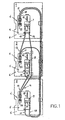
- Figure 1 illustrates, diagrammatically and in side view, three switches mutually connected by locking means;
- Figure 2 shows the detail of the second switch of Figure 1;
- Figure 3 illustrates the detail of a rocker mounted on a switch and not interacting with the toggles of the locking means;
- Figure 4 illustrates the rocker of Figure 3, seen from behind and axonometrically;
- Figures 5 and 6 show two positions of a translating slide connected to the means of actuation of a switch;
- Figures 7 and 8 illustrate two different positions of the rocker;
- Figure 9 illustrates a third position of the rocker in contact with the toggles of the locking means.
-
- Switches with means of mutual locking are of known design and functioning, so that only the parts essential to the invention will be described below.
- From Figure 1 may be observed a possible arrangement of three
switches - The
devices 4 for mutual locking are present in a similar manner on eachswitch - Therefore, the
device 4 for locking thesecond switch 2 will be described below by way of example. - The
switch 2 has aplate 5 fixed to alateral abutment 6 of the box. - Parallel to the
plate 5 there is arocker 8 supported centrally and at the top at the lower end of aspring 10. Thespring 10 is fixed, at the opposite end, to theplate 5. - The ends of two cables running in sheaths or Bowden cables, indicated 15 and 16 as a whole, are connected in a pivotable manner to the two arms of the
rocker 8. - Toggles of a locking means, which is indicated 20 as a whole, are provided beneath the
rocker 8 and between the ends of the twocables switch 2 is not in contact with therocker 8, in the arrangement illustrated. - A translating slide, indicated 23 as a whole, is also provided on the
plate 5. This translatingslide 23 is operationally connected with the toggles of an actuation means or indicator toggles placed in line with thetranslating slide 23 beneath theplate 5. For example, the translatingslide 23 is connected to a lever fixed to the main shaft of the control mechanism of theswitch 2. - The ends of two Bowden type cables, indicated 13 and 17 as a whole, are fixed to the translating
slide 23. - The opposite end of the
first cable 13 is connected to therocker 7 of another switch, thefirst switch 1 in the arrangement illustrated. - The opposite end of the
second cable 17 is connected to therocker 9 of thethird switch 3. - The
cables translating slide 22 of thefirst switch 1 are connected, at the opposite end, in the case of thefirst cable 15, to therocker 8 of thesecond switch 2 and in the case of thesecond cable 18 to therocker 9, of thethird switch 3. - Similarly the
cables third switch 3, have their opposite end connected, in the case of thefirst cable 14, to therocker 8 of thesecond switch 2 and in the case of thesecond cable 16 to therocker 7 of thefirst switch 1. - From Figures 2, 3, 4 and 5 it is possible to observe the constituent details of the device for mutual locking of the
second switch 2 and, particularly, the constituent details of therocker 8 and of the translatingslide 23. - The
spring 10 is connected at the top to theprojection 30 present on the plate 5 (Figure 2). - Advantageously, centrally to the
projection 30 there is a hole in which the grommet 31 of thespring 10 is inserted. - The opposite end of the
spring 10 is connected by means of a grommet 31 to acentral hole 32 of the rocker 8 (Figure 3). - The lower end of the
arms rocker 8 haveholes 37, 38 (Figure 4). The ends of thecables holes - Advantageously, threaded
terminals cables nuts 46 fixed to pins orgrommets 45 inserted into theholes rocker 8. - The
cables sheaths 50 fixed at the end to aprojection 51 provided on the plate 5 (Figure 2). - Advantageously the
housings sheaths 50, are arranged on theprojection 51 in such a way that the distance between thecables rocker 8. Thehousings cables - In the central and lower part the
rocker 8 has alever 60 orthogonal to the plane of the rocker 8 (Figure 4). Twogrooves lever 60. Theterminal part 63 of thelever 60 has upwardly inclinedlateral lips - In line with the
grooves rocker 8 is inserted, without contact, into avertical slot 60 made in the plate 5 (Figure 2 and 3). Theslot 70 is long enough to allow therocker 8, when it is arranged in the lower part of theslot 70, to bear with thrust by means of thelever 60 on thetoggles 71 of the means of locking of the switch 2 (Figure 9). - The ends of the
cables rockers - A
projection 81 present on theplate 5 fixes thesheaths 50 by arranging theterminal parts cables - The
terminal parts terminal parts projection 90 present on the translatingslide 80, by means of threadedholes - The translating slide 83 is connected to the toggles of the actuation means, through a
slot 100 made in theplate 5. - The functioning of the present invention will now be described with the help of Figures 6, 7, 8 and 9.
- Initially, when all three
switches rocker 8 is balanced pulled from above by thespring 10 and from below by thecables - In this arrangement, the
lever 60 of therocker 8 is arranged in the upper part of theslot 70 and is not in contact with thetoggles 71 of the locking means. - When, for example, only the
first switch 1 closes, the translatingslide 22 is lowered 110 pulling 115 thecables 15, 18 (Figure 6). Pulling 115 thecable 15, therocker 8 pivots 116 in the anticlockwise direction (Figure 7). Thelever 60 of therocker 8 is lowered running in theslot 70 without coming into contact with thelever 71 of the locking means. Thelever 60 of therocker 8 does not come into contact with thelever 71 of the locking means also because theterminal part 63 of thelever 60 has itslateral lips - In the case, on the other hand, in which only the
third switch 3 closes, the translating slide 24stretches 120 thecables rocker 8 to pivot 121 in the clockwise direction (Figures 1 and 8). - In the event that the
first switch 1 and also thethird switch 3 close, the means of actuation of theswitches cables cables hole 33 where therocker 8 is elastically supported. On account of the lowering of thecables movement 127 carries thelever 60 into contact with thetoggles 71 of the locking means and brings about a lowering 128 of thesetoggles 71. - The lowering 128 of the
toggles 71 of the locking means prevents the closure of thesecond switch 2. - In an entirely similar manner it is possible to effect the locking of the first switch I in the event that the second and the
third switch third switch 3 in the event that the first and thesecond switch - Advantageously, by virtue of the threaded
terminals cables slides 80 and on the means of fixing to therockers interlock devices 4. The adjustment acts on the tension of thecables springs 10 as well as on the position of balance of therockers - For example, by screwing the terminals into the threaded holes present on the projections of the translating slides 22, 24 of the
first switch 1 and of thethird switch 3, it is possible to lower therocker 8, by adjusting the position of thelever 60 inserted into theslot 70 of theplate 5. - The adjustment is carried out in a manner appropriate for preventing the
rocker 8 from interacting with thetoggles 71 of the locking means, pivoting only through the closing of aswitch rocker 8 in theslot 70 is carried out in such a way that when bothswitches lever 60 of therocker 8 is sufficient to actuate the means of locking of theswitch 2. - Advantageously the use of flexible cabling to transmit the motion from the actuation means to the locking means, makes it possible to arrange the switches in any mutual position whatsoever, facilitating the design of the electrical board.
Claims (13)
- Set of switches with means of mutual locking, comprising a first, a second and a third switch (1, 2, 3) in which each of the switches has actuation means connected via cables (13, 14, 15, 16, 17, 18) to locking means (19, 20, 21), characterized in that each switch (1, 2, 3) has an elastically supported rocker (7, 8, 9), in that each rocker (7, 8, 9) is operationally connected to a means (19, 20, 21) of locking the corresponding switch (1, 2, 3), in that each switch (1, 2, 3) has an actuation means connected to two ends of two cables (13, 14, 15, 16, 17), in that the free ends of the cables (15, 18) of the first switch (1) extend to an arm (35) of the rocker (8) of the second switch (2) and to the arm of the rocker (9) of the third switch (3), in that the free ends of the cables (13, 17) of the second switch (2) extend to the arm of the rocker (7) of the first switch (1) and to the arm of the rocker (9) of the third switch (3), and in that the free ends of the cables (16, 14) of the third switch (3) extend to the arm (36) of the rocker (8) of the second switch (2) and to the arm of the rocker (7) of the first switch (1).
- Set of switches, according to Claim 1, characterized in that the rockers (7, 8, 9) are connected centrally to a spring (10) fixed to the switch (1, 2, 3) at the opposite end.
- Set of switches, according to Claim 1, characterized in that the actuation means of each switch (1, 2, 3) are in operational connection with slides (22, 23, 24) translating from the switch open position to the switch closed position, in that the translating slides (22, 23, 24) are connected to Bowden type cables (15, 18, 13, 17, 16, 14).
- Set of switches according to Claim 1, characterized in that the levers (60) of the rockers (7, 8, 9) are inserted freely into slots (70) for access to the toggles (71) of the locking means (19, 20, 21) provided in the support plates (5).
- Set of switches, according to Claim 4, characterized in that the lever (60) of the rockers (7, 8, 9) has grooves (61, 62) in its terminal part (63).
- Set of switches, according to Claim 4, characterized in that the terminal part (63) has inclined lips (64, 65).
- Set of switches, according to Claim 1, characterized in that holes (37, 38) are provided at the end of the arms (35, 36) of the rockers (7, 8, 9).
- Set of switches, according to Claim 4, characterized in that the rockers (7, 8, 9) have central holes (33) to which the spring (10) is connected.
- Set of switches, according to Claim 4, characterized in that the Bowden cables (13, 14, 15, 16, 17, 18) connected to the arms (35, 36) of the rockers (7, 8, 9) are arranged parallel to the slot (70) for access to the toggles (71) of the locking means (19, 20, 21).
- Set of switches, according to Claim 1, characterized in that the cables (42, 43) are flexible and run in sheaths (50) and have threaded terminals (40, 41, 85, 86) at their ends.
- Set of switches, according to Claim 10, characterized in that the threaded terminals (40, 41) of the cables (42, 43) are screwed with adjustment to the arms (35, 36) of the rockers (7, 8, 9) by means of clasps (45) fixed to threaded nuts (46).
- Set of switches according to Claim 3, characterized in that the translating slides (22, 23, 24) have a projection (90) into which threaded terminals (85, 86) fixed to the ends of the cables (40, 41) are screwed with adjustment.
- Set of switches, according to Claim 3, characterized in that projections (81) of the support plate (5) to which are connected sheaths (50) in which the cables (40, 41) run are provided opposite the translating slides (22, 23, 24) and in that the cables (40, 41) are arranged parallel to the direction of run of the translating slides (22, 23, 24).
Applications Claiming Priority (2)
| Application Number | Priority Date | Filing Date | Title |
|---|---|---|---|
| IT96MI002686A IT1289481B1 (en) | 1996-12-20 | 1996-12-20 | SERIES OF SWITCHES WITH MUTUAL LOCKING MEANS |
| ITMI962686 | 1996-12-20 |
Publications (3)
| Publication Number | Publication Date |
|---|---|
| EP0853324A2 EP0853324A2 (en) | 1998-07-15 |
| EP0853324A3 EP0853324A3 (en) | 1999-01-27 |
| EP0853324B1 true EP0853324B1 (en) | 2003-09-03 |
Family
ID=11375446
Family Applications (1)
| Application Number | Title | Priority Date | Filing Date |
|---|---|---|---|
| EP97203971A Expired - Lifetime EP0853324B1 (en) | 1996-12-20 | 1997-12-17 | Set of switches with means of mutual locking |
Country Status (6)
| Country | Link |
|---|---|
| US (1) | US6060668A (en) |
| EP (1) | EP0853324B1 (en) |
| CN (1) | CN1075233C (en) |
| DE (1) | DE69724577T2 (en) |
| ES (1) | ES2206653T3 (en) |
| IT (1) | IT1289481B1 (en) |
Cited By (2)
| Publication number | Priority date | Publication date | Assignee | Title |
|---|---|---|---|---|
| DE102008007987B3 (en) * | 2008-02-07 | 2009-05-07 | Moeller Gmbh | Arrangement for locking switches |
| US8237070B2 (en) | 2006-07-03 | 2012-08-07 | Zhejiang Chint Electrics Co., Ltd. | Set of circuit breakers with interlock means |
Families Citing this family (6)
| Publication number | Priority date | Publication date | Assignee | Title |
|---|---|---|---|---|
| FR2789511B1 (en) * | 1999-02-08 | 2001-05-04 | Schneider Electric Ind Sa | INSTALLATION COMPRISING AN ELECTRICAL SWITCHING APPARATUS AND A CABLE INTERLOCK |
| US6388214B1 (en) * | 2000-11-03 | 2002-05-14 | Eaton Corporation | Mechanical and gate for interlocking electric power switches and distribution system incorporating same |
| WO2012117270A1 (en) | 2011-03-01 | 2012-09-07 | Larsen & Toubro Limited | An improved interlock system for switching devices |
| KR101910388B1 (en) * | 2017-04-11 | 2018-10-22 | 엘에스산전 주식회사 | Interlock apparatus of circuit breaker |
| CN107578964B (en) * | 2017-10-25 | 2018-11-23 | 谢志坚 | A kind of mechanical interlocks for air-break circuit-breaker |
| CN107908137B (en) * | 2017-12-04 | 2019-06-28 | 常熟开关制造有限公司(原常熟开关厂) | Electrical interlocking control device and its control method, automatic change-over |
Family Cites Families (6)
| Publication number | Priority date | Publication date | Assignee | Title |
|---|---|---|---|---|
| US2904649A (en) * | 1957-08-22 | 1959-09-15 | Cutler Hammer Inc | Mechanical interlock for circuit breakers |
| FR2624647A1 (en) * | 1987-12-14 | 1989-06-16 | Merlin Gerin | INTERLOCKING A PLURALITY OF CIRCUIT BREAKERS |
| US5466902A (en) * | 1993-11-23 | 1995-11-14 | Abb Power T&D Company Inc. | Switch operator and interlock mechanism |
| DE4439746C1 (en) * | 1994-10-31 | 1996-04-04 | Siemens Ag | Evaluation device for a system for interlocking circuit breakers |
| US5726401A (en) * | 1996-03-29 | 1998-03-10 | Siemens Energy & Automation, Inc. | Cable/crossbar interlock system for circuit breakers |
| US5814777A (en) * | 1996-03-29 | 1998-09-29 | Siemens Energy & Automation,Inc. | Cable interlock system for circuit breakers |
-
1996
- 1996-12-20 IT IT96MI002686A patent/IT1289481B1/en active IP Right Grant
-
1997
- 1997-12-17 EP EP97203971A patent/EP0853324B1/en not_active Expired - Lifetime
- 1997-12-17 DE DE69724577T patent/DE69724577T2/en not_active Expired - Lifetime
- 1997-12-17 ES ES97203971T patent/ES2206653T3/en not_active Expired - Lifetime
- 1997-12-18 US US08/993,042 patent/US6060668A/en not_active Expired - Lifetime
- 1997-12-22 CN CN97125954A patent/CN1075233C/en not_active Expired - Fee Related
Cited By (3)
| Publication number | Priority date | Publication date | Assignee | Title |
|---|---|---|---|---|
| US8237070B2 (en) | 2006-07-03 | 2012-08-07 | Zhejiang Chint Electrics Co., Ltd. | Set of circuit breakers with interlock means |
| DE102008007987B3 (en) * | 2008-02-07 | 2009-05-07 | Moeller Gmbh | Arrangement for locking switches |
| US8692143B2 (en) | 2008-02-07 | 2014-04-08 | Eaton Industries Gmbh | Cable interlock between power switches |
Also Published As
| Publication number | Publication date |
|---|---|
| HK1011239A1 (en) | 1999-07-09 |
| EP0853324A2 (en) | 1998-07-15 |
| DE69724577T2 (en) | 2004-07-01 |
| CN1075233C (en) | 2001-11-21 |
| EP0853324A3 (en) | 1999-01-27 |
| IT1289481B1 (en) | 1998-10-15 |
| DE69724577D1 (en) | 2003-10-09 |
| ES2206653T3 (en) | 2004-05-16 |
| ITMI962686A1 (en) | 1998-06-20 |
| US6060668A (en) | 2000-05-09 |
| CN1185640A (en) | 1998-06-24 |
Similar Documents
| Publication | Publication Date | Title |
|---|---|---|
| KR960015123B1 (en) | Enclosed switchboard | |
| US6060668A (en) | Set of switches with means of mutual locking | |
| US4902859A (en) | Circuit breaker mechanical interlock | |
| US10622177B2 (en) | Switching device | |
| EP2040277B1 (en) | Circuit breaker assembly with interlocking device | |
| WO2007092859A1 (en) | Method and apparatus for control contacts of an automatic transfer switch | |
| JPH01286270A (en) | Conductor connector | |
| US5912444A (en) | Switch racking mechanism with interlock | |
| US6031191A (en) | Sliding frame with a break contact arrangement | |
| CN112943019A (en) | Device for moving a door leaf | |
| JP2015530334A (en) | Elevator closing confirmation device | |
| CN1318857A (en) | Mechanical tripping cam for circuit breaker | |
| EP3140846B1 (en) | Moulded case circuit breaker and method for assembling the same | |
| US8692143B2 (en) | Cable interlock between power switches | |
| US5294903A (en) | Electric switch, in particular a load switch or electric circuit breaker | |
| US2902555A (en) | Shutter control for bus duct plug-in unit | |
| AU602777B2 (en) | Circuit-breaker | |
| KR19980063818A (en) | Electrical contact connector | |
| EP0882300B1 (en) | Interlock arrangement for stationary mounted circuit breakers | |
| US6239395B1 (en) | Auxiliary position switch assembly for a circuit breaker | |
| KR102582142B1 (en) | Fixing Equipment for Overhead Line | |
| EP0560445A1 (en) | An adapter | |
| US20110122550A1 (en) | Partitioning device for mv cubicles | |
| EP0322986B1 (en) | Switch, in particular for use as automatic switch | |
| DE9103116U1 (en) | Device for controlling a lifting device |
Legal Events
| Date | Code | Title | Description |
|---|---|---|---|
| PUAI | Public reference made under article 153(3) epc to a published international application that has entered the european phase |
Free format text: ORIGINAL CODE: 0009012 |
|
| AK | Designated contracting states |
Kind code of ref document: A2 Designated state(s): DE ES FR GB IT |
|
| AX | Request for extension of the european patent |
Free format text: AL;LT;LV;MK;RO;SI |
|
| PUAL | Search report despatched |
Free format text: ORIGINAL CODE: 0009013 |
|
| AK | Designated contracting states |
Kind code of ref document: A3 Designated state(s): AT BE CH DE DK ES FI FR GB GR IE IT LI LU MC NL PT SE |
|
| AX | Request for extension of the european patent |
Free format text: AL;LT;LV;MK;RO;SI |
|
| 17P | Request for examination filed |
Effective date: 19990723 |
|
| AKX | Designation fees paid |
Free format text: DE ES FR GB IT |
|
| RAP1 | Party data changed (applicant data changed or rights of an application transferred) |
Owner name: ABB SACE LOW VOLTAGE SPA |
|
| RAP1 | Party data changed (applicant data changed or rights of an application transferred) |
Owner name: ABB SACE SPA |
|
| 17Q | First examination report despatched |
Effective date: 20020710 |
|
| GRAH | Despatch of communication of intention to grant a patent |
Free format text: ORIGINAL CODE: EPIDOS IGRA |
|
| GRAS | Grant fee paid |
Free format text: ORIGINAL CODE: EPIDOSNIGR3 |
|
| GRAA | (expected) grant |
Free format text: ORIGINAL CODE: 0009210 |
|
| AK | Designated contracting states |
Kind code of ref document: B1 Designated state(s): DE ES FR GB IT |
|
| REG | Reference to a national code |
Ref country code: GB Ref legal event code: FG4D |
|
| REF | Corresponds to: |
Ref document number: 69724577 Country of ref document: DE Date of ref document: 20031009 Kind code of ref document: P |
|
| REG | Reference to a national code |
Ref country code: ES Ref legal event code: FG2A Ref document number: 2206653 Country of ref document: ES Kind code of ref document: T3 |
|
| ET | Fr: translation filed | ||
| PLBE | No opposition filed within time limit |
Free format text: ORIGINAL CODE: 0009261 |
|
| STAA | Information on the status of an ep patent application or granted ep patent |
Free format text: STATUS: NO OPPOSITION FILED WITHIN TIME LIMIT |
|
| 26N | No opposition filed |
Effective date: 20040604 |
|
| PGFP | Annual fee paid to national office [announced via postgrant information from national office to epo] |
Ref country code: GB Payment date: 20101221 Year of fee payment: 14 |
|
| PGFP | Annual fee paid to national office [announced via postgrant information from national office to epo] |
Ref country code: ES Payment date: 20101223 Year of fee payment: 14 |
|
| REG | Reference to a national code |
Ref country code: ES Ref legal event code: FD2A Effective date: 20130703 |
|
| PG25 | Lapsed in a contracting state [announced via postgrant information from national office to epo] |
Ref country code: ES Free format text: LAPSE BECAUSE OF NON-PAYMENT OF DUE FEES Effective date: 20111218 |
|
| GBPC | Gb: european patent ceased through non-payment of renewal fee |
Effective date: 20121217 |
|
| PG25 | Lapsed in a contracting state [announced via postgrant information from national office to epo] |
Ref country code: GB Free format text: LAPSE BECAUSE OF NON-PAYMENT OF DUE FEES Effective date: 20121217 |
|
| REG | Reference to a national code |
Ref country code: FR Ref legal event code: PLFP Year of fee payment: 19 |
|
| REG | Reference to a national code |
Ref country code: FR Ref legal event code: PLFP Year of fee payment: 20 |
|
| PGFP | Annual fee paid to national office [announced via postgrant information from national office to epo] |
Ref country code: DE Payment date: 20161213 Year of fee payment: 20 |
|
| PGFP | Annual fee paid to national office [announced via postgrant information from national office to epo] |
Ref country code: FR Payment date: 20161222 Year of fee payment: 20 |
|
| PGFP | Annual fee paid to national office [announced via postgrant information from national office to epo] |
Ref country code: IT Payment date: 20161223 Year of fee payment: 20 |
|
| REG | Reference to a national code |
Ref country code: DE Ref legal event code: R071 Ref document number: 69724577 Country of ref document: DE |