EP0852839B1 - Plastic junction box with receptacle boxes - Google Patents
Plastic junction box with receptacle boxes Download PDFInfo
- Publication number
- EP0852839B1 EP0852839B1 EP96932302A EP96932302A EP0852839B1 EP 0852839 B1 EP0852839 B1 EP 0852839B1 EP 96932302 A EP96932302 A EP 96932302A EP 96932302 A EP96932302 A EP 96932302A EP 0852839 B1 EP0852839 B1 EP 0852839B1
- Authority
- EP
- European Patent Office
- Prior art keywords
- junction box
- housing
- box
- receptacle
- outlets
- Prior art date
- Legal status (The legal status is an assumption and is not a legal conclusion. Google has not performed a legal analysis and makes no representation as to the accuracy of the status listed.)
- Expired - Lifetime
Links
Images


Classifications
-
- H—ELECTRICITY
- H02—GENERATION; CONVERSION OR DISTRIBUTION OF ELECTRIC POWER
- H02G—INSTALLATION OF ELECTRIC CABLES OR LINES, OR OF COMBINED OPTICAL AND ELECTRIC CABLES OR LINES
- H02G3/00—Installations of electric cables or lines or protective tubing therefor in or on buildings, equivalent structures or vehicles
- H02G3/02—Details
- H02G3/08—Distribution boxes; Connection or junction boxes
- H02G3/18—Distribution boxes; Connection or junction boxes providing line outlets
- H02G3/185—Floor outlets and access cups
Definitions
- This invention relates generally to an insulated junction box that organizes and provides access to electrical, data or telecommunications cables or other service lines that are routed through channels formed between a false floor that is supported above an existing floor.
- Such false floors or raised panel floors typically utilize removable panels laid side-by-side upon raised support members in order to afford a free space where conduit, cables, hoses, wires and other computer interconnections can be routed.
- Many false flooring systems use adjustable jacks at each panel corner as a means of support.
- the support jacks for such systems are located only at the corners of the panels, which are usually square with sides of 500 to 600 mm. Accordingly, rigidity and mechanical stability of the floor must be achieved through the use of very thick panels, usually 30 to 40 mm thick, sometimes including a framework which transfers the load to the jacks.
- U.S. Patent No. 5,263,289 to Boyd discloses a box, which must be embedded into the structural floor, for providing service connection points.
- U.S. Patent No. 4,968,855 to Le Paillier discloses a "distribution slab" for wiring buildings.
- One embodiment illustrates a slab in which the outlets face upwards, thus requiring that spacing within the channels created between the base and lids be increased where bulky connection devices or plugs will be utilized.
- Another embodiment places outlets within one or more lids that can be raised or lowered. When the lid is lowered the outlets are inaccessible; however, when it is raised, while accessible, outlets are exposed to the environment and the raised lid and outlet becomes a hazard to those traveling the false floor.
- U.S. Patent No. 5,057,647 to Bogden, et al. discloses a "distribution block" that inserts into one of four compatibly shaped knockouts disposed in each corner of a floor plate. Once the appropriate knockout is removed, the distribution block inserts into the knockout and connects with modular electrical "whips" composed of electrical wires and end connectors. Electrical socket outlets and a cover plate are then fixed into the distribution block so that the outlets are exposed. Because the knockouts are formed in flooring plates through perforations, once the perforations are ruptured and the knockout plate removed, there is no means for replacing the knockout. Accordingly, in order to change the position of an already installed distribution block, not only must the block be laboriously unfastened, but the entire floor panel would need to be removed and replaced.
- U.S. Patent No. 5,362,922 to Whitehead discloses an electrical floor box in the general shape of a Greek cross, having a substantially square central portion, the arms of the cross defining cells extending outwardly from each side of the central portion.
- a plastic divider fits in the central portion and rests on the bottom of the box.
- a device cover plate extends down to fit into grooves on the divider and forms a cell above and to the side of the divider.
- a top plate covers the open top of each cell while leaving the central area open.
- Whitehead does not show tracks formed on the inside of a receptacle box or a frame comprising a central aperture that is capable of accepting a cable connector means for insertion into the tracks.
- Whitehead's electrical floor box is not described for use with a false floor; nor does Whitehead disclose means for contacting a selected group of standoffs to solve the technical problem of positioning the junction box laterally within a false floor without the need for additional fixing means.
- metal junction boxes present numerous benefits. Because such junction boxes conduct electricity, however, in certain applications short circuits can result from contact between wires or cables within or near such boxes and the boxes. Additionally, metal junction boxes can be difficult to make water-resistant or waterproof, and can be expensive to manufacture and install.
- junction box pass Standard IP 2.4.7 so that the associated certificate of approval can be obtained.
- This International Protection standard involves part 2, involving protection against a water "shower” of ten minutes applied to an installed and closed junction box, part 4, involving a safety standard for accessibility, and part 7, which is a standard for strength.
- the junction box of the present invention may include a centrally located housing having a bottom and four sides joined to form a square.
- One or two receptacle boxes also having bottoms are attached to each side of the square to provide housings for outlets and the cable and wire connections to such outlets.
- the outlets are accessible to the centrally located housing so that plugs may be positioned within the housing and received in the outlets.
- a cover lies above the outlet boxes and provides access to the outlets within the housing through a central hatch or opening in the cover.
- a junction box manufactured in accordance with the present invention is capable of obtaining certification under IP 2.4.7.
- the housing and cover may be formed from a variety of plastic materials, particularly including molded polypropylene, but also including polystyrene, polyethylene, ABS or PVC.
- the junction box acts as an interface between (1) the electrical, telecommunication, data or other service lines traveling through channels formed beneath a false floor and (2) the equipment resting upon the false floor that must connect to the correct service line.
- Various outlets within the junction box may be provided for electrical, telecommunication or data transmission lines of the flush or forward type or may be pierced with holes for passage of lines through the junction box directly to a specific piece of equipment.
- the central housing and outlet boxes preferably are fabricated as a single unit but also can be assembled from several components into various shapes, but preferably a square or cruciform, all of which fit tightly between and around the stand-offs supporting a false floor. No special fasteners or other attachment means need be used, as frictional contact between cutouts in a flange or ledge running along the top of the housing and stand-offs will fix the housing in place.
- a junction box can be placed at virtually any point in the area covered by a false floor. Accordingly, not only is flexibility of position greatly enhanced, but the junction box readily can be concealed in less traveled areas (e.g., underneath equipment or furniture), yet be conveniently close to equipment so that ready access to outlets within the junction box is provided.
- the sides of the housing may include a plurality of standard notches, channels or slots.
- Frames formed of plastic or some other, preferably dielectric, material may then be used with particular components or with particular suppliers' components.
- Each frame may simply slide into and be captured between a pair of opposed notches and thus held in place forming one wall of a receptacle box. The correctly sized cutout for a particular receptacle can be formed in each frame.
- a variety of frames with different sized component openings can be provided as an installation package to the installer, who will select the proper frame, snap the desired component into place in the frame and slide the frame into the proper notch or hole in the housing.
- the installer who will select the proper frame, snap the desired component into place in the frame and slide the frame into the proper notch or hole in the housing.
- An additional feature of the present invention is a hatch cover shaped to cover the access aperture within the cover, thereby ensuring foreign objects do not enter the junction box, possibly to damage the outlets or cables within, while preventing the junction box from becoming a hazard to persons or objects traveling upon the false floor.
- the hatch cover can be covered with the same carpet or other covering that is used on the flooring plates, thus concealing better the junction box from passers by.
- a small cable protector in the hatch cover allows it to be fully closed while still providing an egress for one or more cables entering the junction box and connecting to the outlets.
- junction boxes according to this invention may be fabricated to match the heights and shapes of the posts which support the false floor in which the junction box is used or to fit between the studs in a wall. Additionally, junction boxes can be fabricated to the length and shape required to engage with the desired number of posts to obtain thereby the desired size of junction box. More or fewer outlets can be provided within a junction box depending on the number of cables needed to be organized and accessed.
- FIG. 1 is a perspective view of the top and one side of the junction box of the present invention.
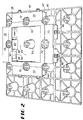
- FIG. 2 is a perspective view of the junction box shown in FIG. 1 shown in position on a system of low profile raised flooring stand-off supports.
- FIG. 3 is a perspective view similar to FIG. 2 with the junction box cover removed.
- FIG. 4 is a top plan view of the housing of the junction box of the present invention.
- FIG. 5 is a cross-sectional view taken along lines 5-5 in FIG. 4.
- FIG. 6 is a fragmentary bottom plan view of one-half of the housing shown in FIG. 4.
- FIG. 7 is a top plan view of the junction box cover of the present invention.
- FIG. 8 is a cross-sectional view of the junction box cover taken along lines 8-8 in FIG. 7.
- FIG. 9 is a fragmentary bottom plan view of one-half of the junction box cover shown in FIG. 7.
- FIG. 10 is a top plan view of an embodiment of a junction box hatch cover in accordance with the present invention that provides a carpet support surface substantially coplanar with carpet support surfaces adjacent to the hatch cover. The hatch cover is shown in place on the junction box of the present invention.
- FIG. 11 is a cross-sectional view taken along lines 11-11 in Fig. 10, which shows the junction box and hatch cover, and illustrating a cable access apparatus in its closed and open (in phantom lines) positions.
- FIG. 12 is a fragmentary top plan view similar to FIG. 10 showing an alternative embodiment of a hatch cover having a different cable access apparatus.
- FIG. 13 is a cross-sectional view taken along lines 13-13 in FIG. 12.
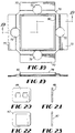
- FIG. 14 is a top plan view of an embodiment of a junction box hatch cover that has a wide lip to make apparent the location of the junction box positioned under the hatch cover. The hatch cover is shown in place on the junction box of the present invention.
- FIG. 15 is a cross-sectional view of the junction box and hatch cover taken along lines 15-15 in FIG. 14 illustrating the cable access apparatus closed and (in phantom lines) in an open position.
- FIG. 16 is a fragmentary top plan view showing an alternative embodiment of the hatch cover shown in FIG. 14 with a different cable access apparatus.
- FIG. 17 is a cross-sectional view taken along lines 17-17 in FIG. 16, showing the cable access apparatus closed and (in phantom lines) in open positions.
- FIG. 18 is a top plan view of an embodiment of the junction box hatch cover of the present invention with an upstanding lip surrounding the junction box access hatch. The hatch cover is shown in place on the junction box of the present invention.
- FIG. 19 is a cross-sectional view taken along lines 19-19 in FIG. 18.
- FIG. 20 is a front elevation view of a typical receptacle frame for use in connection with the junction box of the present invention.
- FIG. 21 is a side elevation view of the frame shown in FIG. 20.
- FIG. 22 is a front elevation view of a second typical receptacle frame for use in the junction box of the present invention.
- FIG. 23 is a side elevation view of the frame shown in FIG. 22.
- the junction box 38 of the present invention generally comprises a housing 40 shown in top plan view in FIG. 4 and a cover 42 shown in Figures 7, 8, and 9.
- Housing 40 has a central area 44 and eight receptacle boxes 46 .
- Receptacle boxes 46 are separated from the central area 44 by slide-in frames such as frame 48 in FIGS. 20 and 21 or frame 50 in FIGS. 22 and 23. Frames are visible in FIGS. 1 through 3.
- the frames, such as frames 48 and 50 are received in tracks 58 on the insides of box walls 56 . Cables enter boxes 46 through cable holes 52 visible in FIG. 5, and cables may be protected by cable feed-throughs shown positioned in cable holes 52 in FIGS. 1 through 3.
- Frames 48 and 50 may be easily attached to the central opening of the frames 48 and 50 . Such attachment can occur by, for instance, providing the outlet with flexible prongs that bend when the outlet is inserted into the opening in order to allow insertion, then flex back to their original position to hold the outlet within the opening.
- numerous frames 48 and 50 with different sized openings may be formed of an inexpensive plastics type material and provided to installers of the housing 40 .
- Frames 48 and 50 with the different sized openings allow easy installation of virtually any type of component, whether electrical outlet, data communication outlet or telephone jack, regardless of whether the same components are produced by different manufacturers.
- Frames 48 and 50 save significantly on installation time, and thus labor cost, since the installer need only snap the chosen outlet into the correct frame, slide each such assembled frame into the notch in the housing, and then place the housing among the pedestals, as shown in FIG. 1.
- Frames may also be used with the housings 40 by providing snap-locking tabs on the outer edges of the frames. The tabs would hold the frames within the openings of the housings 40 .
- the housings 40 could be modified to accept the frames by simply snipping away the portion of the housing 40 located beneath the opening to form a notch that readily accepts a frame. If the frames are formed of a good dielectric material, any electrical components will be isolated from the junction box housing. Such isolation eliminates the need for grounding the housing and allows compliance with various standards, such as European installation standards IP 2,4 and 7.
- junction box 38 comprising housing 40 and cover 42 is positioned on low profile raised flooring standoffs so that a standoff protrudes through standoff opening 54 (visible in FIGS. 2 and 3) and a standoff is positioned adjacent to each side 56 of each box 46 .
- Gussets 60 between adjacent box walls 56 and between box walls 56 and housing walls 62 reinforce and strengthen housing 40 .
- Optional openings 64 at the bottom corners of boxes 46 provide drainage for any moisture that may accumulate in the boxes 46 .
- such openings 64 may be omitted if it is desired that the box 38 be sealed against water entry from below as might occur if a substantial quantity of standing water accumulates on the floor.
- FIGS. 7, 8, and 9 illustrate the junction box cover 42 of the present invention.
- Cover 42 generally has a cruciform shape with a central hatch opening 66 defined by a hatch frame 68 and four box covering plates 70 , each of which covers two boxes 46 and each of which has a laterally centered opening 72 that receives the top of a low profile raised flooring standoff.
- FIGS. 10 through 17 Alternative hatch covers and cable access and cover devices are illustrated in FIGS. 10 through 17.
- the hatch cover 74 illustrated in FIGS. 10-13 presents a carpet support surface generally coplanar with surfaces adjacent to the junction box. It may be fabricated of steel or plastic.
- the hatch cover 76 illustrated in FIGS. 14-17 is typically made of plastic and presents a prominent frame to make apparent the location of the junction box.
- FIGS. 18-19 illustrate an alternative junction box cover 78 that has a relatively tall upstanding lip 80 .
- the principal components of the junction boxes and hatch covers of the present invention are desirably manufactured from polypropylene, although a variety of other thermoplastic and thermoset resin systems and materials may be used in appropriate heat-forming injection molding or other fabrication techniques. Such resin systems may be used with a wide variety of appropriate fillers and reinforcement materials, particularly including fibers reinforcement materials such as fiberglass.
- junction box 38 of the present invention is installed (including the cover 42) together with a hatch cover and other components of a floor system, any water showered onto the box from above (as in IP 2.4.7) is deflected around the box, and little if any such water enters the box.
- IP 2.4.7 IP 2.4.7
Abstract
Description
The foregoing is provided for purposes of explanation and disclosure of preferred embodiments of the present invention. For instance, the shape of the junction box housing or receptacle boxes may be modified, yet still fall within the following claims. Further modifications and adaptations to the described embodiments will be apparent to those skilled in the art and may be made without departing from the scope of the invention, which is defined by the following claims.
Claims (8)
- A junction box (38) for use with a false flooring system having standoffs for supporting floor panels comprising:comprising a central aperture capable of accepting a cable connector means, for insertion into the tracks (58) .(a) a housing (40) defining a plurality of side walls (62) joined to form a closed perimeter and a bottom;(b) at least one receptacle box (46) for enclosing outlets, wherein the receptacle box (46) is attached to at least one side wall; and(c) tracks (58) formed on the inside of the receptacle box (46) and a frame (48 or 50),
- A junction box (38) according to claim 1 further comprising a second receptacle box (46) and means for contacting a selected group of the standoffs in order to position the junction box (38) within the false flooring system.
- A junction box (38) according to claim 2 further comprising a cover (42) for completely enclosing outlets placed within the receptacle boxes (46).
- A junction box (38) according to claim 3 in which the cover (42) forms openings (72) through which the standoffs protrude.
- A junction box (38) according to claim 4 in which the housing (40) forms a generally square perimeter and at least one receptacle box (46) is located on each corner of the square.
- A junction box (38) according to any of claims 1 or 2 in which the housing (40) further comprises a bottom and a cover (42), each of which is shaped to minimize fluid entry into the junction box (38).
- A junction box (38) according to claim 6 further comprising a hatch formed in the cover (42) for allowing access to the interior of the housing (40).
- A junction box (38) according to any of claims 1 through 5, wherein the side walls (62) enclose a central area (44) and the at least one frame (48 or 50) faces the central area (44) and is detachably connected to the receptacle boxes (46) for positioning and holding the outlet.
Applications Claiming Priority (5)
| Application Number | Priority Date | Filing Date | Title |
|---|---|---|---|
| US517895P | 1995-09-29 | 1995-09-29 | |
| US5178P | 1995-09-29 | ||
| US08/715,787 US5828001A (en) | 1995-02-15 | 1996-09-19 | Plastic junction box with receptacle boxes |
| US715787 | 1996-09-19 | ||
| PCT/US1996/015166 WO1997012433A1 (en) | 1995-09-29 | 1996-09-23 | Plastic junction box with receptacle boxes |
Publications (2)
| Publication Number | Publication Date |
|---|---|
| EP0852839A1 EP0852839A1 (en) | 1998-07-15 |
| EP0852839B1 true EP0852839B1 (en) | 2000-03-08 |
Family
ID=26674021
Family Applications (1)
| Application Number | Title | Priority Date | Filing Date |
|---|---|---|---|
| EP96932302A Expired - Lifetime EP0852839B1 (en) | 1995-09-29 | 1996-09-23 | Plastic junction box with receptacle boxes |
Country Status (16)
| Country | Link |
|---|---|
| EP (1) | EP0852839B1 (en) |
| KR (1) | KR19990063722A (en) |
| CN (1) | CN1053299C (en) |
| AT (1) | ATE190440T1 (en) |
| AU (1) | AU704088B2 (en) |
| BR (1) | BR9610668A (en) |
| CA (1) | CA2231859A1 (en) |
| DE (1) | DE69607020T2 (en) |
| EA (1) | EA000289B1 (en) |
| ES (1) | ES2146019T3 (en) |
| GR (1) | GR3033582T3 (en) |
| MX (1) | MX9802456A (en) |
| NO (1) | NO981397D0 (en) |
| NZ (1) | NZ319025A (en) |
| PT (1) | PT852839E (en) |
| WO (1) | WO1997012433A1 (en) |
Families Citing this family (5)
| Publication number | Priority date | Publication date | Assignee | Title |
|---|---|---|---|---|
| DE10310630B3 (en) | 2003-03-10 | 2004-12-16 | Aloys Mennekes Anlagengesellschaft Mbh & Co. Kg | Kit for a plug-in combination |
| DE102005056215B4 (en) * | 2005-11-25 | 2013-05-23 | Rittal Gmbh & Co. Kg | Device for guiding cables or lines |
| KR100831343B1 (en) * | 2007-01-31 | 2008-05-22 | 에이앤피테크놀로지 주식회사 | Electric wire clamp for preventing submersion |
| EP2924831B1 (en) * | 2014-03-27 | 2016-11-02 | Vergokan | Adjustable floor box for floor trunk systems. |
| RU197763U1 (en) * | 2020-02-28 | 2020-05-28 | Игорь Сергеевич Старшинов | DECORATIVE COVER |
Family Cites Families (4)
| Publication number | Priority date | Publication date | Assignee | Title |
|---|---|---|---|---|
| FR2623029B1 (en) * | 1987-11-10 | 1990-03-30 | Lepaillier Patrick | DISTRIBUTION SLAB FOR THE WIRING OF BUILDINGS AND METHOD FOR WIRING A TILE ASSEMBLY |
| US5057647A (en) * | 1988-04-27 | 1991-10-15 | Bogden Emil A | Low rise flooring structure |
| US5052157A (en) * | 1990-02-02 | 1991-10-01 | Servoplan, S.A. | Flooring system especially designed for facilities which house data processing equipment |
| US5362922A (en) * | 1992-09-30 | 1994-11-08 | Thomas & Betts Corporation | Electrical floor box divider |
-
1996
- 1996-09-23 CA CA002231859A patent/CA2231859A1/en not_active Abandoned
- 1996-09-23 EA EA199800346A patent/EA000289B1/en not_active IP Right Cessation
- 1996-09-23 NZ NZ319025A patent/NZ319025A/en unknown
- 1996-09-23 KR KR1019980702189A patent/KR19990063722A/en not_active Application Discontinuation
- 1996-09-23 ES ES96932302T patent/ES2146019T3/en not_active Expired - Lifetime
- 1996-09-23 BR BR9610668-9A patent/BR9610668A/en unknown
- 1996-09-23 WO PCT/US1996/015166 patent/WO1997012433A1/en not_active Application Discontinuation
- 1996-09-23 AT AT96932302T patent/ATE190440T1/en not_active IP Right Cessation
- 1996-09-23 CN CN96197277A patent/CN1053299C/en not_active Expired - Fee Related
- 1996-09-23 PT PT96932302T patent/PT852839E/en unknown
- 1996-09-23 AU AU71156/96A patent/AU704088B2/en not_active Ceased
- 1996-09-23 DE DE69607020T patent/DE69607020T2/en not_active Expired - Fee Related
- 1996-09-23 EP EP96932302A patent/EP0852839B1/en not_active Expired - Lifetime
-
1998
- 1998-03-27 NO NO981397A patent/NO981397D0/en not_active Application Discontinuation
- 1998-03-27 MX MX9802456A patent/MX9802456A/en unknown
-
2000
- 2000-05-31 GR GR20000401277T patent/GR3033582T3/en not_active IP Right Cessation
Also Published As
| Publication number | Publication date |
|---|---|
| BR9610668A (en) | 1999-12-21 |
| NO981397L (en) | 1998-03-27 |
| NZ319025A (en) | 1999-06-29 |
| CA2231859A1 (en) | 1997-04-03 |
| PT852839E (en) | 2000-08-31 |
| MX9802456A (en) | 1998-11-29 |
| AU704088B2 (en) | 1999-04-15 |
| DE69607020D1 (en) | 2000-04-13 |
| NO981397D0 (en) | 1998-03-27 |
| CN1198266A (en) | 1998-11-04 |
| DE69607020T2 (en) | 2001-03-15 |
| ATE190440T1 (en) | 2000-03-15 |
| EA000289B1 (en) | 1999-02-25 |
| EA199800346A1 (en) | 1998-12-24 |
| EP0852839A1 (en) | 1998-07-15 |
| KR19990063722A (en) | 1999-07-26 |
| WO1997012433A1 (en) | 1997-04-03 |
| GR3033582T3 (en) | 2000-09-29 |
| CN1053299C (en) | 2000-06-07 |
| ES2146019T3 (en) | 2000-07-16 |
| AU7115696A (en) | 1997-04-17 |
Similar Documents
| Publication | Publication Date | Title |
|---|---|---|
| US5673522A (en) | Junction box forlow profile raised panel flooring | |
| US6612081B2 (en) | Water-tight cover assembly for an in-floor fitting | |
| US7075005B1 (en) | Electrical floor box with dual cover installation | |
| US20040106313A1 (en) | Electrical termination module | |
| US5828001A (en) | Plastic junction box with receptacle boxes | |
| US5713168A (en) | Junction box for low profile raised panel flooring | |
| US6854226B2 (en) | Cover assembly for an in-floor fitting | |
| US4627684A (en) | Housing for electrical connectors | |
| US6211460B1 (en) | Multi-device yoke for a surface raceway system | |
| US5243129A (en) | Flexible undercarpet power system | |
| EP0852839B1 (en) | Plastic junction box with receptacle boxes | |
| US6710244B1 (en) | Base board system for installing wiring and method therefor | |
| US5019672A (en) | Access floor construction | |
| US4958047A (en) | Monument fitting | |
| GB2453726A (en) | Electrical service outlet box and floor tile assembly | |
| JPH11512917A (en) | Plastic connection box with container box | |
| EP2006966A1 (en) | Electrical and service distribution system | |
| NO964020L (en) | Collection box for raised low profile panel floor | |
| JPH0622434A (en) | Unit board equipped with double floor receptacle and double floor wiring system | |
| CA2151201A1 (en) | Electrical outlets for a suspended flooring system | |
| JPH11164439A (en) | Wiring duct |
Legal Events
| Date | Code | Title | Description |
|---|---|---|---|
| PUAI | Public reference made under article 153(3) epc to a published international application that has entered the european phase |
Free format text: ORIGINAL CODE: 0009012 |
|
| 17P | Request for examination filed |
Effective date: 19980306 |
|
| AK | Designated contracting states |
Kind code of ref document: A1 Designated state(s): AT BE CH DE DK ES FI FR GB GR IE IT LI LU MC NL PT SE |
|
| 17Q | First examination report despatched |
Effective date: 19980720 |
|
| GRAG | Despatch of communication of intention to grant |
Free format text: ORIGINAL CODE: EPIDOS AGRA |
|
| GRAG | Despatch of communication of intention to grant |
Free format text: ORIGINAL CODE: EPIDOS AGRA |
|
| GRAH | Despatch of communication of intention to grant a patent |
Free format text: ORIGINAL CODE: EPIDOS IGRA |
|
| GRAH | Despatch of communication of intention to grant a patent |
Free format text: ORIGINAL CODE: EPIDOS IGRA |
|
| GRAA | (expected) grant |
Free format text: ORIGINAL CODE: 0009210 |
|
| AK | Designated contracting states |
Kind code of ref document: B1 Designated state(s): AT BE CH DE DK ES FI FR GB GR IE IT LI LU MC NL PT SE |
|
| PG25 | Lapsed in a contracting state [announced via postgrant information from national office to epo] |
Ref country code: SE Free format text: THE PATENT HAS BEEN ANNULLED BY A DECISION OF A NATIONAL AUTHORITY Effective date: 20000308 Ref country code: FI Free format text: LAPSE BECAUSE OF FAILURE TO SUBMIT A TRANSLATION OF THE DESCRIPTION OR TO PAY THE FEE WITHIN THE PRESCRIBED TIME-LIMIT Effective date: 20000308 |
|
| REF | Corresponds to: |
Ref document number: 190440 Country of ref document: AT Date of ref document: 20000315 Kind code of ref document: T |
|
| REG | Reference to a national code |
Ref country code: CH Ref legal event code: EP |
|
| REF | Corresponds to: |
Ref document number: 69607020 Country of ref document: DE Date of ref document: 20000413 |
|
| REG | Reference to a national code |
Ref country code: IE Ref legal event code: FG4D |
|
| ITF | It: translation for a ep patent filed |
Owner name: NOTARBARTOLO & GERVASI S.P.A. |
|
| REG | Reference to a national code |
Ref country code: DK Ref legal event code: T3 |
|
| REG | Reference to a national code |
Ref country code: CH Ref legal event code: NV Representative=s name: R. A. EGLI & CO. PATENTANWAELTE |
|
| ET | Fr: translation filed | ||
| REG | Reference to a national code |
Ref country code: ES Ref legal event code: FG2A Ref document number: 2146019 Country of ref document: ES Kind code of ref document: T3 |
|
| REG | Reference to a national code |
Ref country code: PT Ref legal event code: SC4A Free format text: AVAILABILITY OF NATIONAL TRANSLATION Effective date: 20000512 |
|
| PGFP | Annual fee paid to national office [announced via postgrant information from national office to epo] |
Ref country code: MC Payment date: 20000905 Year of fee payment: 5 |
|
| PGFP | Annual fee paid to national office [announced via postgrant information from national office to epo] |
Ref country code: LU Payment date: 20000915 Year of fee payment: 5 |
|
| PGFP | Annual fee paid to national office [announced via postgrant information from national office to epo] |
Ref country code: IE Payment date: 20000929 Year of fee payment: 5 |
|
| PLBE | No opposition filed within time limit |
Free format text: ORIGINAL CODE: 0009261 |
|
| STAA | Information on the status of an ep patent application or granted ep patent |
Free format text: STATUS: NO OPPOSITION FILED WITHIN TIME LIMIT |
|
| 26N | No opposition filed | ||
| PG25 | Lapsed in a contracting state [announced via postgrant information from national office to epo] |
Ref country code: MC Free format text: LAPSE BECAUSE OF NON-PAYMENT OF DUE FEES Effective date: 20010923 Ref country code: LU Free format text: LAPSE BECAUSE OF NON-PAYMENT OF DUE FEES Effective date: 20010923 |
|
| PG25 | Lapsed in a contracting state [announced via postgrant information from national office to epo] |
Ref country code: IE Free format text: LAPSE BECAUSE OF NON-PAYMENT OF DUE FEES Effective date: 20010924 |
|
| REG | Reference to a national code |
Ref country code: GB Ref legal event code: IF02 |
|
| REG | Reference to a national code |
Ref country code: IE Ref legal event code: MM4A |
|
| PGFP | Annual fee paid to national office [announced via postgrant information from national office to epo] |
Ref country code: GB Payment date: 20050914 Year of fee payment: 10 |
|
| PGFP | Annual fee paid to national office [announced via postgrant information from national office to epo] |
Ref country code: NL Payment date: 20050916 Year of fee payment: 10 |
|
| PGFP | Annual fee paid to national office [announced via postgrant information from national office to epo] |
Ref country code: FR Payment date: 20050919 Year of fee payment: 10 |
|
| PGFP | Annual fee paid to national office [announced via postgrant information from national office to epo] |
Ref country code: CH Payment date: 20050921 Year of fee payment: 10 Ref country code: AT Payment date: 20050921 Year of fee payment: 10 |
|
| PGFP | Annual fee paid to national office [announced via postgrant information from national office to epo] |
Ref country code: PT Payment date: 20050922 Year of fee payment: 10 Ref country code: DK Payment date: 20050922 Year of fee payment: 10 |
|
| PGFP | Annual fee paid to national office [announced via postgrant information from national office to epo] |
Ref country code: GR Payment date: 20050927 Year of fee payment: 10 Ref country code: ES Payment date: 20050927 Year of fee payment: 10 |
|
| PGFP | Annual fee paid to national office [announced via postgrant information from national office to epo] |
Ref country code: BE Payment date: 20051017 Year of fee payment: 10 |
|
| PGFP | Annual fee paid to national office [announced via postgrant information from national office to epo] |
Ref country code: DE Payment date: 20051031 Year of fee payment: 10 |
|
| PG25 | Lapsed in a contracting state [announced via postgrant information from national office to epo] |
Ref country code: AT Free format text: LAPSE BECAUSE OF NON-PAYMENT OF DUE FEES Effective date: 20060923 |
|
| PG25 | Lapsed in a contracting state [announced via postgrant information from national office to epo] |
Ref country code: LI Free format text: LAPSE BECAUSE OF NON-PAYMENT OF DUE FEES Effective date: 20060930 Ref country code: CH Free format text: LAPSE BECAUSE OF NON-PAYMENT OF DUE FEES Effective date: 20060930 Ref country code: BE Free format text: LAPSE BECAUSE OF NON-PAYMENT OF DUE FEES Effective date: 20060930 |
|
| PGFP | Annual fee paid to national office [announced via postgrant information from national office to epo] |
Ref country code: IT Payment date: 20060930 Year of fee payment: 11 |
|
| PG25 | Lapsed in a contracting state [announced via postgrant information from national office to epo] |
Ref country code: DK Free format text: LAPSE BECAUSE OF NON-PAYMENT OF DUE FEES Effective date: 20061002 |
|
| PG25 | Lapsed in a contracting state [announced via postgrant information from national office to epo] |
Ref country code: PT Free format text: LAPSE BECAUSE OF NON-PAYMENT OF DUE FEES Effective date: 20070323 |
|
| PG25 | Lapsed in a contracting state [announced via postgrant information from national office to epo] |
Ref country code: NL Free format text: LAPSE BECAUSE OF NON-PAYMENT OF DUE FEES Effective date: 20070401 |
|
| PG25 | Lapsed in a contracting state [announced via postgrant information from national office to epo] |
Ref country code: DE Free format text: LAPSE BECAUSE OF NON-PAYMENT OF DUE FEES Effective date: 20070403 |
|
| REG | Reference to a national code |
Ref country code: PT Ref legal event code: MM4A Free format text: LAPSE DUE TO NON-PAYMENT OF FEES Effective date: 20070323 Ref country code: DK Ref legal event code: EBP |
|
| REG | Reference to a national code |
Ref country code: CH Ref legal event code: PL |
|
| GBPC | Gb: european patent ceased through non-payment of renewal fee |
Effective date: 20060923 |
|
| NLV4 | Nl: lapsed or anulled due to non-payment of the annual fee |
Effective date: 20070401 |
|
| REG | Reference to a national code |
Ref country code: FR Ref legal event code: ST Effective date: 20070531 |
|
| PG25 | Lapsed in a contracting state [announced via postgrant information from national office to epo] |
Ref country code: GB Free format text: LAPSE BECAUSE OF NON-PAYMENT OF DUE FEES Effective date: 20060923 |
|
| REG | Reference to a national code |
Ref country code: ES Ref legal event code: FD2A Effective date: 20060925 |
|
| BERE | Be: lapsed |
Owner name: *GUILFORD (DELAWARE) INC. Effective date: 20060930 |
|
| PG25 | Lapsed in a contracting state [announced via postgrant information from national office to epo] |
Ref country code: ES Free format text: LAPSE BECAUSE OF NON-PAYMENT OF DUE FEES Effective date: 20060925 |
|
| PG25 | Lapsed in a contracting state [announced via postgrant information from national office to epo] |
Ref country code: FR Free format text: LAPSE BECAUSE OF NON-PAYMENT OF DUE FEES Effective date: 20061002 |
|
| PG25 | Lapsed in a contracting state [announced via postgrant information from national office to epo] |
Ref country code: GR Free format text: LAPSE BECAUSE OF NON-PAYMENT OF DUE FEES Effective date: 20070404 |
|
| PG25 | Lapsed in a contracting state [announced via postgrant information from national office to epo] |
Ref country code: IT Free format text: LAPSE BECAUSE OF NON-PAYMENT OF DUE FEES Effective date: 20070923 |