EP0852166B1 - Tauchgiessrohr für Giessformen in Stranggiessanlagen - Google Patents
Tauchgiessrohr für Giessformen in Stranggiessanlagen Download PDFInfo
- Publication number
- EP0852166B1 EP0852166B1 EP97830676A EP97830676A EP0852166B1 EP 0852166 B1 EP0852166 B1 EP 0852166B1 EP 97830676 A EP97830676 A EP 97830676A EP 97830676 A EP97830676 A EP 97830676A EP 0852166 B1 EP0852166 B1 EP 0852166B1
- Authority
- EP
- European Patent Office
- Prior art keywords
- discharge nozzle
- outlets
- main body
- outflow duct
- moulds
- Prior art date
- Legal status (The legal status is an assumption and is not a legal conclusion. Google has not performed a legal analysis and makes no representation as to the accuracy of the status listed.)
- Expired - Lifetime
Links
Images
Classifications
-
- B—PERFORMING OPERATIONS; TRANSPORTING
- B22—CASTING; POWDER METALLURGY
- B22D—CASTING OF METALS; CASTING OF OTHER SUBSTANCES BY THE SAME PROCESSES OR DEVICES
- B22D41/00—Casting melt-holding vessels, e.g. ladles, tundishes, cups or the like
- B22D41/50—Pouring-nozzles
Definitions
- the present invention relates to a discharge nozzle for moulds in continuous casting machines and, more specifically, to a discharge nozzle of molten metal having directed outlets for moulds in continuous casting machines.
- One known method is that of using a device external to the mould , known as an electromagnetic brake which, by means of an electromagnetic field induced in the bath, influences the movement of the metal, thus reducing stirring in the bath.
- the disadvantage of a device of this kind is that it involves extremely high costs and, like all external devices in a system, the additional need for maintenance and control.
- a discharge nozzle with four outlets arranged in the same plane and wherein the upper outlets have a smaller size and are downwards oriented, and the lower outlets have a bigger size and are upwards oriented, in order to reduce turbulence to the bath of molten metal while decreasing the energy of the jet.
- the object of the present invention is to solve the above mentioned problems by providing a discharge nozzle having its outlets arranged in such a way as to induce a damping effect on the energy of the jet of metal passing through said outlets, and such that said damping effect increases proportionally to the increase of flow rate, thus decreasing stirring in the bath of the mould.
- a further object of the present invention is to provide a discharge nozzle for moulds that is of simple construction, provides a high level of reliability and in which only normal maintenance operations are required.
- a discharge nozzle for moulds in continuous casting machines comprises:
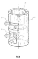
- the discharge nozzle has a body 1 with a substantially cylindrical shape, within which an outflow duct 2 for the molten metal is formed.
- said duct 2 has a steady cross-section until a predetermined length, at which point two outlets 3 are formed (only one of them is shown in the figure). From that length onwards, the section of the duct 2 decreases and extends for a further determined distance, at which point, in a similar manner to that above, two outlets 4 are formed (only one of them is shown in the figure), which are larger than the two openings 3.
- the openings 3 and 4 are arranged in an horizontal direction, that is to say at right angles to the longitudinal direction of the discharge nozzle.
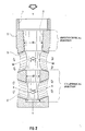
- the discharge nozzle has a body 5 with a substantially cylindrical section, inside which an outflow duct 6 is formed.
- the duct 6 has a thread 7 for the engaging with the feeder duct of the discharge nozzle (not shown in the figure) in a known manner.
- the duct 6 is frustoconical along its length, that is to say it has a cross-section that decreases as said duct advances.
- outlets 8 are formed, both of same size and arranged in a diametrically opposite position. Said outlets 8 are directed upwards so that their longitudinal axis X forms an angle ⁇ with the longitudinal axis Y of the discharge nozzle.
- outlets 8 are formed, both of same size but larger than the openings 8 and arranged in a diametrically opposite position. Said outlets 9 are directed downwards and in such a way that their longitudinal axis W forms an angle ⁇ with the longitudinal axis Y of the discharge nozzle.
- both upper outlets 9 and bottom openings 8 is such to give to both the flows of metal passing through them a direction that tends to gather the two flows, i.e. in such a way that the upper flow meets the bottom flow, providing a damping effect on the kinetic energy of both flows, said damping effect increasing as the flow rate increases, and therefore during high production function.
- Table 1 illustrates the parameters for optimum sizing of the discharge nozzle, in a non-dimensional form and with reference to figure 2, according to the present invention.
- Table 2 illustrates performance parameters, expressed as normalised values, resulting from comparison of the discharge nozzle according to the present invention and a standard two-outlets discharge nozzle.
- DISCHARGE NOZZLE DIMENSIONS NON-DIMENSIONAL PARAMETERS Top diameter of duct D Bottom diameter of duct (D') 0.7 ⁇ 0.8 D Top external diameter of discharge nozzle 1.71 D Bottom external diameter of discharge nozzle 1.57 D Position of bottom outlets starting from lower end of discharge nozzle 1.03 D Position of upper outlets starting from lower end of discharge nozzle 2.32 D Angle ⁇ between X axis of bottom outlets and longitudinal axis Y of discharge nozzle 60° ⁇ ⁇ ⁇ 90° Angle ⁇ between W axis of upper outlets and longitudinal axis Y of discharge nozzle 60° ⁇ ⁇ ⁇ 90° Diameter of upper outlets 0.92 D Diameter of bottom outlets 0.85 D PARAMETERS Standard discharge nozzle Discharge nozzle according to the invention Impact speed (m/s) 0.22 0.13 Impact point (mm) 320 250 Wave index
- the impact speed on the side walls of the mould decreased by approximately 40%, the wave level by 10% and the formation of vortexes by 50%. Only the index of lack of thermal uniformity is slightly worse, but on the basis of the experience of any technician skilled in the art the overall values give a strong indication of improvement.
- the present invention is not limited to the embodiment described above, but comprises any alternative version thereof.
Landscapes
- Engineering & Computer Science (AREA)
- Mechanical Engineering (AREA)
- Continuous Casting (AREA)
- Ship Loading And Unloading (AREA)
- Casting Support Devices, Ladles, And Melt Control Thereby (AREA)
- Moulds For Moulding Plastics Or The Like (AREA)
- Fertilizing (AREA)
- Nozzles (AREA)
Claims (6)
- Strahldüse für Formen in Stranggussmaschinen, die umfasst:dadurch gekennzeichnet, dass jeder Auslass der wenigstens zwei ersten Auslasse (8) eine Aufwärtsrichtung und ein Durchmesserverhältnis von 0,85 D hat, und dass jeder Auslass der wenigstens zwei zweiten Auslasse (9) eine Abwärtsrichtung und ein Durchmesserverhältnis von 0,92 D hat.einen Hauptkörper (5) mit zylindrischer Form;eine Austrittsleitung (6), die im Inneren des Hauptkörpers (5) ausgebildet ist und einen vorgegebenen Durchmesser (D) hat;wenigstens zwei erste Auslasse (8), die symmetrisch zueinander am Außenumfang des Hauptkörpers (5) und am unteren Ende des Hauptkörpers (5) angeordnet sind, um Verbindung der Austrittsleitung (6) nach außen herzustellen;wenigstens zwei zweite Auslasse (9), die symmetrisch zueinander am Außenumfang des Hauptkörpers (5) und über den wenigstens zwei ersten Öffnungen (8) angeordnet sind, um Verbindung der Austrittsleitung (6) nach außen herzustellen;
- Strahldüse für Formen in Stranggussmaschinen nach Anspruch 1, wobei die Austrittsleitung (6) nach unten kegelstumpfförmig ist.
- Strahldüse nach Anspruch 1 oder 2, wobei die geometrische Achse (X) jedes Auslasses der wenigstens zwei ersten Auslasse (8) nach oben gerichtet ist und einen Winkel (α), der zwischen 60° und weniger als 90° liegt, zur Längsachse (Y) der Austrittsleitung (6) bildet.
- Austrittsdüse nach Anspruch 1 oder 2 oder 3, wobei die geometrische Achse (W) jedes Auslasses der wenigstens zwei zweiten Auslasse (9) nach unten gerichtet ist und einen Winkel (β), der zwischen 60° und weniger als 90° liegt, zur Längsachse (Y) der Austrittsleitung (6) bildet.
- Strahldüse nach Anspruch 3, wobei der Winkel (α) 75° beträgt.
- Strahldüse nach Anspruch 4, wobei der Winkel (β) 75° beträgt.
Applications Claiming Priority (2)
| Application Number | Priority Date | Filing Date | Title |
|---|---|---|---|
| ITRM960869 | 1996-12-16 | ||
| IT96RM000869A IT1289251B1 (it) | 1996-12-16 | 1996-12-16 | Scaricatore per lingotteria in macchine di colata continua |
Publications (3)
| Publication Number | Publication Date |
|---|---|
| EP0852166A2 EP0852166A2 (de) | 1998-07-08 |
| EP0852166A3 EP0852166A3 (de) | 1998-07-22 |
| EP0852166B1 true EP0852166B1 (de) | 2002-07-24 |
Family
ID=11404595
Family Applications (1)
| Application Number | Title | Priority Date | Filing Date |
|---|---|---|---|
| EP97830676A Expired - Lifetime EP0852166B1 (de) | 1996-12-16 | 1997-12-16 | Tauchgiessrohr für Giessformen in Stranggiessanlagen |
Country Status (5)
| Country | Link |
|---|---|
| EP (1) | EP0852166B1 (de) |
| AT (1) | ATE220963T1 (de) |
| DE (1) | DE69714203T2 (de) |
| ES (1) | ES2183119T3 (de) |
| IT (1) | IT1289251B1 (de) |
Cited By (1)
| Publication number | Priority date | Publication date | Assignee | Title |
|---|---|---|---|---|
| AU2004291536B2 (en) * | 2003-11-17 | 2009-05-07 | Vesuvius Crucible Company | Multi-outlet casting nozzle |
Families Citing this family (1)
| Publication number | Priority date | Publication date | Assignee | Title |
|---|---|---|---|---|
| DE10113026C2 (de) * | 2001-03-17 | 2003-03-27 | Thyssenkrupp Stahl Ag | Tauchrohr für das Vergießen von Metallschmelze, insbesondere von Stahlschmelze |
Family Cites Families (5)
| Publication number | Priority date | Publication date | Assignee | Title |
|---|---|---|---|---|
| DE1287752B (de) * | 1966-08-03 | 1969-01-23 | Mannesmann Ag | Verteilerausguss in Stranggiessanlagen |
| US3371704A (en) * | 1967-02-20 | 1968-03-05 | Astrov Evgeny Ivanovitch | Device for supplying molten metal into a mould of a continuous casting machine |
| JPS61180656A (ja) * | 1985-02-07 | 1986-08-13 | Nippon Kokan Kk <Nkk> | 連続鋳造用浸漬ノズル |
| JPS61226149A (ja) * | 1985-04-01 | 1986-10-08 | Nippon Kokan Kk <Nkk> | 連続鋳造用浸漬ノズル |
| GB8814331D0 (en) * | 1988-06-16 | 1988-07-20 | Davy Distington Ltd | Continuous casting of steel |
-
1996
- 1996-12-16 IT IT96RM000869A patent/IT1289251B1/it active IP Right Grant
-
1997
- 1997-12-16 DE DE69714203T patent/DE69714203T2/de not_active Expired - Fee Related
- 1997-12-16 EP EP97830676A patent/EP0852166B1/de not_active Expired - Lifetime
- 1997-12-16 ES ES97830676T patent/ES2183119T3/es not_active Expired - Lifetime
- 1997-12-16 AT AT97830676T patent/ATE220963T1/de not_active IP Right Cessation
Cited By (1)
| Publication number | Priority date | Publication date | Assignee | Title |
|---|---|---|---|---|
| AU2004291536B2 (en) * | 2003-11-17 | 2009-05-07 | Vesuvius Crucible Company | Multi-outlet casting nozzle |
Also Published As
| Publication number | Publication date |
|---|---|
| EP0852166A2 (de) | 1998-07-08 |
| DE69714203D1 (de) | 2002-08-29 |
| ATE220963T1 (de) | 2002-08-15 |
| EP0852166A3 (de) | 1998-07-22 |
| ITRM960869A1 (it) | 1998-06-16 |
| DE69714203T2 (de) | 2003-03-27 |
| IT1289251B1 (it) | 1998-09-29 |
| ITRM960869A0 (it) | 1996-12-16 |
| ES2183119T3 (es) | 2003-03-16 |
Similar Documents
| Publication | Publication Date | Title |
|---|---|---|
| JP3662973B2 (ja) | 連続鋳造用排出ノズル | |
| RU2165825C2 (ru) | Разливочный стакан для введения жидкого металла в кристаллизатор установки непрерывного литья | |
| US7757747B2 (en) | Submerged entry nozzle | |
| US5882577A (en) | Tundish | |
| EP2279816B1 (de) | Tauchdüse für stranggussvorgänge | |
| US3648761A (en) | Apparatus for distributing molten steel in a mold for a continuous casting | |
| KR20000013111A (ko) | 연속주조방법 및 이에 이용되는 연속주조장치 | |
| WO2011121802A1 (ja) | 浸漬ノズル | |
| JPS63500786A (ja) | 薄い金属鋳片の連続鋳造法と装置 | |
| CA2018079C (en) | Pouring tube for feeding molten steel into a continuous casting mold | |
| KR100355725B1 (ko) | 연속 주조 기계의 주형용 용융 금속 공급기 | |
| US5603860A (en) | Immersed casting tube | |
| EP0852166A2 (de) | Tauchgiessrohr für Giessformen in Stranggiessanlagen | |
| CA2588521C (en) | Continuous steel casting installation for billet and bloom formats | |
| CA2159256A1 (en) | Discharge nozzle for a crystalliser for continuous casting of slabs | |
| US5205343A (en) | Pouring tube for feeding molten steel into a continuous casting mold | |
| CN211758438U (zh) | 一种小方坯高速连铸用浸入式水口 | |
| AU620179B2 (en) | Direct chill casting mould with controllable impringement | |
| UA86601C2 (uk) | Заглибний розливальний стакан з багатьма випускними отворами (варіанти) | |
| EP1854571B1 (de) | Tauchgiessrohr zum Stranggiessen von Stahl | |
| EP1657009A1 (de) | Eintauchdüse zum Stranggießen von Stahl | |
| US6857465B2 (en) | Method for the production of a continously-cast precursor | |
| EP1261446A1 (de) | Verbessertes tauchrohr für das stranggiessen | |
| US4530394A (en) | Controlled water application for electromagnetic casting shape control | |
| US12544828B2 (en) | Method of molten metal casting utilizing an impact pad in the tundish |
Legal Events
| Date | Code | Title | Description |
|---|---|---|---|
| PUAI | Public reference made under article 153(3) epc to a published international application that has entered the european phase |
Free format text: ORIGINAL CODE: 0009012 |
|
| PUAL | Search report despatched |
Free format text: ORIGINAL CODE: 0009013 |
|
| AK | Designated contracting states |
Kind code of ref document: A2 Designated state(s): AT BE DE ES FR GB NL SE |
|
| AX | Request for extension of the european patent |
Free format text: AL;LT;LV;MK;RO;SI |
|
| AK | Designated contracting states |
Kind code of ref document: A3 Designated state(s): AT BE CH DE DK ES FI FR GB GR IE IT LI LU MC NL PT SE |
|
| AX | Request for extension of the european patent |
Free format text: AL;LT;LV;MK;RO;SI |
|
| 17P | Request for examination filed |
Effective date: 19990120 |
|
| AKX | Designation fees paid |
Free format text: AT BE DE ES FR GB NL SE |
|
| RBV | Designated contracting states (corrected) |
Designated state(s): AT BE DE ES FR GB NL SE |
|
| 17Q | First examination report despatched |
Effective date: 19990316 |
|
| GRAG | Despatch of communication of intention to grant |
Free format text: ORIGINAL CODE: EPIDOS AGRA |
|
| GRAG | Despatch of communication of intention to grant |
Free format text: ORIGINAL CODE: EPIDOS AGRA |
|
| GRAH | Despatch of communication of intention to grant a patent |
Free format text: ORIGINAL CODE: EPIDOS IGRA |
|
| GRAH | Despatch of communication of intention to grant a patent |
Free format text: ORIGINAL CODE: EPIDOS IGRA |
|
| GRAA | (expected) grant |
Free format text: ORIGINAL CODE: 0009210 |
|
| AK | Designated contracting states |
Kind code of ref document: B1 Designated state(s): AT BE DE ES FR GB NL SE |
|
| PG25 | Lapsed in a contracting state [announced via postgrant information from national office to epo] |
Ref country code: NL Free format text: LAPSE BECAUSE OF FAILURE TO SUBMIT A TRANSLATION OF THE DESCRIPTION OR TO PAY THE FEE WITHIN THE PRESCRIBED TIME-LIMIT Effective date: 20020724 Ref country code: BE Free format text: LAPSE BECAUSE OF FAILURE TO SUBMIT A TRANSLATION OF THE DESCRIPTION OR TO PAY THE FEE WITHIN THE PRESCRIBED TIME-LIMIT Effective date: 20020724 Ref country code: AT Free format text: LAPSE BECAUSE OF FAILURE TO SUBMIT A TRANSLATION OF THE DESCRIPTION OR TO PAY THE FEE WITHIN THE PRESCRIBED TIME-LIMIT Effective date: 20020724 |
|
| REF | Corresponds to: |
Ref document number: 220963 Country of ref document: AT Date of ref document: 20020815 Kind code of ref document: T |
|
| REG | Reference to a national code |
Ref country code: GB Ref legal event code: FG4D |
|
| REF | Corresponds to: |
Ref document number: 69714203 Country of ref document: DE Date of ref document: 20020829 |
|
| PG25 | Lapsed in a contracting state [announced via postgrant information from national office to epo] |
Ref country code: SE Free format text: LAPSE BECAUSE OF FAILURE TO SUBMIT A TRANSLATION OF THE DESCRIPTION OR TO PAY THE FEE WITHIN THE PRESCRIBED TIME-LIMIT Effective date: 20021024 |
|
| NLV1 | Nl: lapsed or annulled due to failure to fulfill the requirements of art. 29p and 29m of the patents act | ||
| ET | Fr: translation filed | ||
| REG | Reference to a national code |
Ref country code: ES Ref legal event code: FG2A Ref document number: 2183119 Country of ref document: ES Kind code of ref document: T3 |
|
| PLBE | No opposition filed within time limit |
Free format text: ORIGINAL CODE: 0009261 |
|
| STAA | Information on the status of an ep patent application or granted ep patent |
Free format text: STATUS: NO OPPOSITION FILED WITHIN TIME LIMIT |
|
| 26N | No opposition filed |
Effective date: 20030425 |
|
| PGFP | Annual fee paid to national office [announced via postgrant information from national office to epo] |
Ref country code: GB Payment date: 20031217 Year of fee payment: 7 |
|
| PGFP | Annual fee paid to national office [announced via postgrant information from national office to epo] |
Ref country code: FR Payment date: 20031229 Year of fee payment: 7 |
|
| PGFP | Annual fee paid to national office [announced via postgrant information from national office to epo] |
Ref country code: ES Payment date: 20031230 Year of fee payment: 7 |
|
| PGFP | Annual fee paid to national office [announced via postgrant information from national office to epo] |
Ref country code: DE Payment date: 20040130 Year of fee payment: 7 |
|
| PG25 | Lapsed in a contracting state [announced via postgrant information from national office to epo] |
Ref country code: GB Free format text: LAPSE BECAUSE OF NON-PAYMENT OF DUE FEES Effective date: 20041216 |
|
| PG25 | Lapsed in a contracting state [announced via postgrant information from national office to epo] |
Ref country code: ES Free format text: LAPSE BECAUSE OF NON-PAYMENT OF DUE FEES Effective date: 20041217 |
|
| PG25 | Lapsed in a contracting state [announced via postgrant information from national office to epo] |
Ref country code: DE Free format text: LAPSE BECAUSE OF NON-PAYMENT OF DUE FEES Effective date: 20050701 |
|
| GBPC | Gb: european patent ceased through non-payment of renewal fee |
Effective date: 20041216 |
|
| PG25 | Lapsed in a contracting state [announced via postgrant information from national office to epo] |
Ref country code: FR Free format text: LAPSE BECAUSE OF NON-PAYMENT OF DUE FEES Effective date: 20050831 |
|
| REG | Reference to a national code |
Ref country code: FR Ref legal event code: ST |
|
| REG | Reference to a national code |
Ref country code: ES Ref legal event code: FD2A Effective date: 20041217 |