EP0852166B1 - Discharge nozzle for moulds of continuous casting machines - Google Patents
Discharge nozzle for moulds of continuous casting machines Download PDFInfo
- Publication number
- EP0852166B1 EP0852166B1 EP97830676A EP97830676A EP0852166B1 EP 0852166 B1 EP0852166 B1 EP 0852166B1 EP 97830676 A EP97830676 A EP 97830676A EP 97830676 A EP97830676 A EP 97830676A EP 0852166 B1 EP0852166 B1 EP 0852166B1
- Authority
- EP
- European Patent Office
- Prior art keywords
- discharge nozzle
- outlets
- main body
- outflow duct
- moulds
- Prior art date
- Legal status (The legal status is an assumption and is not a legal conclusion. Google has not performed a legal analysis and makes no representation as to the accuracy of the status listed.)
- Expired - Lifetime
Links
Images
Classifications
-
- B—PERFORMING OPERATIONS; TRANSPORTING
- B22—CASTING; POWDER METALLURGY
- B22D—CASTING OF METALS; CASTING OF OTHER SUBSTANCES BY THE SAME PROCESSES OR DEVICES
- B22D41/00—Casting melt-holding vessels, e.g. ladles, tundishes, cups or the like
- B22D41/50—Pouring-nozzles
Definitions
- the present invention relates to a discharge nozzle for moulds in continuous casting machines and, more specifically, to a discharge nozzle of molten metal having directed outlets for moulds in continuous casting machines.
- One known method is that of using a device external to the mould , known as an electromagnetic brake which, by means of an electromagnetic field induced in the bath, influences the movement of the metal, thus reducing stirring in the bath.
- the disadvantage of a device of this kind is that it involves extremely high costs and, like all external devices in a system, the additional need for maintenance and control.
- a discharge nozzle with four outlets arranged in the same plane and wherein the upper outlets have a smaller size and are downwards oriented, and the lower outlets have a bigger size and are upwards oriented, in order to reduce turbulence to the bath of molten metal while decreasing the energy of the jet.
- the object of the present invention is to solve the above mentioned problems by providing a discharge nozzle having its outlets arranged in such a way as to induce a damping effect on the energy of the jet of metal passing through said outlets, and such that said damping effect increases proportionally to the increase of flow rate, thus decreasing stirring in the bath of the mould.
- a further object of the present invention is to provide a discharge nozzle for moulds that is of simple construction, provides a high level of reliability and in which only normal maintenance operations are required.
- a discharge nozzle for moulds in continuous casting machines comprises:
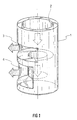
- the discharge nozzle has a body 1 with a substantially cylindrical shape, within which an outflow duct 2 for the molten metal is formed.
- said duct 2 has a steady cross-section until a predetermined length, at which point two outlets 3 are formed (only one of them is shown in the figure). From that length onwards, the section of the duct 2 decreases and extends for a further determined distance, at which point, in a similar manner to that above, two outlets 4 are formed (only one of them is shown in the figure), which are larger than the two openings 3.
- the openings 3 and 4 are arranged in an horizontal direction, that is to say at right angles to the longitudinal direction of the discharge nozzle.
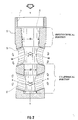
- the discharge nozzle has a body 5 with a substantially cylindrical section, inside which an outflow duct 6 is formed.
- the duct 6 has a thread 7 for the engaging with the feeder duct of the discharge nozzle (not shown in the figure) in a known manner.
- the duct 6 is frustoconical along its length, that is to say it has a cross-section that decreases as said duct advances.
- outlets 8 are formed, both of same size and arranged in a diametrically opposite position. Said outlets 8 are directed upwards so that their longitudinal axis X forms an angle ⁇ with the longitudinal axis Y of the discharge nozzle.
- outlets 8 are formed, both of same size but larger than the openings 8 and arranged in a diametrically opposite position. Said outlets 9 are directed downwards and in such a way that their longitudinal axis W forms an angle ⁇ with the longitudinal axis Y of the discharge nozzle.
- both upper outlets 9 and bottom openings 8 is such to give to both the flows of metal passing through them a direction that tends to gather the two flows, i.e. in such a way that the upper flow meets the bottom flow, providing a damping effect on the kinetic energy of both flows, said damping effect increasing as the flow rate increases, and therefore during high production function.
- Table 1 illustrates the parameters for optimum sizing of the discharge nozzle, in a non-dimensional form and with reference to figure 2, according to the present invention.
- Table 2 illustrates performance parameters, expressed as normalised values, resulting from comparison of the discharge nozzle according to the present invention and a standard two-outlets discharge nozzle.
- DISCHARGE NOZZLE DIMENSIONS NON-DIMENSIONAL PARAMETERS Top diameter of duct D Bottom diameter of duct (D') 0.7 ⁇ 0.8 D Top external diameter of discharge nozzle 1.71 D Bottom external diameter of discharge nozzle 1.57 D Position of bottom outlets starting from lower end of discharge nozzle 1.03 D Position of upper outlets starting from lower end of discharge nozzle 2.32 D Angle ⁇ between X axis of bottom outlets and longitudinal axis Y of discharge nozzle 60° ⁇ ⁇ ⁇ 90° Angle ⁇ between W axis of upper outlets and longitudinal axis Y of discharge nozzle 60° ⁇ ⁇ ⁇ 90° Diameter of upper outlets 0.92 D Diameter of bottom outlets 0.85 D PARAMETERS Standard discharge nozzle Discharge nozzle according to the invention Impact speed (m/s) 0.22 0.13 Impact point (mm) 320 250 Wave index
- the impact speed on the side walls of the mould decreased by approximately 40%, the wave level by 10% and the formation of vortexes by 50%. Only the index of lack of thermal uniformity is slightly worse, but on the basis of the experience of any technician skilled in the art the overall values give a strong indication of improvement.
- the present invention is not limited to the embodiment described above, but comprises any alternative version thereof.
Landscapes
- Engineering & Computer Science (AREA)
- Mechanical Engineering (AREA)
- Continuous Casting (AREA)
- Ship Loading And Unloading (AREA)
- Casting Support Devices, Ladles, And Melt Control Thereby (AREA)
- Moulds For Moulding Plastics Or The Like (AREA)
- Fertilizing (AREA)
- Nozzles (AREA)
Abstract
Description
- The present invention relates to a discharge nozzle for moulds in continuous casting machines and, more specifically, to a discharge nozzle of molten metal having directed outlets for moulds in continuous casting machines.
- The application of discharge nozzles to transfer the liquid metal from a separator, commonly known as a tundish, to the respective mould is known. During transfer of the molten metal, the speed at which the mould is fed has a considerable influence on the quality of the finished product. In fact, one problem that is found is that of a non-homogeneous distribution of the metal in terms of speed and/or temperature. This problem can result in the surface of the bath being too cold or moving too much. In this case, solidification is irregular and the dust covering normally found on the surface of the bath itself can be incorporated into the bath.
- Another problem is found if the streams of molten metal from the discharge nozzle hit the side walls of the mould with excessive energy, resulting in re-founding of the top skin which, if excessive, can compromise process regularity.
- Given the high productivity levels normally required from continuous casting machines, the above problems are very strongly felt when dealing with large flow rates, because any irregularity in the heat exchange and in the possibility to capture surface powders can detract from the quality of both the surface and the inside of the product.
- To solve the above mentioned problems a number of methods have been used. One known method is that of using a device external to the mould , known as an electromagnetic brake which, by means of an electromagnetic field induced in the bath, influences the movement of the metal, thus reducing stirring in the bath. The disadvantage of a device of this kind is that it involves extremely high costs and, like all external devices in a system, the additional need for maintenance and control.
- Another method to solve the above mentioned problems is that of particular care when designing the geometry of the discharge nozzle. From this point of view, the most common practice is that of creating discharge nozzles with outlets that point downwards.
- Furthermore, is known another embodiment in which the discharge nozzle has four horizontal holes instead of two, so as to decrease the energy of the jet of metal.
- For example, is known from DE 1287752 B a discharge nozzle with four outlets arranged in the same plane and wherein the upper outlets have a smaller size and are downwards oriented, and the lower outlets have a bigger size and are upwards oriented, in order to reduce turbulence to the bath of molten metal while decreasing the energy of the jet.
- However, the above solutions only partially solve the problems indicated above, because their object is the effect of the phenomenon, that is to say, for example, excessive surface movement, rather than the cause thereof, which is the excessive energy of the metal to be dealt with. Furthermore, improvements are obtained with reduced flow rates, but not with higher flow rates and so at increased machine productivity.
- Therefore, the object of the present invention is to solve the above mentioned problems by providing a discharge nozzle having its outlets arranged in such a way as to induce a damping effect on the energy of the jet of metal passing through said outlets, and such that said damping effect increases proportionally to the increase of flow rate, thus decreasing stirring in the bath of the mould.
- A further object of the present invention is to provide a discharge nozzle for moulds that is of simple construction, provides a high level of reliability and in which only normal maintenance operations are required.
- According to the present invention, a discharge nozzle for moulds in continuous casting machines comprises:
- a main body of cylindrical shape;
- an outflow duct formed inside said main body and having a set diameter;
- at least two first outlets arranged in a symmetrical manner along the external perimeter of said main body one respect to the other, and at the lower end of said main body in order to communicate said outflow duct towards the outside;
- at least two second outlets arranged in a symmetrical manner along the external perimeter of said main body one respect to the other, and above said at least two first openings, in order to communicate said outflow duct towards the outside; characterised in that each outlet of said at least two first outlets has an upward direction and a diameter ratio of 0.85 times the diameter of the outflow duct, and in that each outlet of said at least two second outlets has a downward direction and a diameter ratio of 0.95 times the diameter of the outflow duct.
-
- The present invention will be illustrated in greater detail in the following by a description of an embodiment thereof, given as a non-limiting example and with reference to the enclosed drawings, in which:
- figure 1 is a schematically perspective view of a discharge nozzle of the prior art; and
- figure 2 is a longitudinal cross section view of a discharge nozzle according to the present invention.
-
- With reference to figure 1, a discharge nozzle according to the prior art is shown.
- The discharge nozzle has a
body 1 with a substantially cylindrical shape, within which anoutflow duct 2 for the molten metal is formed. Initially, saidduct 2 has a steady cross-section until a predetermined length, at which point two outlets 3 are formed (only one of them is shown in the figure). From that length onwards, the section of theduct 2 decreases and extends for a further determined distance, at which point, in a similar manner to that above, twooutlets 4 are formed (only one of them is shown in the figure), which are larger than the two openings 3. - The
openings 3 and 4 are arranged in an horizontal direction, that is to say at right angles to the longitudinal direction of the discharge nozzle. - With reference now to figure 2, a longitudinal cross section view of the discharge nozzle according to the present invention is shown.
- The discharge nozzle has a body 5 with a substantially cylindrical section, inside which an
outflow duct 6 is formed. - In this embodiment, at the top end of said body 5, the
duct 6 has athread 7 for the engaging with the feeder duct of the discharge nozzle (not shown in the figure) in a known manner. - It should be noted that the
duct 6 is frustoconical along its length, that is to say it has a cross-section that decreases as said duct advances. - At approximately one third of the total length of the
duct 6 and starting from the lower end of the body 5, two outlets 8 are formed, both of same size and arranged in a diametrically opposite position. Said outlets 8 are directed upwards so that their longitudinal axis X forms an angle α with the longitudinal axis Y of the discharge nozzle. - Above said outlets 8 and at approximately two thirds of the total length of the duct starting from the lower end of the body 5, two outlets 9 are formed, both of same size but larger than the openings 8 and arranged in a diametrically opposite position. Said outlets 9 are directed downwards and in such a way that their longitudinal axis W forms an angle β with the longitudinal axis Y of the discharge nozzle.
- The arrangement of both upper outlets 9 and bottom openings 8 is such to give to both the flows of metal passing through them a direction that tends to gather the two flows, i.e. in such a way that the upper flow meets the bottom flow, providing a damping effect on the kinetic energy of both flows, said damping effect increasing as the flow rate increases, and therefore during high production function.
- For optimum sizing of the cross-sections, that is to say of the outlets and the duct, calculations have been made using numeric simulation with a commercial calculation code (more specifically the PHOENICS code). Then, once optimum sizing was obtained, a 1:1 scale model was prepared, made of Plexiglas and tested in a mould using water as working fluid.
- When selecting the dimensions, the dissipation of energy in the top surface and at the side walls of the moulds has been taken into account, as well as the temperature of both.
- Subsequently, the performance of the discharge nozzle was compared with a standard two-outlets discharge nozzle. The performance concerned to:
- 1) the impact speed and depth of the jet on the side walls of the mould;
- 2) the tendency to generate a wavy and/or turbulent surface;
- 3) the level of thermal homogeneity on the surface; and
- 4) the index of a good metal flow through the upper portion of the mould.
-
- Herebelow two tables representing the optimum dimensions for a model of a discharge nozzle according to calculations and the experimental results thereof, are given.
- Table 1 illustrates the parameters for optimum sizing of the discharge nozzle, in a non-dimensional form and with reference to figure 2, according to the present invention.
- Table 2 illustrates performance parameters, expressed as normalised values, resulting from comparison of the discharge nozzle according to the present invention and a standard two-outlets discharge nozzle.
DISCHARGE NOZZLE DIMENSIONS NON-DIMENSIONAL PARAMETERS Top diameter of duct D Bottom diameter of duct (D') 0.7 ∼ 0.8 D Top external diameter of discharge nozzle 1.71 D Bottom external diameter of discharge nozzle 1.57 D Position of bottom outlets starting from lower end of discharge nozzle 1.03 D Position of upper outlets starting from lower end of discharge nozzle 2.32 D Angle α between X axis of bottom outlets and longitudinal axis Y of discharge nozzle 60° ≤ α < 90° Angle β between W axis of upper outlets and longitudinal axis Y of discharge nozzle 60° ≤ β < 90° Diameter of upper outlets 0.92 D Diameter of bottom outlets 0.85 D PARAMETERS Standard discharge nozzle Discharge nozzle according to the invention Impact speed (m/s) 0.22 0.13 Impact point (mm) 320 250 Wave index 100 90 Vortex index 100 50 Lack of thermal uniformity 2% 3% - As can be seen, with the discharge nozzle sized according to table 1 and according to the results obtained and illustrated in table 2, the response was extremely positive.
- In particular, the impact speed on the side walls of the mould decreased by approximately 40%, the wave level by 10% and the formation of vortexes by 50%. Only the index of lack of thermal uniformity is slightly worse, but on the basis of the experience of any technician skilled in the art the overall values give a strong indication of improvement.
- The present invention is not limited to the embodiment described above, but comprises any alternative version thereof.
Claims (6)
- A discharge nozzle for moulds in continuous casting machines, comprising:characterised in that each outlet of said at least two first outlets (8) has an upward direction and a diameter ratio of 0.85 D, and in that each outlet of said at least two second outlets (9) has a downward direction and a diameter ratio of 0.92 D.a main body (5) of cylindrical shape;an outflow duct (6) formed inside said main body (5) and having a set diameter (D);at least two first outlets (8) arranged in a symmetrical manner along the external perimeter of said main body (5) one respect to the other, and at the lower end of said main body (5) in order to communicate said outflow duct (6) towards the outside;at least two second outlets (9) arranged in a symmetrical manner along the external perimeter of said main body (5) one respect to the other, and above said at least two first openings (8), in order to communicate said outflow duct (6) towards the outside;
- The discharge nozzle for moulds in continuous casting machines according to claim 1, wherein said outflow duct (6) is downwardly frustoconical.
- The discharge nozzle according to claim 1 or 2, wherein each outlet of said at least two first outlets (8) has its geometrical axis (X) directed upwards and forming an angle (α) comprised between 60° and less than 90° with the longitudinal axis (Y) of said outflow duct (6).
- The discharge nozzle according to claim 1 or 2 or 3, wherein each outlet of said at least two second outlets (9) has its geometrical axis (W) directed downwards and forming an angle (β) comprised between 60° and less than 90°with the longitudinal axis (Y) of said outflow duct (6).
- The discharge nozzle according to claim 3, wherein said angle (α) is 75°.
- The discharge nozzle according to claim 4, wherein said angle (β) is 75°.
Applications Claiming Priority (2)
| Application Number | Priority Date | Filing Date | Title |
|---|---|---|---|
| ITRM960869 | 1996-12-16 | ||
| IT96RM000869A IT1289251B1 (en) | 1996-12-16 | 1996-12-16 | UNLOADER FOR LINGOTTERY IN CONTINUOUS CASTING MACHINES |
Publications (3)
| Publication Number | Publication Date |
|---|---|
| EP0852166A2 EP0852166A2 (en) | 1998-07-08 |
| EP0852166A3 EP0852166A3 (en) | 1998-07-22 |
| EP0852166B1 true EP0852166B1 (en) | 2002-07-24 |
Family
ID=11404595
Family Applications (1)
| Application Number | Title | Priority Date | Filing Date |
|---|---|---|---|
| EP97830676A Expired - Lifetime EP0852166B1 (en) | 1996-12-16 | 1997-12-16 | Discharge nozzle for moulds of continuous casting machines |
Country Status (5)
| Country | Link |
|---|---|
| EP (1) | EP0852166B1 (en) |
| AT (1) | ATE220963T1 (en) |
| DE (1) | DE69714203T2 (en) |
| ES (1) | ES2183119T3 (en) |
| IT (1) | IT1289251B1 (en) |
Cited By (1)
| Publication number | Priority date | Publication date | Assignee | Title |
|---|---|---|---|---|
| AU2004291536B2 (en) * | 2003-11-17 | 2009-05-07 | Vesuvius Crucible Company | Multi-outlet casting nozzle |
Families Citing this family (1)
| Publication number | Priority date | Publication date | Assignee | Title |
|---|---|---|---|---|
| DE10113026C2 (en) * | 2001-03-17 | 2003-03-27 | Thyssenkrupp Stahl Ag | Immersion tube for pouring molten metal, especially molten steel |
Family Cites Families (5)
| Publication number | Priority date | Publication date | Assignee | Title |
|---|---|---|---|---|
| DE1287752B (en) * | 1966-08-03 | 1969-01-23 | Mannesmann Ag | Distribution nozzle in continuous casting plants |
| US3371704A (en) * | 1967-02-20 | 1968-03-05 | Astrov Evgeny Ivanovitch | Device for supplying molten metal into a mould of a continuous casting machine |
| JPS61180656A (en) * | 1985-02-07 | 1986-08-13 | Nippon Kokan Kk <Nkk> | Immersion nozzle for continuous casting |
| JPS61226149A (en) * | 1985-04-01 | 1986-10-08 | Nippon Kokan Kk <Nkk> | Immersion nozzle for continuous casting |
| GB8814331D0 (en) * | 1988-06-16 | 1988-07-20 | Davy Distington Ltd | Continuous casting of steel |
-
1996
- 1996-12-16 IT IT96RM000869A patent/IT1289251B1/en active IP Right Grant
-
1997
- 1997-12-16 DE DE69714203T patent/DE69714203T2/en not_active Expired - Fee Related
- 1997-12-16 EP EP97830676A patent/EP0852166B1/en not_active Expired - Lifetime
- 1997-12-16 ES ES97830676T patent/ES2183119T3/en not_active Expired - Lifetime
- 1997-12-16 AT AT97830676T patent/ATE220963T1/en not_active IP Right Cessation
Cited By (1)
| Publication number | Priority date | Publication date | Assignee | Title |
|---|---|---|---|---|
| AU2004291536B2 (en) * | 2003-11-17 | 2009-05-07 | Vesuvius Crucible Company | Multi-outlet casting nozzle |
Also Published As
| Publication number | Publication date |
|---|---|
| EP0852166A2 (en) | 1998-07-08 |
| DE69714203D1 (en) | 2002-08-29 |
| ATE220963T1 (en) | 2002-08-15 |
| EP0852166A3 (en) | 1998-07-22 |
| ITRM960869A1 (en) | 1998-06-16 |
| DE69714203T2 (en) | 2003-03-27 |
| IT1289251B1 (en) | 1998-09-29 |
| ITRM960869A0 (en) | 1996-12-16 |
| ES2183119T3 (en) | 2003-03-16 |
Similar Documents
| Publication | Publication Date | Title |
|---|---|---|
| JP3662973B2 (en) | Discharge nozzle for continuous casting | |
| RU2165825C2 (en) | Pouring pot for delivering molten metal into crystallizer of continuous casting machine | |
| US7757747B2 (en) | Submerged entry nozzle | |
| US5882577A (en) | Tundish | |
| EP2279816B1 (en) | Immersion nozzle for continuous casting | |
| US3648761A (en) | Apparatus for distributing molten steel in a mold for a continuous casting | |
| KR20000013111A (en) | Continuous casting method and device thereof | |
| WO2011121802A1 (en) | Immersion nozzle | |
| JPS63500786A (en) | Continuous casting method and equipment for thin metal slabs | |
| CA2018079C (en) | Pouring tube for feeding molten steel into a continuous casting mold | |
| KR100355725B1 (en) | Feeder of molten metal for moulds of continuous casting machines | |
| US5603860A (en) | Immersed casting tube | |
| EP0852166A2 (en) | Discharge nozzle for moulds of continuous casting machines | |
| CA2588521C (en) | Continuous steel casting installation for billet and bloom formats | |
| CA2159256A1 (en) | Discharge nozzle for a crystalliser for continuous casting of slabs | |
| US5205343A (en) | Pouring tube for feeding molten steel into a continuous casting mold | |
| CN211758438U (en) | Submersed nozzle for high-speed continuous casting of small square billets | |
| AU620179B2 (en) | Direct chill casting mould with controllable impringement | |
| UA86601C2 (en) | submerged entry nozzle with plurality of discharge outlets (embodiments) | |
| EP1854571B1 (en) | Refractory nozzle for the continous casting of steel | |
| EP1657009A1 (en) | Improved submerged nozzle for steel continuous casting | |
| US6857465B2 (en) | Method for the production of a continously-cast precursor | |
| EP1261446A1 (en) | Improved nozzle for continuous casting | |
| US4530394A (en) | Controlled water application for electromagnetic casting shape control | |
| US12544828B2 (en) | Method of molten metal casting utilizing an impact pad in the tundish |
Legal Events
| Date | Code | Title | Description |
|---|---|---|---|
| PUAI | Public reference made under article 153(3) epc to a published international application that has entered the european phase |
Free format text: ORIGINAL CODE: 0009012 |
|
| PUAL | Search report despatched |
Free format text: ORIGINAL CODE: 0009013 |
|
| AK | Designated contracting states |
Kind code of ref document: A2 Designated state(s): AT BE DE ES FR GB NL SE |
|
| AX | Request for extension of the european patent |
Free format text: AL;LT;LV;MK;RO;SI |
|
| AK | Designated contracting states |
Kind code of ref document: A3 Designated state(s): AT BE CH DE DK ES FI FR GB GR IE IT LI LU MC NL PT SE |
|
| AX | Request for extension of the european patent |
Free format text: AL;LT;LV;MK;RO;SI |
|
| 17P | Request for examination filed |
Effective date: 19990120 |
|
| AKX | Designation fees paid |
Free format text: AT BE DE ES FR GB NL SE |
|
| RBV | Designated contracting states (corrected) |
Designated state(s): AT BE DE ES FR GB NL SE |
|
| 17Q | First examination report despatched |
Effective date: 19990316 |
|
| GRAG | Despatch of communication of intention to grant |
Free format text: ORIGINAL CODE: EPIDOS AGRA |
|
| GRAG | Despatch of communication of intention to grant |
Free format text: ORIGINAL CODE: EPIDOS AGRA |
|
| GRAH | Despatch of communication of intention to grant a patent |
Free format text: ORIGINAL CODE: EPIDOS IGRA |
|
| GRAH | Despatch of communication of intention to grant a patent |
Free format text: ORIGINAL CODE: EPIDOS IGRA |
|
| GRAA | (expected) grant |
Free format text: ORIGINAL CODE: 0009210 |
|
| AK | Designated contracting states |
Kind code of ref document: B1 Designated state(s): AT BE DE ES FR GB NL SE |
|
| PG25 | Lapsed in a contracting state [announced via postgrant information from national office to epo] |
Ref country code: NL Free format text: LAPSE BECAUSE OF FAILURE TO SUBMIT A TRANSLATION OF THE DESCRIPTION OR TO PAY THE FEE WITHIN THE PRESCRIBED TIME-LIMIT Effective date: 20020724 Ref country code: BE Free format text: LAPSE BECAUSE OF FAILURE TO SUBMIT A TRANSLATION OF THE DESCRIPTION OR TO PAY THE FEE WITHIN THE PRESCRIBED TIME-LIMIT Effective date: 20020724 Ref country code: AT Free format text: LAPSE BECAUSE OF FAILURE TO SUBMIT A TRANSLATION OF THE DESCRIPTION OR TO PAY THE FEE WITHIN THE PRESCRIBED TIME-LIMIT Effective date: 20020724 |
|
| REF | Corresponds to: |
Ref document number: 220963 Country of ref document: AT Date of ref document: 20020815 Kind code of ref document: T |
|
| REG | Reference to a national code |
Ref country code: GB Ref legal event code: FG4D |
|
| REF | Corresponds to: |
Ref document number: 69714203 Country of ref document: DE Date of ref document: 20020829 |
|
| PG25 | Lapsed in a contracting state [announced via postgrant information from national office to epo] |
Ref country code: SE Free format text: LAPSE BECAUSE OF FAILURE TO SUBMIT A TRANSLATION OF THE DESCRIPTION OR TO PAY THE FEE WITHIN THE PRESCRIBED TIME-LIMIT Effective date: 20021024 |
|
| NLV1 | Nl: lapsed or annulled due to failure to fulfill the requirements of art. 29p and 29m of the patents act | ||
| ET | Fr: translation filed | ||
| REG | Reference to a national code |
Ref country code: ES Ref legal event code: FG2A Ref document number: 2183119 Country of ref document: ES Kind code of ref document: T3 |
|
| PLBE | No opposition filed within time limit |
Free format text: ORIGINAL CODE: 0009261 |
|
| STAA | Information on the status of an ep patent application or granted ep patent |
Free format text: STATUS: NO OPPOSITION FILED WITHIN TIME LIMIT |
|
| 26N | No opposition filed |
Effective date: 20030425 |
|
| PGFP | Annual fee paid to national office [announced via postgrant information from national office to epo] |
Ref country code: GB Payment date: 20031217 Year of fee payment: 7 |
|
| PGFP | Annual fee paid to national office [announced via postgrant information from national office to epo] |
Ref country code: FR Payment date: 20031229 Year of fee payment: 7 |
|
| PGFP | Annual fee paid to national office [announced via postgrant information from national office to epo] |
Ref country code: ES Payment date: 20031230 Year of fee payment: 7 |
|
| PGFP | Annual fee paid to national office [announced via postgrant information from national office to epo] |
Ref country code: DE Payment date: 20040130 Year of fee payment: 7 |
|
| PG25 | Lapsed in a contracting state [announced via postgrant information from national office to epo] |
Ref country code: GB Free format text: LAPSE BECAUSE OF NON-PAYMENT OF DUE FEES Effective date: 20041216 |
|
| PG25 | Lapsed in a contracting state [announced via postgrant information from national office to epo] |
Ref country code: ES Free format text: LAPSE BECAUSE OF NON-PAYMENT OF DUE FEES Effective date: 20041217 |
|
| PG25 | Lapsed in a contracting state [announced via postgrant information from national office to epo] |
Ref country code: DE Free format text: LAPSE BECAUSE OF NON-PAYMENT OF DUE FEES Effective date: 20050701 |
|
| GBPC | Gb: european patent ceased through non-payment of renewal fee |
Effective date: 20041216 |
|
| PG25 | Lapsed in a contracting state [announced via postgrant information from national office to epo] |
Ref country code: FR Free format text: LAPSE BECAUSE OF NON-PAYMENT OF DUE FEES Effective date: 20050831 |
|
| REG | Reference to a national code |
Ref country code: FR Ref legal event code: ST |
|
| REG | Reference to a national code |
Ref country code: ES Ref legal event code: FD2A Effective date: 20041217 |