EP0851534A2 - Pressure connecting terminal - Google Patents
Pressure connecting terminal Download PDFInfo
- Publication number
- EP0851534A2 EP0851534A2 EP97122666A EP97122666A EP0851534A2 EP 0851534 A2 EP0851534 A2 EP 0851534A2 EP 97122666 A EP97122666 A EP 97122666A EP 97122666 A EP97122666 A EP 97122666A EP 0851534 A2 EP0851534 A2 EP 0851534A2
- Authority
- EP
- European Patent Office
- Prior art keywords
- pressure
- side walls
- blades
- sheathed wire
- bottom wall
- Prior art date
- Legal status (The legal status is an assumption and is not a legal conclusion. Google has not performed a legal analysis and makes no representation as to the accuracy of the status listed.)
- Ceased
Links
Images
Classifications
-
- H—ELECTRICITY
- H01—ELECTRIC ELEMENTS
- H01R—ELECTRICALLY-CONDUCTIVE CONNECTIONS; STRUCTURAL ASSOCIATIONS OF A PLURALITY OF MUTUALLY-INSULATED ELECTRICAL CONNECTING ELEMENTS; COUPLING DEVICES; CURRENT COLLECTORS
- H01R4/00—Electrically-conductive connections between two or more conductive members in direct contact, i.e. touching one another; Means for effecting or maintaining such contact; Electrically-conductive connections having two or more spaced connecting locations for conductors and using contact members penetrating insulation
- H01R4/24—Connections using contact members penetrating or cutting insulation or cable strands
- H01R4/2416—Connections using contact members penetrating or cutting insulation or cable strands the contact members having insulation-cutting edges, e.g. of tuning fork type
- H01R4/2445—Connections using contact members penetrating or cutting insulation or cable strands the contact members having insulation-cutting edges, e.g. of tuning fork type the contact members having additional means acting on the insulation or the wire, e.g. additional insulation penetrating means, strain relief means or wire cutting knives
- H01R4/2466—Connections using contact members penetrating or cutting insulation or cable strands the contact members having insulation-cutting edges, e.g. of tuning fork type the contact members having additional means acting on the insulation or the wire, e.g. additional insulation penetrating means, strain relief means or wire cutting knives the contact members having a channel-shaped part, the opposite sidewalls of which comprise insulation-cutting means
Definitions
- the invention relates to a pressure-connecting terminal that allows pressure-connecting blades thereof to rip off the insulating layer of a sheathed wire to be connected to the conductor of the sheathed wire by press-connecting the sheathed wire into pressure-connecting slots thereof.
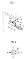
- Fig. 1 shows a conventional pressure-connecting terminal 10 disclosed in Unexamined Japanese Utility Model Publication No. Hei. 4-15159.
- the pressure-connecting terminal 10 is designed so that pressure-connecting blades 10d and pressure-connecting blades 10e rip off an insulating layer 11a of a sheathed wire 11 to be connected to a conductor 11b of the sheathed wire 11. That is, the sheathed wire 11 is laid horizontal between a pair of side walls 10c so as to be press-connected from above, the side walls 10c being bent from a bottom wall 10b of a pressure-connecting portion 10a so as to confront each other.
- the pressure-connecting blades 10d that form a U-shaped pressure-connecting slot 10f while bent inward from the side walls 10c and the pressure-connecting blades 10e that form a pressure-connecting slot 10g while bent inward from the bottom wall 10b rip off the insulating layer 11a to be connected to the conductor 11b.
- the conventional pressure-connecting terminal 10 addresses the inconvenience that the power of the pressure-connecting portion 10a for holding the sheathed wire 11 is reduced. That is, as shown in Figs. 2 and 3, if a tensile force F is applied in an axial direction from the sheathed wire 11 to the pressure-connecting blades 10d, 10e that have bitten into the sheathed wire 11, e.g., as in the case where the sheathed wire 11 is pulled in an axial direction with one end of the sheathed wire being fixed by the pressure-connecting portion 10a after the sheathed wire has been pressured, the pressure-connecting blades 10e, 10e are bent or fallen off, and such deformation of the pressure-connecting blades 10d, 10e leads to the aforementioned reduction in holding power.
- the thickness of the pressure-connecting terminal is increased, the weight of the pressure-connecting terminal is also increased, whereas if a reinforcing member is arranged, the problem that the manufacturing process becomes complicated in the sense that a separate reinforcing member must be additionally provided on the small-sized pressure-connecting terminal 10.
- a pressure-connecting terminal that includes: a bottom wall; a pair of side walls being bent from the bottom wall so as to confront each other; and a pressure-connecting portion having pressure-connecting blades on either one or both of the bottom wall and the side walls so that the pressure-connecting blades form pressure-connecting slots while bent inward, the pressure-connecting terminal allowing the pressure-connecting blades to rip off an insulating layer of a sheathed wire to be connected to a conductor of the sheathed wire when the sheathed wire is press-connected into the pressure-connecting slots.
- beads are formed over corner portions continuously extending from the pressure-connecting blades to the side walls or the bottom wall so as to protrude inward from outside.
- the rigidity of the pressure-connecting blades is increased by the beads that are formed over the corner portions continuously extending from the pressure-connecting blades to the side walls or the bottom wall so as to protrude inward from outside.
- the pressure-connecting blades are formed so as to be bent from both of the pair of side walls; and the beads are formed over corner portions continuously extending from both pressure-connecting blades to the pair of side walls.
- the sheathed wire can be held stably from both sides thereof by the pressure-connecting blades, in addition to the operation performed by the aforementioned invention.
- the pressure-connecting blades formed so as to be bent from both side walls are paired so as to extend in an axial direction at a distance from each other along the side walls.
- a plurality of pressure-connecting blades can operate onto the sheathed wire in the axial direction, in addition to the operation performed by the aforementioned invention.
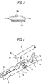
- reference numeral 1 denotes a pressure-connecting terminal, which is formed by press-working a conductive plate member into such a shape that a connecting portion 1a, a pressure-connecting portion 1b, and a caulking portion 1c are arranged continuously from one side to the other.
- the connecting portion 1a connects a not shown mating terminal thereto.
- the pressure-connecting portion 1b pressures a sheathed wire 2 that has a conductor 2a sheathed by an insulating layer 2b.
- the caulking portion 1c caulks the sheathed wire 2.
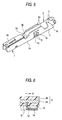
- the pressure-connecting portion 1b includes: a bottom wall 1d: a pair of side walls 1e that are bent from the bottom wall 1d so as to confront each other; pressure-connecting blades 1f that are bent from these side walls 1e so as to open like French doors; and beads 1g that are formed over corner portions continuously extending from the side walls 1e to the pressure-connecting blades 1f so as to protrude inward from outside.
- Pressure-connecting slots 1h are formed between the pressure-connecting blades 1f extending from the side wall 1e on one side and the pressure-connecting blades 1f extending from the side wall 1e on the other side.
- the caulking portion 1c has a bottom wall 1k and a pair of side walls 1i that are extended from the bottom wall 1d and the pair of side walls 1e of the pressure-connecting portion 1b, forming caulking pieces 1j that are erect alternately.
- an end portion of the sheathed wire 2 is press-connected into the pressure-connecting slots 1h horizontal from above between the side walls 1i of the caulking portion 1c and the side walls 1e of the pressure-connecting portion 1b, so that the pressure-connecting blades 1f rip off the insulating layer 2b of the sheathed wire 2 to be connected to the conductor 2a while biting into the conductor 2a.
- the sheathed wire 2 is supported so as to be crimped by the caulking pieces 1j.
- the pressure-connecting blades 1f whose rigidity has been increased by the beads 1g can hold the sheathed wire 2 stably from both sides of the sheathed wire.
- the pressure-connecting blades 1f whose rigidity has been increased can hold the sheathed wire 2 more strongly while extending at a distance from each other in the axial direction along the pair of side walls 1e.
- pressure-connecting blades 1f are bent from the respective side walls 1e in the aforementioned embodiment, similar operation and advantageous effects can be obtained by bending not shown pressure-connecting blades inward from the bottom wall 1d, or by bending not shown pressure-connecting blades inward from both the side walls 1e and the bottom wall 1d.
- the invention provides the following advantageous effects.
- the rigidity of the pressure-connecting blades is increased by the beads that are formed over the corner portions continuously extending from the pressure-connecting blades to the side walls or the bottom wall so as to protrude inward from outside.
- the sheathed wire can be held stably from both sides thereof by the pressure-connecting blades.
- the sheathed wire can be held strongly by the pressure-connecting blades.
Abstract
Description
Claims (3)
- A pressure-connecting terminal including: a bottom wall; a pair of side walls being bent from the bottom wall so as to confront each other; and a pressure-connecting portion having pressure-connecting blades on either one or both of the bottom wall and the side walls so that the pressure-connecting blades form pressure-connecting slots while bent inward, the pressure-connecting terminal allowing the pressure-connecting blades to rip off an insulating layer of a sheathed wire to be connected to a conductor of the sheathed wire when the sheathed wire is press-connected into the pressure-connecting slots,
wherein beads are formed over corner portions continuously extending from the pressure-connecting blades to the side walls or the bottom wall so as to protrude inward from outside. - A pressure-connecting terminal according to claim 1, wherein the pressure-connecting blades are formed so as to be bent from both of the pair of side walls; and the beads are formed over corner portions continuously extending from both pressure-connecting blades to the pair of side walls.
- A pressure-connecting terminal according to claim 2, wherein the pressure-connecting blades formed so as to be bent from both side walls are paired so as to extend in an axial direction at a distance from each other along the side walls.
Applications Claiming Priority (3)
| Application Number | Priority Date | Filing Date | Title |
|---|---|---|---|
| JP34827096A JP3247060B2 (en) | 1996-12-26 | 1996-12-26 | ID terminal |
| JP348270/96 | 1996-12-26 | ||
| JP34827096 | 1996-12-26 |
Publications (2)
| Publication Number | Publication Date |
|---|---|
| EP0851534A2 true EP0851534A2 (en) | 1998-07-01 |
| EP0851534A3 EP0851534A3 (en) | 1999-06-16 |
Family
ID=18395910
Family Applications (1)
| Application Number | Title | Priority Date | Filing Date |
|---|---|---|---|
| EP97122666A Ceased EP0851534A3 (en) | 1996-12-26 | 1997-12-22 | Pressure connecting terminal |
Country Status (5)
| Country | Link |
|---|---|
| US (1) | US5964612A (en) |
| EP (1) | EP0851534A3 (en) |
| JP (1) | JP3247060B2 (en) |
| KR (1) | KR100267909B1 (en) |
| CN (1) | CN1133238C (en) |
Cited By (1)
| Publication number | Priority date | Publication date | Assignee | Title |
|---|---|---|---|---|
| US6796830B2 (en) | 2001-04-20 | 2004-09-28 | Wieland Electric Gmbh | Screwless connecting terminal |
Families Citing this family (6)
| Publication number | Priority date | Publication date | Assignee | Title |
|---|---|---|---|---|
| JP4555223B2 (en) * | 2003-06-18 | 2010-09-29 | 三菱電線工業株式会社 | Connecting terminal |
| US7347717B2 (en) * | 2006-04-12 | 2008-03-25 | Illinois Tool Works | Insulation displacement system |
| JP5359975B2 (en) | 2010-04-07 | 2013-12-04 | 住友電装株式会社 | Terminal fitting |
| JP2014093120A (en) * | 2012-10-31 | 2014-05-19 | Tyco Electronics Japan Kk | Pressure contacting contact and connector |
| JP6357334B2 (en) | 2014-03-28 | 2018-07-11 | 矢崎総業株式会社 | Connection structure of crimp terminal and electric wire |
| JP6547683B2 (en) * | 2016-05-26 | 2019-07-24 | 株式会社村田製作所 | Coil parts |
Citations (3)
| Publication number | Priority date | Publication date | Assignee | Title |
|---|---|---|---|---|
| US4699441A (en) * | 1984-09-14 | 1987-10-13 | Amp Incorporated | Electrical connector for stranded wires |
| US5554046A (en) * | 1993-12-24 | 1996-09-10 | Yazaki Corporation | Solderless terminal |
| WO1996033523A1 (en) * | 1995-04-21 | 1996-10-24 | The Whitaker Corporation | Insulation displacement contact with strain relief |
Family Cites Families (5)
| Publication number | Priority date | Publication date | Assignee | Title |
|---|---|---|---|---|
| US4527852A (en) * | 1983-08-09 | 1985-07-09 | Molex Incorporated | Multigauge insulation displacement connector and contacts therefor |
| JPH0524131Y2 (en) * | 1986-11-07 | 1993-06-18 | ||
| GB8703551D0 (en) * | 1987-02-16 | 1987-03-25 | Amp Great Britain | Electrical terminal |
| JPH0415159A (en) * | 1990-05-08 | 1992-01-20 | Toshiba Corp | Automatic door closing device of train |
| JP2885258B2 (en) * | 1992-09-11 | 1999-04-19 | 矢崎総業株式会社 | ID terminal fitting |
-
1996
- 1996-12-26 JP JP34827096A patent/JP3247060B2/en not_active Expired - Fee Related
-
1997
- 1997-12-19 US US08/995,142 patent/US5964612A/en not_active Expired - Fee Related
- 1997-12-22 EP EP97122666A patent/EP0851534A3/en not_active Ceased
- 1997-12-24 CN CN97129761A patent/CN1133238C/en not_active Expired - Fee Related
- 1997-12-24 KR KR1019970072884A patent/KR100267909B1/en not_active IP Right Cessation
Patent Citations (3)
| Publication number | Priority date | Publication date | Assignee | Title |
|---|---|---|---|---|
| US4699441A (en) * | 1984-09-14 | 1987-10-13 | Amp Incorporated | Electrical connector for stranded wires |
| US5554046A (en) * | 1993-12-24 | 1996-09-10 | Yazaki Corporation | Solderless terminal |
| WO1996033523A1 (en) * | 1995-04-21 | 1996-10-24 | The Whitaker Corporation | Insulation displacement contact with strain relief |
Cited By (1)
| Publication number | Priority date | Publication date | Assignee | Title |
|---|---|---|---|---|
| US6796830B2 (en) | 2001-04-20 | 2004-09-28 | Wieland Electric Gmbh | Screwless connecting terminal |
Also Published As
| Publication number | Publication date |
|---|---|
| KR19980064542A (en) | 1998-10-07 |
| CN1133238C (en) | 2003-12-31 |
| JPH10189073A (en) | 1998-07-21 |
| US5964612A (en) | 1999-10-12 |
| KR100267909B1 (en) | 2000-10-16 |
| EP0851534A3 (en) | 1999-06-16 |
| JP3247060B2 (en) | 2002-01-15 |
| CN1192064A (en) | 1998-09-02 |
Similar Documents
| Publication | Publication Date | Title |
|---|---|---|
| JP2935165B2 (en) | Assembly method and structure of press-fit joint connector | |
| JPH0716313Y2 (en) | Electrical connector | |
| JP3262211B2 (en) | ID connector | |
| JPH0357018Y2 (en) | ||
| JP3478010B2 (en) | Male terminal fitting | |
| EP0851534A2 (en) | Pressure connecting terminal | |
| US6193138B1 (en) | Pressure welding device and method for terminals | |
| US6997761B2 (en) | Electrical contact element | |
| US5947774A (en) | Press-connecting connector | |
| KR100270844B1 (en) | Crimping terninal | |
| JPH0982391A (en) | Terminal metal fitting and manufacture of terminal metal fitting | |
| JP3478022B2 (en) | Male terminal fitting | |
| JP2849899B2 (en) | ID terminal structure | |
| US5951326A (en) | Connector and connector assembling method | |
| JPH0412616Y2 (en) | ||
| JP3300251B2 (en) | ID connector | |
| JP2001135368A (en) | Housing for pressure joint terminal and joint connector using the same | |
| US5830004A (en) | Press-connecting terminal | |
| JPH05251143A (en) | Junction terminal for connecting male terminal | |
| JP2576858Y2 (en) | connector | |
| JPH02299176A (en) | Split type connector with split terminal | |
| JPS6345738Y2 (en) | ||
| JP2603861Y2 (en) | ID connector | |
| JP3314846B2 (en) | Interconnection terminals and joint connectors | |
| JP3060371B2 (en) | Connector housing structure |
Legal Events
| Date | Code | Title | Description |
|---|---|---|---|
| PUAI | Public reference made under article 153(3) epc to a published international application that has entered the european phase |
Free format text: ORIGINAL CODE: 0009012 |
|
| AK | Designated contracting states |
Kind code of ref document: A2 Designated state(s): DE FR GB |
|
| AX | Request for extension of the european patent |
Free format text: AL;LT;LV;MK;RO;SI |
|
| PUAL | Search report despatched |
Free format text: ORIGINAL CODE: 0009013 |
|
| AK | Designated contracting states |
Kind code of ref document: A3 Designated state(s): AT BE CH DE DK ES FI FR GB GR IE IT LI LU MC NL PT SE |
|
| AX | Request for extension of the european patent |
Free format text: AL;LT;LV;MK;RO;SI |
|
| 17P | Request for examination filed |
Effective date: 19990819 |
|
| AKX | Designation fees paid |
Free format text: DE FR GB |
|
| 17Q | First examination report despatched |
Effective date: 20020403 |
|
| STAA | Information on the status of an ep patent application or granted ep patent |
Free format text: STATUS: THE APPLICATION HAS BEEN REFUSED |
|
| 18R | Application refused |
Effective date: 20030522 |