EP0851177A1 - Elastomer sealing gasket particularly for cooking oven doors - Google Patents
Elastomer sealing gasket particularly for cooking oven doors Download PDFInfo
- Publication number
- EP0851177A1 EP0851177A1 EP96120322A EP96120322A EP0851177A1 EP 0851177 A1 EP0851177 A1 EP 0851177A1 EP 96120322 A EP96120322 A EP 96120322A EP 96120322 A EP96120322 A EP 96120322A EP 0851177 A1 EP0851177 A1 EP 0851177A1
- Authority
- EP
- European Patent Office
- Prior art keywords
- gasket
- opening
- continuous strip
- oven
- gasket according
- Prior art date
- Legal status (The legal status is an assumption and is not a legal conclusion. Google has not performed a legal analysis and makes no representation as to the accuracy of the status listed.)
- Granted
Links
Images

Classifications
-
- F—MECHANICAL ENGINEERING; LIGHTING; HEATING; WEAPONS; BLASTING
- F24—HEATING; RANGES; VENTILATING
- F24C—DOMESTIC STOVES OR RANGES ; DETAILS OF DOMESTIC STOVES OR RANGES, OF GENERAL APPLICATION
- F24C15/00—Details
- F24C15/02—Doors specially adapted for stoves or ranges
- F24C15/021—Doors specially adapted for stoves or ranges sealings for doors or transparent panel
Definitions
- the present invention relates to an elastomer sealing gasket, in particular of silicone rubber, particularly for cooking oven doors.
- gaskets can be of the closed frame type, that is made up of four sides joined together to form a rectangle, or of the three-sided open-frame type, that is lacking the bottom side, the area in which there is normally less heat loss.
- the gaskets currently used are obtained by bending, and possibly joining at the ends, a single hollow strip with hooking means situated at least in the areas where the strip is bent, that is at the corners of the frame.
- Metal inserts with a widened base which is inserted in a corresponding opening made in the flat bottom wall of the gasket are used as hooking means.
- Said widened base of the corner insert is arched into a semi-elliptical shape and is inserted, almost always manually, into the hollow of the gasket through the opening provided in the bottom of the gasket itself.
- a hook which engages in a corresponding hole provided in the oven structure protrudes from the base of the metal insert, through said opening.
- two metal end inserts are provided that are inserted through the ends of the gasket and are normally fixed with adhesive.
- a gasket of this type is described for example in GB-A-2 106 974.
- a first drawback is that the gasket can easily tear at the ends of the cut, especially at the time of insertion of the metal insert, and consequently an adhesive must be used to hold the hook in position and prevent the tear from extending during use of the gasket.
- slots for insertion of the metal inserts with hooks are made in the hollow gasket strip by removing material.
- Such a solution eliminates the problem of tearing of the gasket, but introduces other drawbacks, such as, for example, the greater complexity of the equipment that has to make the slot and, at the same time, remove the material enclosed by the outline of the slot, for example by vacuum means.
- Another drawback of this solution is that, if an adhesive is not used to fix the insert and thus close the slot, material from outside such as grease and the like tends to accumulate there, stagnating in the gasket and soiling it.
- the aim of the invention is to eliminate the aforementioned disadvantages and in particular to solve the problems of the solution described in GB-A-2 106 974, which provides for a straight cut in the gasket, without introducing further problems, such as those of the solution proposed in EP-A-277 098, for example.
- Another aim of this invention is to provide a gasket of this type, in which said openings stay covered during use of the gasket, preventing oven materials from entering the gasket,
- Yet another aim of the invention is to provide an opening that adapts well to the outline of the metal insert.
- Yet another aim of the invention is to provide such a gasket, in which the metal inserts can be mounted with or without the use of an adhesive.
- the opening made in the gasket to accommodate the metal insert consists of a cut with rounded ends, so as to prevent initiation of tearing.
- the portion joining said rounded ends of the cut advantageously has a curved shape that follows the curved contour of the base of the corner inserts, that is of the inserts suitable to be placed at the corners of the oven door.
- the gasket for cooking ovens comprises a continuous strip 1 made of an elastomer, in particular silicone rubber, and a plurality of metal elements 2, 2', 2'', the function of which will be described below.
- the continuous strip 1, obtained by extrusion, is of the tubular type and has a continuous inner cavity 3, defined on one side by a flat surface 4, at the longitudinal edges of which respective lips 5 are provided to improve the seal against the surface on which the gasket is applied.
- a protruding longitudinal flap 7 is provided which, in the specific case, encloses a second continuous cavity 6.
- the purpose of the flap 7 is to provide a tight seal against the complementary element of the oven where the gasket is interposed, in particular against the oven door.
- the flap 7 can equally well be oriented so that it is directed either towards the insides of the frame, as illustrated in the appended figures, or towards the outside.
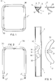
- Figure 1 schematically shows a gasket 10 with four sides, forming a closed rectangular frame
- Figure 2 schematically illustrates a gasket 100 with three sides, forming an open frame without the bottom side.
- the aforementioned metal hooking elements 2, 2' are used to fix the gaskets to the corresponding wall of the oven, whilst the metal element 2'', shown hatched in Figure 1, acts as a joining element to make the join at the ends of the closed-frame gasket 10, in Figure 1, being inserted axially into the tubular chamber 3 of the gasket at the ends thereof and being fixed there with a suitable adhesive.
- the metal inserts 2' used in the three-sided gasket in Figure 2, are also inserted axially, from the ends of the gasket, into the tubular chamber 3 thereof, and fixed with suitable adhesive. These metal inserts 2' have a respective hook 21' at one end, lying along the longitudinal axis of the insert 2', for hooking into corresponding holes provided on the base of the oven.
- the metal insert 2 has a flat base 20, with an arched profile, with a recess 22 in the centre of the concave inner profile, from which a hook 21 protrudes, designed to engage in a corresponding hole in the oven structure, like the hooks 21' of the end inserts 2'.
- each opening 30, is made in the flat wall 4 defining said chamber.
- Each opening 30, as can be seen more clearly in the plan view in Figure 3, consists of a continuous cut, advantageously made by die-cutting, comprising an intermediate portion 31, extending substantially in the longitudinal direction of the strip 1, and two terminal portions 32, with a rounded outline, advantageously shaped like the arc of a circle, for an extension greater than 180°, or at least 90°.
- the intermediate portion 31 also has a curved shape, with a curvature that follows that of the base 20 of the metal insert 2, and with a concavity advantageously facing in the direction in which the strip 1 is bent to form the corner of the gasket, as shown, for example, in Figure 4.
- This shaping of the opening 30 solves the problems described in the preamble of this description.
- the rounded ends 32 of the cut facilitate insertion of the base 20 of the inserts 2, preventing tearing of the gasket during insertion, which requires a considerable elastic stretching of the material, since the opening 30 is smaller than the size of the insert 2.
- Adhesive can also be optionally provided to fix the inserts 2 in the corresponding openings 30.
- the cuts 30 made in the gasket can also be used for insertion of metal inserts with a straight instead of a curved base, for example of inserts to be placed at intermediate points, instead of at the corners, of the gaskets 10, 100.
- Two of such intermediate inserts have been schematically illustrated in Figures 1 and 2, and with these the same advantages are achieved. as those described previously with reference to the corner inserts
Abstract
Description
Claims (10)
- A sealing gasket made of an elastomer particularly for cooking ovens, to be interposed between a front rim of the oven and a corresponding door, said gasket comprising a continuous strip (1), provided with metal inserts (2, 2'), having hooks (21, 21') able to engage in holes provided in the oven structure, said metal inserts (2) being inserted in a tubular cavity (3) of said continuous strip (1), through respective openings (30) made in a flat wall (4), defining said tubular cavity (3) on one side, characterized in that each of said openings (30) consists of a continuous cut comprising an intermediate portion (31) extending substantially in the longitudinal direction of the strip (1), and two respective end portions (32) with a curved outline.
- A gasket according to claim 1, characterized in that said end portions (32) with a curved outline are arcs of a circle.
- A gasket according to claim 2, characterized in that said terminal portions (32) shaped like an arc of a circle extend over an angle greater than 90°.
- A gasket according to any one of the preceding claims, characterized in that said intermediate potion (31) of the opening (30) has an arched outline.
- A gasket according to claim 4, characterized in that said intermediate portion (31) of the opening (30) with an arched outline has its concavity facing in the direction in which the continuous strip (1) is bent to form a gasket (10, 100).
- A gasket according to any one of the preceding claims, characterized in that said metal inserts (2) have a base (20) with a curved profile, and are suitable to be placed at the corners of said gasket (10, 100).
- A gasket according to any one of claims 1 to 5, characterized in that said metal inserts (2) have a straight base and are suitable to be placed at intermediate points along the sides of the gasket (10, 100).
- A gasket according to any one of the preceding claims, characterized in that said continuous cut of each opening (30) defines a flap of material (33) that remains in place and keeps said opening closed during use of the gasket (10, 100).
- A gasket according to claim 1, in which said metal inserts (2') are inserted from the two ends of said continuous strip (1) which is bent to form a three-sided open gasket (100).
- An opening (30) for insertion of a metal insert (2) in a tubular cavity (3) of a gasket (10, 100) for cooking ovens, obtained by bending a continuous strip (1) characterized in that said opening (30) comprises an intermediate portion (31) substantially extending longitudinally to said continuous strip (1) and two end portions (32) with a rounded outline, defining a flap of material (33) that remains in position on the gasket and keeps said opening (30) closed during use.
Priority Applications (5)
| Application Number | Priority Date | Filing Date | Title |
|---|---|---|---|
| DE69611683T DE69611683T2 (en) | 1996-12-18 | 1996-12-18 | Elastomer seal, especially for oven door |
| ES96120322T ES2154380T3 (en) | 1996-12-18 | 1996-12-18 | SEALING SEAL OF ELASTOMERO ADEQUATE IN PARTICULAR FOR DOORS OF KITCHEN OVENS. |
| AT96120322T ATE198931T1 (en) | 1996-12-18 | 1996-12-18 | ELASTOMER SEAL, ESPECIALLY FOR OVEN DOOR |
| PT96120322T PT851177E (en) | 1996-12-18 | 1996-12-18 | ELASTOMER SEAL JOINT PARTICULARLY FOR KITCHEN OVEN DOORS |
| EP96120322A EP0851177B1 (en) | 1996-12-18 | 1996-12-18 | Elastomer sealing gasket particularly for cooking oven doors |
Applications Claiming Priority (1)
| Application Number | Priority Date | Filing Date | Title |
|---|---|---|---|
| EP96120322A EP0851177B1 (en) | 1996-12-18 | 1996-12-18 | Elastomer sealing gasket particularly for cooking oven doors |
Publications (2)
| Publication Number | Publication Date |
|---|---|
| EP0851177A1 true EP0851177A1 (en) | 1998-07-01 |
| EP0851177B1 EP0851177B1 (en) | 2001-01-24 |
Family
ID=8223511
Family Applications (1)
| Application Number | Title | Priority Date | Filing Date |
|---|---|---|---|
| EP96120322A Expired - Lifetime EP0851177B1 (en) | 1996-12-18 | 1996-12-18 | Elastomer sealing gasket particularly for cooking oven doors |
Country Status (5)
| Country | Link |
|---|---|
| EP (1) | EP0851177B1 (en) |
| AT (1) | ATE198931T1 (en) |
| DE (1) | DE69611683T2 (en) |
| ES (1) | ES2154380T3 (en) |
| PT (1) | PT851177E (en) |
Cited By (3)
| Publication number | Priority date | Publication date | Assignee | Title |
|---|---|---|---|---|
| EP0859196A1 (en) | 1997-02-12 | 1998-08-19 | Siliconas Silam, S.A. | Elastomeric material frame-shaped joint, especially for oven doors |
| US7549305B2 (en) * | 2002-07-31 | 2009-06-23 | Lg Electronics Inc. | Door on drum type washing machine or laundry dryer |
| EP2837893A1 (en) * | 2013-08-14 | 2015-02-18 | Electrolux Appliances Aktiebolag | Cooking appliance with a gasket |
Families Citing this family (1)
| Publication number | Priority date | Publication date | Assignee | Title |
|---|---|---|---|---|
| DE102004032931A1 (en) * | 2004-07-07 | 2006-02-02 | BSH Bosch und Siemens Hausgeräte GmbH | Oven with a oven door seal |
Citations (3)
| Publication number | Priority date | Publication date | Assignee | Title |
|---|---|---|---|---|
| GB2106974A (en) | 1981-10-06 | 1983-04-20 | Silicone Altimex Ltd | Door seal |
| GB2113827A (en) * | 1982-01-23 | 1983-08-10 | Silicone Fabrications Limited | Stretch gaskets |
| EP0277098A2 (en) | 1987-01-21 | 1988-08-03 | GIAT S.r.L. | Improved gasket of elastomer material in the form of a closed or open frame for cooking oven doors |
-
1996
- 1996-12-18 AT AT96120322T patent/ATE198931T1/en not_active IP Right Cessation
- 1996-12-18 DE DE69611683T patent/DE69611683T2/en not_active Expired - Lifetime
- 1996-12-18 EP EP96120322A patent/EP0851177B1/en not_active Expired - Lifetime
- 1996-12-18 PT PT96120322T patent/PT851177E/en unknown
- 1996-12-18 ES ES96120322T patent/ES2154380T3/en not_active Expired - Lifetime
Patent Citations (3)
| Publication number | Priority date | Publication date | Assignee | Title |
|---|---|---|---|---|
| GB2106974A (en) | 1981-10-06 | 1983-04-20 | Silicone Altimex Ltd | Door seal |
| GB2113827A (en) * | 1982-01-23 | 1983-08-10 | Silicone Fabrications Limited | Stretch gaskets |
| EP0277098A2 (en) | 1987-01-21 | 1988-08-03 | GIAT S.r.L. | Improved gasket of elastomer material in the form of a closed or open frame for cooking oven doors |
Cited By (5)
| Publication number | Priority date | Publication date | Assignee | Title |
|---|---|---|---|---|
| EP0859196A1 (en) | 1997-02-12 | 1998-08-19 | Siliconas Silam, S.A. | Elastomeric material frame-shaped joint, especially for oven doors |
| ES2142715A1 (en) * | 1997-02-12 | 2000-04-16 | Alberto Manero S A | Elastomeric material frame-shaped joint, especially for oven doors |
| US7549305B2 (en) * | 2002-07-31 | 2009-06-23 | Lg Electronics Inc. | Door on drum type washing machine or laundry dryer |
| US7730749B2 (en) | 2002-07-31 | 2010-06-08 | Lg Electronics Inc. | Door on drum type washing machine or laundry dryer |
| EP2837893A1 (en) * | 2013-08-14 | 2015-02-18 | Electrolux Appliances Aktiebolag | Cooking appliance with a gasket |
Also Published As
| Publication number | Publication date |
|---|---|
| DE69611683T2 (en) | 2001-08-02 |
| ES2154380T3 (en) | 2001-04-01 |
| DE69611683D1 (en) | 2001-03-01 |
| EP0851177B1 (en) | 2001-01-24 |
| ATE198931T1 (en) | 2001-02-15 |
| PT851177E (en) | 2001-07-31 |
Similar Documents
| Publication | Publication Date | Title |
|---|---|---|
| CA1284162C (en) | Automobile weatherstripping | |
| US5560731A (en) | Plug connector for hollow sections | |
| EP0448270B1 (en) | Glass run channel weather strip | |
| CA2240552A1 (en) | Automotive door seal | |
| EP0519856A1 (en) | Structure for the watertight assembly of plates on roofs and the like | |
| EP0851177B1 (en) | Elastomer sealing gasket particularly for cooking oven doors | |
| WO1999019223A1 (en) | Hinged clip | |
| US5709390A (en) | Elastomeric sealing gasket for cooking oven doors | |
| EP1098026A3 (en) | Gasket for a laundry washing machine door | |
| EP0992740B1 (en) | Elastomeric sealing gasket for cooking ovens | |
| EP0277098B1 (en) | Improved gasket of elastomer material in the form of a closed or open frame for cooking oven doors | |
| KR19980063349A (en) | Improved low profile earless clamp | |
| JPH01118086A (en) | Door body for refrigerator | |
| ES288928U (en) | Door sealing for a baking oven. | |
| MY126784A (en) | Microwave oven | |
| WO2002049867A1 (en) | Sealing, trimming and finishing strips | |
| GB2322073A (en) | Cover for domestic appliance | |
| GB2034018A (en) | Header Tank Construction | |
| EP1257771B1 (en) | Counter-door frame with gasket for domestic cooking ovens | |
| GB2295186A (en) | Drain clip for a vehicle weatherstrip and a vehicle weatherstrip with a drain clip | |
| EP0974795A2 (en) | Sealing joint for a refrigerator door | |
| EP2035752B1 (en) | An oven | |
| GB2026067A (en) | Seal gasket | |
| JP3660411B2 (en) | Drip weather strip | |
| KR0180766B1 (en) | Microwave leakage shielding door for microwave oven |
Legal Events
| Date | Code | Title | Description |
|---|---|---|---|
| PUAI | Public reference made under article 153(3) epc to a published international application that has entered the european phase |
Free format text: ORIGINAL CODE: 0009012 |
|
| AK | Designated contracting states |
Kind code of ref document: A1 Designated state(s): AT DE ES FR GB IT NL PT SE |
|
| AX | Request for extension of the european patent |
Free format text: AL;LT;LV;RO;SI |
|
| 17P | Request for examination filed |
Effective date: 19980718 |
|
| AKX | Designation fees paid |
Free format text: DE FR IT |
|
| RBV | Designated contracting states (corrected) |
Designated state(s): DE FR IT |
|
| RBV | Designated contracting states (corrected) |
Designated state(s): AT DE ES FR GB IT NL PT SE |
|
| RBV | Designated contracting states (corrected) |
Designated state(s): AT DE ES FR GB IT NL PT SE |
|
| 17Q | First examination report despatched |
Effective date: 20000322 |
|
| GRAG | Despatch of communication of intention to grant |
Free format text: ORIGINAL CODE: EPIDOS AGRA |
|
| GRAG | Despatch of communication of intention to grant |
Free format text: ORIGINAL CODE: EPIDOS AGRA |
|
| GRAH | Despatch of communication of intention to grant a patent |
Free format text: ORIGINAL CODE: EPIDOS IGRA |
|
| GRAA | (expected) grant |
Free format text: ORIGINAL CODE: 0009210 |
|
| AK | Designated contracting states |
Kind code of ref document: B1 Designated state(s): AT DE ES FR GB IT NL PT SE |
|
| PG25 | Lapsed in a contracting state [announced via postgrant information from national office to epo] |
Ref country code: SE Free format text: LAPSE BECAUSE OF FAILURE TO SUBMIT A TRANSLATION OF THE DESCRIPTION OR TO PAY THE FEE WITHIN THE PRESCRIBED TIME-LIMIT Effective date: 20010124 Ref country code: NL Free format text: LAPSE BECAUSE OF FAILURE TO SUBMIT A TRANSLATION OF THE DESCRIPTION OR TO PAY THE FEE WITHIN THE PRESCRIBED TIME-LIMIT Effective date: 20010124 |
|
| REF | Corresponds to: |
Ref document number: 198931 Country of ref document: AT Date of ref document: 20010215 Kind code of ref document: T |
|
| ITF | It: translation for a ep patent filed |
Owner name: RACHELI & C. S.R.L. |
|
| REF | Corresponds to: |
Ref document number: 69611683 Country of ref document: DE Date of ref document: 20010301 |
|
| REG | Reference to a national code |
Ref country code: ES Ref legal event code: FG2A Ref document number: 2154380 Country of ref document: ES Kind code of ref document: T3 |
|
| ET | Fr: translation filed | ||
| NLV1 | Nl: lapsed or annulled due to failure to fulfill the requirements of art. 29p and 29m of the patents act | ||
| REG | Reference to a national code |
Ref country code: PT Ref legal event code: SC4A Free format text: AVAILABILITY OF NATIONAL TRANSLATION Effective date: 20010418 |
|
| PLBQ | Unpublished change to opponent data |
Free format text: ORIGINAL CODE: EPIDOS OPPO |
|
| PLBI | Opposition filed |
Free format text: ORIGINAL CODE: 0009260 |
|
| PLBF | Reply of patent proprietor to notice(s) of opposition |
Free format text: ORIGINAL CODE: EPIDOS OBSO |
|
| 26 | Opposition filed |
Opponent name: GIAT S.P.A. Effective date: 20011019 |
|
| REG | Reference to a national code |
Ref country code: GB Ref legal event code: IF02 |
|
| PLBF | Reply of patent proprietor to notice(s) of opposition |
Free format text: ORIGINAL CODE: EPIDOS OBSO |
|
| PLBO | Opposition rejected |
Free format text: ORIGINAL CODE: EPIDOS REJO |
|
| PLBN | Opposition rejected |
Free format text: ORIGINAL CODE: 0009273 |
|
| STAA | Information on the status of an ep patent application or granted ep patent |
Free format text: STATUS: OPPOSITION REJECTED |
|
| 27O | Opposition rejected |
Effective date: 20020716 |
|
| PGFP | Annual fee paid to national office [announced via postgrant information from national office to epo] |
Ref country code: ES Payment date: 20071205 Year of fee payment: 12 |
|
| PGFP | Annual fee paid to national office [announced via postgrant information from national office to epo] |
Ref country code: AT Payment date: 20071227 Year of fee payment: 12 |
|
| PGFP | Annual fee paid to national office [announced via postgrant information from national office to epo] |
Ref country code: PT Payment date: 20071122 Year of fee payment: 12 |
|
| REG | Reference to a national code |
Ref country code: PT Ref legal event code: MM4A Free format text: LAPSE DUE TO NON-PAYMENT OF FEES Effective date: 20090618 |
|
| PG25 | Lapsed in a contracting state [announced via postgrant information from national office to epo] |
Ref country code: PT Free format text: LAPSE BECAUSE OF NON-PAYMENT OF DUE FEES Effective date: 20090618 Ref country code: AT Free format text: LAPSE BECAUSE OF NON-PAYMENT OF DUE FEES Effective date: 20081218 |
|
| REG | Reference to a national code |
Ref country code: ES Ref legal event code: FD2A Effective date: 20081219 |
|
| PG25 | Lapsed in a contracting state [announced via postgrant information from national office to epo] |
Ref country code: ES Free format text: LAPSE BECAUSE OF NON-PAYMENT OF DUE FEES Effective date: 20081219 |
|
| PGRI | Patent reinstated in contracting state [announced from national office to epo] |
Ref country code: IT Effective date: 20110501 |
|
| PGFP | Annual fee paid to national office [announced via postgrant information from national office to epo] |
Ref country code: IT Payment date: 20121221 Year of fee payment: 17 Ref country code: GB Payment date: 20121128 Year of fee payment: 17 |
|
| PGFP | Annual fee paid to national office [announced via postgrant information from national office to epo] |
Ref country code: FR Payment date: 20121214 Year of fee payment: 17 |
|
| PGFP | Annual fee paid to national office [announced via postgrant information from national office to epo] |
Ref country code: DE Payment date: 20121227 Year of fee payment: 17 |
|
| REG | Reference to a national code |
Ref country code: DE Ref legal event code: R119 Ref document number: 69611683 Country of ref document: DE |
|
| GBPC | Gb: european patent ceased through non-payment of renewal fee |
Effective date: 20131218 |
|
| REG | Reference to a national code |
Ref country code: FR Ref legal event code: ST Effective date: 20140829 |
|
| REG | Reference to a national code |
Ref country code: DE Ref legal event code: R119 Ref document number: 69611683 Country of ref document: DE Effective date: 20140701 |
|
| PG25 | Lapsed in a contracting state [announced via postgrant information from national office to epo] |
Ref country code: DE Free format text: LAPSE BECAUSE OF NON-PAYMENT OF DUE FEES Effective date: 20140701 |
|
| PG25 | Lapsed in a contracting state [announced via postgrant information from national office to epo] |
Ref country code: FR Free format text: LAPSE BECAUSE OF NON-PAYMENT OF DUE FEES Effective date: 20131231 Ref country code: GB Free format text: LAPSE BECAUSE OF NON-PAYMENT OF DUE FEES Effective date: 20131218 |
|
| PG25 | Lapsed in a contracting state [announced via postgrant information from national office to epo] |
Ref country code: IT Free format text: LAPSE BECAUSE OF NON-PAYMENT OF DUE FEES Effective date: 20131231 |
|
| PG25 | Lapsed in a contracting state [announced via postgrant information from national office to epo] |
Ref country code: IT Free format text: LAPSE BECAUSE OF NON-PAYMENT OF DUE FEES Effective date: 20131218 |