EP0851168A2 - Vehicle headlamp - Google Patents
Vehicle headlamp Download PDFInfo
- Publication number
- EP0851168A2 EP0851168A2 EP97890224A EP97890224A EP0851168A2 EP 0851168 A2 EP0851168 A2 EP 0851168A2 EP 97890224 A EP97890224 A EP 97890224A EP 97890224 A EP97890224 A EP 97890224A EP 0851168 A2 EP0851168 A2 EP 0851168A2
- Authority
- EP
- European Patent Office
- Prior art keywords
- vehicle
- light
- lamp according
- vehicle lamp
- lamp
- Prior art date
- Legal status (The legal status is an assumption and is not a legal conclusion. Google has not performed a legal analysis and makes no representation as to the accuracy of the status listed.)
- Granted
Links
- 230000005540 biological transmission Effects 0.000 abstract description 6
- 239000000725 suspension Substances 0.000 description 3
- 239000011521 glass Substances 0.000 description 2
- 239000000463 material Substances 0.000 description 2
- 239000002184 metal Substances 0.000 description 2
- 230000003287 optical effect Effects 0.000 description 2
- 239000011257 shell material Substances 0.000 description 2
- 239000002131 composite material Substances 0.000 description 1
- 230000017525 heat dissipation Effects 0.000 description 1
- 230000005855 radiation Effects 0.000 description 1
- 238000007789 sealing Methods 0.000 description 1
- 239000012780 transparent material Substances 0.000 description 1
Images
Classifications
-
- B—PERFORMING OPERATIONS; TRANSPORTING
- B60—VEHICLES IN GENERAL
- B60Q—ARRANGEMENT OF SIGNALLING OR LIGHTING DEVICES, THE MOUNTING OR SUPPORTING THEREOF OR CIRCUITS THEREFOR, FOR VEHICLES IN GENERAL
- B60Q1/00—Arrangement of optical signalling or lighting devices, the mounting or supporting thereof or circuits therefor
- B60Q1/02—Arrangement of optical signalling or lighting devices, the mounting or supporting thereof or circuits therefor the devices being primarily intended to illuminate the way ahead or to illuminate other areas of way or environments
- B60Q1/04—Arrangement of optical signalling or lighting devices, the mounting or supporting thereof or circuits therefor the devices being primarily intended to illuminate the way ahead or to illuminate other areas of way or environments the devices being headlights
- B60Q1/06—Arrangement of optical signalling or lighting devices, the mounting or supporting thereof or circuits therefor the devices being primarily intended to illuminate the way ahead or to illuminate other areas of way or environments the devices being headlights adjustable, e.g. remotely-controlled from inside vehicle
-
- F—MECHANICAL ENGINEERING; LIGHTING; HEATING; WEAPONS; BLASTING
- F21—LIGHTING
- F21S—NON-PORTABLE LIGHTING DEVICES; SYSTEMS THEREOF; VEHICLE LIGHTING DEVICES SPECIALLY ADAPTED FOR VEHICLE EXTERIORS
- F21S41/00—Illuminating devices specially adapted for vehicle exteriors, e.g. headlamps
- F21S41/20—Illuminating devices specially adapted for vehicle exteriors, e.g. headlamps characterised by refractors, transparent cover plates, light guides or filters
- F21S41/29—Attachment thereof
-
- F—MECHANICAL ENGINEERING; LIGHTING; HEATING; WEAPONS; BLASTING
- F21—LIGHTING
- F21S—NON-PORTABLE LIGHTING DEVICES; SYSTEMS THEREOF; VEHICLE LIGHTING DEVICES SPECIALLY ADAPTED FOR VEHICLE EXTERIORS
- F21S41/00—Illuminating devices specially adapted for vehicle exteriors, e.g. headlamps
- F21S41/60—Illuminating devices specially adapted for vehicle exteriors, e.g. headlamps characterised by a variable light distribution
- F21S41/63—Illuminating devices specially adapted for vehicle exteriors, e.g. headlamps characterised by a variable light distribution by acting on refractors, filters or transparent cover plates
- F21S41/635—Illuminating devices specially adapted for vehicle exteriors, e.g. headlamps characterised by a variable light distribution by acting on refractors, filters or transparent cover plates by moving refractors, filters or transparent cover plates
Definitions
- the invention relates to a vehicle lamp, in particular vehicle headlights, with Light emission adjustment option relative to the vehicle.
- Such light emission adjustment options relative to the vehicle are diverse has been developed and usually a three-point suspension of the entire lamp Adjustability of two suspension points, or also e.g. a corresponding Three-point suspension of a reflector unit within a luminaire housing.
- the Most of these adjustment options must come from inside the body have been noticed and only recently have suggestions been made according to the control openings on the luminaire frames accessible from the outside are provided for inserting a screwdriver.
- an optical adjustment option is provided in the Beam path provided within the lamp. Accordingly, Light emission adjustment in the luminaire is slidable in the light path, in particular rotatable, radiating body with over the light emission cross section of the lamp varying thickness is provided.
- the transmission body is a prism.
- An embodiment is particularly advantageous in which the transmission body or part of the lights is the windscreen, so that this adjustment possibility of is given outside the body, preferably the lamp front window is rotatable.
- Vehicle lights with a circular light exit surface are the last More often constructed, mainly as so-called lens headlights.
- To move the radiating body is preferably a toothing provided since gears can be operated with high accuracy.
- tooth profiles can be fixed against a fixed counterpart Operate screwdriver, so the most preferred embodiment is one Vehicle lamp with circular windscreen with serration.
- the lamp as such rigidly and immovably connected to the body, in at best the reflector of the lamp.
- the single-shell is particularly preferred Training of the lamp to achieve high heat dissipation, thereby can be optimized that as a shell material, in particular as a material for the Reflector, infrared-transparent material is used.
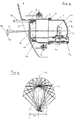
- a central vertical section through a vehicle headlight and Fig. 2 is a horizontal section through the reflector with Beam paths is.
- a light passage opening 2 is formed, behind which a Headlights 3 via brackets 4 and screws 5 cannot be adjusted on the body is screwed on.
- the headlight 3 has a rear part 7 sealed by a seal 6
- the front part of the headlight 3 is a via a seal 14 and an O-ring 15 Windscreen 16 rotatably pressed with a circular profile, so that it from outside the Body by means of an insertable into an actuating bore 17 of the headlight 3 Screwdriver 18 via a not shown serration on the windshield 16 is rotatable relative to the headlamp 3, the contact pressure of the Front disk 16 on the O-ring 15 generates a torsional resistance, so that only one Screwdriver adjustability is given.
- the thickness of the Windscreen 16 the cross-section of which is not constant, but in Fig. 1 from above increases wedge-shaped downwards.
- One along the line 19 from the light bulb 10 in the The light beam entering the front screen thus emerges as beam 20 and the angle The greater the thickness of the front pane 16, the greater the gap between the inlet and the outlet is.
- the front screen 16 can be rotated as desired relative to the headlight 3 and thus high adjustability.
- FIG. 2 shows the preferred horizontal section profile of the flat reflector 8, namely as having an asymmetrical free surface with respect to the optical axis 21 Cross-radiator characteristic, as from the filament ends shown ray paths so that the transmission diameter 22 of the Front window 16 (Figs. 1 and 2 are not on the same scale) can be kept small can.
- the front screen 16 is usually made of glass or plastic, but can can also be a composite body (central part glass, gear rim metal or plastic).
- the Varying the thickness of the front pane 16 over its cross section takes place in dependence the reflector used and the purpose of the vehicle lamp. In other words the change in thickness does not have to be continuous, e.g. no straight boundary lines result in cross section.
Landscapes
- Engineering & Computer Science (AREA)
- General Engineering & Computer Science (AREA)
- Mechanical Engineering (AREA)
- Lighting Device Outwards From Vehicle And Optical Signal (AREA)
- Non-Portable Lighting Devices Or Systems Thereof (AREA)
Abstract
Description
Die Erfindung betrifft eine Fahrzeugleuchte, insbesondere Fahrzeugscheinwerfer, mit Lichtabgabeverstellmöglichkeit relativ zum Fahrzeug.The invention relates to a vehicle lamp, in particular vehicle headlights, with Light emission adjustment option relative to the vehicle.
Derartige Lichtabgabeverstellmöglichkeiten relativ zum Fahrzeug sind vielfältig entwickelt worden und meist eine Dreipunktaufhängung der gesamten Leuchte mit Verstellbarkeit von zwei Aufhängepunkten, oder aber auch z.B. eine entsprechende Dreipunktaufhängung einer Reflektoreinheit innerhalb eines Leuchtengehäuses. Die meisten dieser Justiermöglichkeiten müssen von innerhalb der Karosserie her wahrgenommen werden und erst in letzter Zeit sind Vorschläge gemacht worden, gemäß denen an den von außen zugänglichen Leuchtenrahmen Bedienungsöffnungen zum Einfügen eines Schraubendrehers vorgesehen sind.Such light emission adjustment options relative to the vehicle are diverse has been developed and usually a three-point suspension of the entire lamp Adjustability of two suspension points, or also e.g. a corresponding Three-point suspension of a reflector unit within a luminaire housing. The Most of these adjustment options must come from inside the body have been noticed and only recently have suggestions been made according to the control openings on the luminaire frames accessible from the outside are provided for inserting a screwdriver.
Im Gegensatz dazu wird erfindungsgemäß eine optische Verstellmöglichkeit im Strahlengang innerhalb der Leuchte vorgesehen. Demgemäß ist zur Lichtabgabeverstellung in der Leuchte ein im Lichtweg verschiebbarer, insbesondere verdrehbarer, Durchstrahlkörper mit über den Lichtabgabequerschnitt der Leuchte variierender Dicke vorgesehen ist.In contrast to this, according to the invention an optical adjustment option is provided in the Beam path provided within the lamp. Accordingly, Light emission adjustment in the luminaire is slidable in the light path, in particular rotatable, radiating body with over the light emission cross section of the lamp varying thickness is provided.
Mit anderen Worten ist der Durchstrahlkörper ein Prisma.In other words, the transmission body is a prism.
Besonders vorteilhaft ist dabei eine Ausführungsform, bei der der Durchstrahlkörper die oder ein Teil der Leuchten Frontscheibe ist, sodaß diese Verstellmöglichkeit von außerhalb der Karosserie her gegeben ist, wobei bevorzugt die Leuchtenfrontscheibe verdrehbar ist. Fahrzeugleuchten mit kreisrunder Lichtaustrittsfläche werden in letzter Zeit häufiger konstruiert, hauptsächlich als sogenannte Linsenscheinwerfer.An embodiment is particularly advantageous in which the transmission body or part of the lights is the windscreen, so that this adjustment possibility of is given outside the body, preferably the lamp front window is rotatable. Vehicle lights with a circular light exit surface are the last More often constructed, mainly as so-called lens headlights.
Zur Verschiebung des Durchstrahlkörpers ist vorzugsweise eine Verzahnung vorgesehen, da Verzahnungen mit hoher Genauigkeit betätigbar sind. To move the radiating body is preferably a toothing provided since gears can be operated with high accuracy.
Insbesondere lassen sich Zahnprofile gegenüber einem festen Gegenhalt über einen Schraubendreher betätigen, deswegen ist die bevorzugteste Ausführungsform eine Fahrzeugleuchte mit kreisförmiger Frontscheibe mit Randverzahnung.In particular, tooth profiles can be fixed against a fixed counterpart Operate screwdriver, so the most preferred embodiment is one Vehicle lamp with circular windscreen with serration.
Nachdem die Lichtabgabeverstellmöglichkeit im Strahlengang der Leuchte erfolgt, kann die Leuchte als solche starr und unverstellbar mit der Karosserie verbunden werden, im günstigsten Fall der Reflektor der Leuchte. Besonders bevorzugt ist die einschalige Ausbildung der Leuchte zur Erzielung einer hohen Wärmeableitung, die dadurch optimiert werden kann, daß als Schalenmaterial, insbesondere als Material für den Reflektor, infrarotstrahlendurchlässiges Material eingesetzt wird.After the light emission adjustment option takes place in the beam path of the luminaire, the lamp as such rigidly and immovably connected to the body, in at best the reflector of the lamp. The single-shell is particularly preferred Training of the lamp to achieve high heat dissipation, thereby can be optimized that as a shell material, in particular as a material for the Reflector, infrared-transparent material is used.
Die Erfindung wird im folgenden anhand eines Ausführungsbeispiels unter Bezugnahme auf die Zeichnung näher beschrieben, in der Fig. 1 ein zentraler Vertikalschnitt durch einen Fahrzeugscheinwerfer und Fig. 2 ein Horizontalschnitt durch dessen Reflektor mit Strahlengängen ist.The invention is described below with reference to an embodiment described in more detail on the drawing, in Fig. 1, a central vertical section through a vehicle headlight and Fig. 2 is a horizontal section through the reflector with Beam paths is.
An einem Karosserieteil 1 aus üblichem Material wie Blech oder Kunststoff, und der z.B.
als Stoßfänger ausgebildet ist, ist eine Lichtdurchlaßöffnung 2 ausgebildet, hinter der ein
Scheinwerfer 3 über Laschen 4 und Schrauben 5 unverstellbar an der Karosserie
angeschraubt ist.On a
Der Scheinwerfer 3 weist einen über eine Dichtung 6 angedichteten Heckteil 7 mit
Flachreflektor 8 mit Glühlampenhalterung 9, Glühlampe 10 und Strahlenabdeckkappe
1 1 auf; 12 bezeichnet einen Zugangdeckel mit Durchlaßführung für ein Anschlußkabel
13.The
Im Vorderteil des Scheinwerfers 3 ist über eine Dichtung 14 und einen O-Ring 15 eine
Frontscheibe 16 mit Kreisprofil drehbar eingepreßt, sodaß sie von außerhalb der
Karosserie mittels eines in eine Betätigungsbohrung 17 des Scheinwerfers 3 einsteckbare
Schraubendrehers 18 über eine nicht dargestellte Randverzahnung auf der Frontscheibe
16 gegenüber dem Scheinwerfer 3 verdrehbar ist, wobei der Anpreßdruck der
Frontscheibe 16 am O-Ring 15 einen Verdrehwiderstand erzeugt, sodaß nur über einen
Schraubendreher Verstellbarkeit gegeben ist. Man erkennt, daß die Dicke der
Frontscheibe 16 über deren Querschnitt nicht konstant ist, sondern in Fig. 1 von oben
nach unten keilförmig zunimmt. Ein entlang der Linie 19 von der Glühlampe 10 in die
Frontscheibe eintretender Lichtstrahl tritt somit als Strahl 20 aus und der Winkel
zwischen Eintritt und Austritt ist umso größer, je größer die Dicke der Frontscheibe 16
ist.In the front part of the
Die Frontscheibe 16 ist gegenüber dem Scheinwerfer 3 beliebig verdrehbar und damit
eine hohe Verstellbarkeit gegeben.The
In Fig. 2 ist das bevorzugte Horizontalschnittprofil des Flachreflektors 8 gezeigt,
nämlich als zur optischen Achse 21 asymmetrische Freifläche mit
Kreuzstrahlercharakteristik, wie aus den von dem Glühfadenenden weg
eingezeichneten Strahlengängen ersichtlich, damit der Durchstrahldurchmesser 22 der
Frontscheibe 16 (die Fig. 1 und 2 sind nicht im selben Maßstab) klein gehalten werden
kann.2 shows the preferred horizontal section profile of the
Üblicherweise wird die Frontscheibe 16 aus Glas oder Kunststoff gefertigt, kann aber
auch ein Verbundkörper sein (Zentralteil Glas, Zahnkranz Metall oder Kunststoff). Die
Variation der Dicke der Frontscheibe 16 über ihren Querschnitt erfolgt in Abhängigkeit
vom verwendeten Reflektor und vom Zweck der Fahrzeugleuchte. Mit anderen Worten
muß die Dickenänderung auch nicht stetig sein, z.B. keine geraden Begrenzungslinien
im Querschnitt ergeben.The
Ebenso ist bezüglich des Abdichtens zwischen Frontscheibe 16 und Scheinwerfer 3 die
Erfindung nicht an die dargestellte Ausführungsform gebunden.Likewise, the sealing between
Claims (7)
Applications Claiming Priority (3)
| Application Number | Priority Date | Filing Date | Title |
|---|---|---|---|
| AT752/96U | 1996-12-23 | ||
| AT0075296U AT1895U1 (en) | 1996-12-23 | 1996-12-23 | VEHICLE LIGHT |
| AT75296U | 1996-12-23 |
Publications (3)
| Publication Number | Publication Date |
|---|---|
| EP0851168A2 true EP0851168A2 (en) | 1998-07-01 |
| EP0851168A3 EP0851168A3 (en) | 1999-06-30 |
| EP0851168B1 EP0851168B1 (en) | 2002-05-29 |
Family
ID=3498864
Family Applications (1)
| Application Number | Title | Priority Date | Filing Date |
|---|---|---|---|
| EP97890224A Expired - Lifetime EP0851168B1 (en) | 1996-12-23 | 1997-11-12 | Vehicle headlamp |
Country Status (3)
| Country | Link |
|---|---|
| EP (1) | EP0851168B1 (en) |
| AT (1) | AT1895U1 (en) |
| DE (1) | DE59707364D1 (en) |
Family Cites Families (3)
| Publication number | Priority date | Publication date | Assignee | Title |
|---|---|---|---|---|
| FR606316A (en) * | 1925-09-08 | 1926-06-11 | Further training in automotive headlights | |
| US2576875A (en) * | 1946-08-27 | 1951-11-27 | Hartford Nat Bank & Trust Co | Searchlight |
| JP2592351B2 (en) * | 1990-10-12 | 1997-03-19 | 株式会社ユニシアジェックス | Vehicle headlights |
-
1996
- 1996-12-23 AT AT0075296U patent/AT1895U1/en not_active IP Right Cessation
-
1997
- 1997-11-12 EP EP97890224A patent/EP0851168B1/en not_active Expired - Lifetime
- 1997-11-12 DE DE59707364T patent/DE59707364D1/en not_active Expired - Fee Related
Non-Patent Citations (1)
| Title |
|---|
| None |
Also Published As
| Publication number | Publication date |
|---|---|
| DE59707364D1 (en) | 2002-07-04 |
| EP0851168A3 (en) | 1999-06-30 |
| EP0851168B1 (en) | 2002-05-29 |
| AT1895U1 (en) | 1998-01-26 |
Similar Documents
| Publication | Publication Date | Title |
|---|---|---|
| DE19655357B4 (en) | Vehicle headlights | |
| DE19508472C2 (en) | Vehicle headlights with a number of lights | |
| DE4127402A1 (en) | VEHICLE HEADLIGHTS | |
| DE29804489U1 (en) | Exterior rear view mirror for vehicles, preferably for motor vehicles | |
| EP0858932A2 (en) | Exterior rear view mirror for vehicles, in particular motor vehicles | |
| DE4032011A1 (en) | MOTOR VEHICLE HEADLIGHT WITH REDUCED CHROMATIC ABERRATION | |
| DE4127403C2 (en) | Motor vehicle headlights with a screen arrangement | |
| EP0999406A2 (en) | Optical means for vehicle - preferably motor vehicle - lamps | |
| DE60033005T2 (en) | Motor vehicle headlamps | |
| DE3843522A1 (en) | Illuminating device, in particular for motor vehicles | |
| DE19839194B4 (en) | Headlamp for vehicles according to the projection principle | |
| DE19803986A1 (en) | Elliptical headlamp for motor vehicle | |
| EP2672170B1 (en) | Illumination device of a motor vehicle | |
| DE4342031A1 (en) | Projection car headlight lighting system for projecting a wide controlled light pattern | |
| DE3688656T2 (en) | Liquid crystal display device. | |
| DE19519655B4 (en) | Lighting device arranged on a front part of a vehicle | |
| DE19507585C2 (en) | Headlight-light unit for vehicles | |
| DE69502761T2 (en) | Liquid crystal display device | |
| DE69308274T2 (en) | Holographic raised central brake light | |
| EP0851168B1 (en) | Vehicle headlamp | |
| DE4307109C2 (en) | Low beam headlights for right and left-hand traffic for motor vehicles | |
| DE19946351A1 (en) | Headlamp for motor vehicles has openings in pot-shaped region of stop via which light reflected from reflector area and directed towards pot-shaped region can enter pot-shaped region | |
| DE10121387C2 (en) | Light unit with a registration mark for motor vehicles | |
| DE2811654A1 (en) | SIGNAL LAMP EMITING COLORED LIGHT FOR VEHICLES | |
| DE19829344A1 (en) | Headlamp assembly for a motor vehicle |
Legal Events
| Date | Code | Title | Description |
|---|---|---|---|
| PUAI | Public reference made under article 153(3) epc to a published international application that has entered the european phase |
Free format text: ORIGINAL CODE: 0009012 |
|
| AK | Designated contracting states |
Kind code of ref document: A2 Designated state(s): DE ES FR GB IT SE |
|
| AX | Request for extension of the european patent |
Free format text: AL;LT;LV;MK;RO;SI |
|
| PUAL | Search report despatched |
Free format text: ORIGINAL CODE: 0009013 |
|
| RIC1 | Information provided on ipc code assigned before grant |
Free format text: 6F 21M 7/00 A, 6B 60Q 1/06 B, 6F 21M 3/18 B |
|
| AK | Designated contracting states |
Kind code of ref document: A3 Designated state(s): AT BE CH DE DK ES FI FR GB GR IE IT LI LU MC NL PT SE |
|
| AX | Request for extension of the european patent |
Free format text: AL;LT;LV;MK;RO;SI |
|
| 17P | Request for examination filed |
Effective date: 19990826 |
|
| AKX | Designation fees paid |
Free format text: DE ES FR GB IT SE |
|
| 17Q | First examination report despatched |
Effective date: 20000413 |
|
| GRAG | Despatch of communication of intention to grant |
Free format text: ORIGINAL CODE: EPIDOS AGRA |
|
| GRAG | Despatch of communication of intention to grant |
Free format text: ORIGINAL CODE: EPIDOS AGRA |
|
| GRAH | Despatch of communication of intention to grant a patent |
Free format text: ORIGINAL CODE: EPIDOS IGRA |
|
| GRAH | Despatch of communication of intention to grant a patent |
Free format text: ORIGINAL CODE: EPIDOS IGRA |
|
| GRAA | (expected) grant |
Free format text: ORIGINAL CODE: 0009210 |
|
| AK | Designated contracting states |
Kind code of ref document: B1 Designated state(s): DE ES FR GB IT SE |
|
| PG25 | Lapsed in a contracting state [announced via postgrant information from national office to epo] |
Ref country code: IT Free format text: LAPSE BECAUSE OF FAILURE TO SUBMIT A TRANSLATION OF THE DESCRIPTION OR TO PAY THE FEE WITHIN THE PRESCRIBED TIME-LIMIT;WARNING: LAPSES OF ITALIAN PATENTS WITH EFFECTIVE DATE BEFORE 2007 MAY HAVE OCCURRED AT ANY TIME BEFORE 2007. THE CORRECT EFFECTIVE DATE MAY BE DIFFERENT FROM THE ONE RECORDED. Effective date: 20020529 Ref country code: GB Free format text: LAPSE BECAUSE OF FAILURE TO SUBMIT A TRANSLATION OF THE DESCRIPTION OR TO PAY THE FEE WITHIN THE PRESCRIBED TIME-LIMIT Effective date: 20020529 Ref country code: FR Free format text: LAPSE BECAUSE OF FAILURE TO SUBMIT A TRANSLATION OF THE DESCRIPTION OR TO PAY THE FEE WITHIN THE PRESCRIBED TIME-LIMIT Effective date: 20020529 |
|
| REG | Reference to a national code |
Ref country code: GB Ref legal event code: FG4D Free format text: NOT ENGLISH |
|
| RIC1 | Information provided on ipc code assigned before grant |
Free format text: 7F 21V 5/02 A, 7B 60Q 1/06 B, 7F 21V 14/06 B |
|
| REF | Corresponds to: |
Ref document number: 59707364 Country of ref document: DE Date of ref document: 20020704 |
|
| PG25 | Lapsed in a contracting state [announced via postgrant information from national office to epo] |
Ref country code: SE Free format text: LAPSE BECAUSE OF FAILURE TO SUBMIT A TRANSLATION OF THE DESCRIPTION OR TO PAY THE FEE WITHIN THE PRESCRIBED TIME-LIMIT Effective date: 20020829 |
|
| GBV | Gb: ep patent (uk) treated as always having been void in accordance with gb section 77(7)/1977 [no translation filed] |
Effective date: 20020529 |
|
| PG25 | Lapsed in a contracting state [announced via postgrant information from national office to epo] |
Ref country code: ES Free format text: LAPSE BECAUSE OF FAILURE TO SUBMIT A TRANSLATION OF THE DESCRIPTION OR TO PAY THE FEE WITHIN THE PRESCRIBED TIME-LIMIT Effective date: 20021128 |
|
| EN | Fr: translation not filed | ||
| PLBE | No opposition filed within time limit |
Free format text: ORIGINAL CODE: 0009261 |
|
| STAA | Information on the status of an ep patent application or granted ep patent |
Free format text: STATUS: NO OPPOSITION FILED WITHIN TIME LIMIT |
|
| 26N | No opposition filed |
Effective date: 20030303 |
|
| PGFP | Annual fee paid to national office [announced via postgrant information from national office to epo] |
Ref country code: DE Payment date: 20041130 Year of fee payment: 8 |
|
| PG25 | Lapsed in a contracting state [announced via postgrant information from national office to epo] |
Ref country code: DE Free format text: LAPSE BECAUSE OF NON-PAYMENT OF DUE FEES Effective date: 20060601 |