EP0851111B1 - Turbofan thrust reverser with aft end flaps - Google Patents
Turbofan thrust reverser with aft end flaps Download PDFInfo
- Publication number
- EP0851111B1 EP0851111B1 EP97403072A EP97403072A EP0851111B1 EP 0851111 B1 EP0851111 B1 EP 0851111B1 EP 97403072 A EP97403072 A EP 97403072A EP 97403072 A EP97403072 A EP 97403072A EP 0851111 B1 EP0851111 B1 EP 0851111B1
- Authority
- EP
- European Patent Office
- Prior art keywords
- shell
- downstream
- fixed structure
- turbojet engine
- nacelle
- Prior art date
- Legal status (The legal status is an assumption and is not a legal conclusion. Google has not performed a legal analysis and makes no representation as to the accuracy of the status listed.)
- Expired - Lifetime
Links
Images


Classifications
-
- F—MECHANICAL ENGINEERING; LIGHTING; HEATING; WEAPONS; BLASTING
- F02—COMBUSTION ENGINES; HOT-GAS OR COMBUSTION-PRODUCT ENGINE PLANTS
- F02K—JET-PROPULSION PLANTS
- F02K1/00—Plants characterised by the form or arrangement of the jet pipe or nozzle; Jet pipes or nozzles peculiar thereto
- F02K1/54—Nozzles having means for reversing jet thrust
- F02K1/64—Reversing fan flow
- F02K1/70—Reversing fan flow using thrust reverser flaps or doors mounted on the fan housing
Definitions
- the present invention relates to a device for reversing thrust of turbofan.
- the turbojet is fitted with a duct behind the blower, the purpose of which is to channel the secondary flow known as cold
- this conduit is consisting of an internal wall which surrounds the structure of the motor itself behind the blower, and a external wall whose upstream part comes in continuity with the crankcase that surrounds the blower.
- This outer wall can channel both the secondary flow and the flow primary in its downstream part, and this behind the ejection of the primary flow, called hot, in the case of nacelle with mixed flows or confluent flows for example, but in other cases, the outer wall only channels the secondary flow, in the case of nacelles called flow separated.
- a wall can also cover the outside of the engine, this is to say the outside of the casing that surrounds the blower and the exterior of the exterior wall of the conduit described above, this in order to minimize the drag of the propulsion unit. This is particularly the case for propulsion systems added to the exterior of the aircraft, particularly when these propulsion systems are attached under the wings or at the rear of the fuselage.
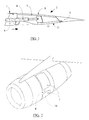
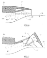
- Figure 1 of the accompanying drawings shows a known example of realization of a thrust reverser of this type, applied as shown in the partial schematic perspective view of Figure 2, to a turbofan engine.
- the reversing device consists of doors 7 forming a movable part 2 and constituting in the inactive position, during direct jet operation, part of the enclosure exterior, and of a fixed structure carrying out this rollover outside upstream of the doors, through an upstream part 1 downstream doors by a downstream part 3 and between doors 7 by through beams 18 which connect the downstream part 3 of the outer casing at the upstream part 4 of the outer casing.
- the doors 7 are mounted on a circumference of the cowling outside and are pivotally mounted in an area intermediate of their side walls on the beams 18 located on either side of these doors, these walls side constituting with the upstream and downstream walls, the walls which connect the outer part 9 of the doors 7, which constitute a part of the external wall of the nacelle, to the interior part 11 of the doors 7, which constitute a part of the outer wall of the duct.
- the upstream part 1 of fixed structure includes a front frame 6 which serves as a support for the movement control means doors 7, constituted for example by jacks 8.
- the doors 7 tilt in such a way that the part of the doors located downstream of the pivots comes to more or less completely obstruct the duct, and in such a way that the upstream part of the doors comes to clear a passage in the outer casing of so as to allow the secondary flow to be channeled radially with respect to the axis of the conduit.
- the upstream part of the doors 7 protrudes outside the outer cowling for reasons of dimensioning the passage which must be capable of allowing this flow to pass without compromising the operation of the engine.
- the pivot angle of the doors is adjusted so as to allow the flow to pass and so as to suppress the thrust of this flow, or even begin to generate a counter-thrust by generating a component of the flow deflected upstream.
- the nacelle 14 includes a thrust reverser 16 whose mobile part is constituted in the example represented by four displaceable elements (it can be one, two, three, four or even more than four ) or shells 17.
- the outer surface 18 of each shell 17 constitutes a part of the outer surface 19 of the nacelle 14 and is in its extension.
- An upstream part 21 of the shell 17 externally covers a downstream part 22 of said fixed structure 20 of the nacelle.
- the downstream trimming 15 of the shell 17 forms a part of the ejection section of the nozzle of the secondary channel.
- a downstream part 23 of the shell 17 is arranged in the downstream extension of the fixed structure 20 of the nacelle.
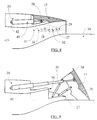
- FIG. 3 represents an embodiment of the invention constituted by upstream 36 and downstream 27 connecting rods connected downstream from the side walls of the fixed structure 20 (or beams 52) by a joint 32 and 29 respectively and fixed d 'an articulated manner at points 31 and 28 on the side walls of the shells 17.
- the upstream 36 and downstream 27 connecting rods are included in the thickness of the beam 52 between the wall of the external vein of the annular channel 15 and the external surface 19 of the fixed structure 20 of the nacelle.
- Figure 5 shows in perspective this mode of the invention in reverse jet position.
- a lateral jack 40 is fixed to the fixed structure 20 at a pivot point 42 located at the end or at any point along the length of the body of the jack.
- the cylinder can be simple, telescopic, hydraulic, electric or pneumatic.
- the point 41 for attaching said cylinder to the upstream connecting rod 36 is positioned at any point defined by those skilled in the art according to the need between the two pivots 31 and 32 of the upstream connecting rod 36.
- One or two cylinders can be used by shell assembly 17. It should be noted that the drive can also be done by the downstream rod 27 under the same conditions as explained above.
- the jack 40 can also be placed in the beam 52.
- a single jack can drive two shells.
- Figure 4 shows the cylinder 40 driving the upstream link 36. It pivots around its point of articulation 32.
- Said upstream link 36 takes the shell 17 downstream.
- the operation and the angle of the shell 17 are provided, in each operating phase and in the reverse jet position, by the downstream connecting rod 27.
- the tilting of the shell 17 is achieved by the angular differential existing between the two connecting rods, between the direct jet phase and that of the reverse jet.
- the opening distance downstream of the nacelle, the angle and the position of the shell 17 are defined to respond to the aerodynamic effect sought. They are a function of the fixed pivot points 32 and 29 retained on the beam 52, of the length of the upstream 36 and downstream 27 connecting rods and of the hooking positions of said connecting rods on the shell 17 at points 31 and 28.
- the deflection edge 56 can be of shape and clipping adapted to the aerodynamic requirements in direct jet and especially reverse jet mode.
- the internal part 57 of the shell 17 being adjusted with the defined shape of said deflection edge 56.
- a seal 50 can be placed downstream of the downstream part 22 of the fixed structure 20 to minimize the impact of the effort applied to the inside of the shell 17 by the flux circulating in the annular canal 15.
- Locking in the direct jet position of the shells 17 can take place either on the upstream 36 and / or downstream 27 connecting rods, or on part of the internal wall of the shell 17 in covering of the downstream part 22 of the fixed structure 20 of the nacelle, or on the upstream part of the shell 17 of a fashion known per se.
- the shell 17 can rest on its downstream part 15 in abutment on the structure 30, or the jack can limit the stroke of said shell 17.
- FIGS 6 and 7 show a drive by cylinder 40 telescopic but the cylinder depending on the space left upstream the basket can be simple. This can be connected to the upstream connecting rod 36 at the point of attachment 31 thereof with the shell 17 but also at an intermediate point between the pivot points 31 and 32 of said upstream connecting rod. Likewise said cylinder 40 can drive the shell 17 by through the connecting rod 27 under the same conditions as those of the upstream connecting rod 36.
- Figures 8 and 9 show a shell drive 17 by telescopic cylinder 40, the cylinder according to the space left at the upstream of the nacelle being able to be simple, in the central axis of the shell 17.
- the hooking 58 of the jack rod on the inner part of shell 17 is located in an area between upstream and middle of the inner shell 17.
- FIGS. 10 and 11 show a kinematics produced by a drive of the upstream connecting rod 36 placed in the central part of the shell 17.
- the upstream connecting rod 36 is hooked at a pivot point 32 on the downstream part 22 of the fixed structure 20 or, as shown in the figures, on a projection 51 of the downstream part 22 of the fixed structure 20 of the nacelle. It may be a single connecting rod 36 or more, located in the axis of the shell 17 or offset from the axis, between the longitudinal middle of the shell 17 and its lateral ends.
- the attachment point 31 of the upstream connecting rod 36 on the shell is located in an area in the vicinity of the upstream of the shell.
- the drive by cylinder is carried out under the same conditions as those already explained in Figures 3 to 9.
- a drive system which can be by cam or any other known to those skilled in the art, can make the point (s) 32 of the connecting rod 36 or the point (s) 29 of the connecting rod 27 movable, thus making it possible to bring out the downstream part of the shell.
- This system makes it possible to have a variable nozzle associated with the shells of the inverter.
- Figure 12 shows the shells 17 in reverse jet position in one embodiment of the invention.
- Downstream clipping 15 of the shells 17 can receive a shape marrying the external structure of the engine compartment 30, this so to optimize leaks in reverse jet mode between said shells and the structure surrounding the engine compartment.
- the shells 17 may have corners cut such as 34 and 35 to allow better adjustment shell leaks and adapt the flow rate reversed, in particular the ratio of the counter-thrust to the residual thrust.
- Figures 13 and 14 show another embodiment of the invention where the shell 37 completely covers the outside of the downstream 38 of the fixed structure 20 of the nacelle 14.
- the inner surface 25 of the downstream 38 is terminated on the downstream side by a fixed part in extension 38a.
- the part 38a delimits on the one hand, on the external side, the external surface of the nacelle, in the direct jet extension, of the external surface 18 of the shell 37, and on the other hand, on the internal side, the external surface of the downstream part of the channel 15 of the secondary flow 16.
- the end 43 of the part 38a thus constitutes in direct jet a trailing edge and during operation in reverse thrust, as shown in FIG. 14, a deflection edge delimiting one edge of the reversing well created by the shell 37.
- the system for controlling the movements and locking the shells 37 can be kept identical to those which have been described in the embodiments shown in FIGS. 3 to 11.
- the downstream trimming 53 of the shells 37 can receive a shape adapted according to the desired effect in reverse jet mode to obtain the desired clearance between the external structure of the engine compartment 30 and the shells 37, this without affecting the end 43 of the trailing edge of the gondola.
- FIGS. 15 and 16 show a variant of the embodiment of the invention shown in FIGS. 13 and 14.
- one (or even several) opening 54 can be made in the downstream part 38 of the fixed structure 20 of the nacelle. This (or these) opening 54 is blocked in direct jet mode by a part 55 of the internal of the shell 37. The surface of said part 55 of the shell is connected to the internal surface 25 and 25a of the downstream part 38 of the fixed structure 20 of the nacelle.
- These openings 54 are in number, length, width and clipping suitable for allowing the desired performance in jet inversion mode.
Landscapes
- Engineering & Computer Science (AREA)
- Chemical & Material Sciences (AREA)
- Combustion & Propulsion (AREA)
- Mechanical Engineering (AREA)
- General Engineering & Computer Science (AREA)
- Structures Of Non-Positive Displacement Pumps (AREA)
- Turbine Rotor Nozzle Sealing (AREA)
- Control Of Turbines (AREA)
Description
La présente invention concerne un dispositif d'inversion de poussée de turboréacteur à double flux. Le turboréacteur est équipé d'un conduit en arrière de la soufflante dont le but est de canaliser le flux secondaire dit froid, ce conduit est constitué d'une paroi interne qui entoure la structure du moteur proprement dite en arrière de la soufflante, et d'une paroi externe dont la partie amont vient en continuité du carter moteur qui entoure la soufflante. Cette paroi externe peut canaliser à la fois le flux secondaire et le flux primaire dans sa partie aval, et ceci en arrière de l'éjection du flux primaire, dit chaud, dans le cas de nacelle à flux mélangés ou à flux confluents par exemple, mais dans d'autres cas, la paroi externe ne canalise que le flux secondaire, dans le cas de nacelles dites à flux séparés.The present invention relates to a device for reversing thrust of turbofan. The turbojet is fitted with a duct behind the blower, the purpose of which is to channel the secondary flow known as cold, this conduit is consisting of an internal wall which surrounds the structure of the motor itself behind the blower, and a external wall whose upstream part comes in continuity with the crankcase that surrounds the blower. This outer wall can channel both the secondary flow and the flow primary in its downstream part, and this behind the ejection of the primary flow, called hot, in the case of nacelle with mixed flows or confluent flows for example, but in other cases, the outer wall only channels the secondary flow, in the case of nacelles called flow separated.
Une paroi peut également caréner l'extérieur du moteur, c'est à dire l'extérieur du carter qui entoure la soufflante et l'extérieur de la paroi extérieure du conduit décrit ci-dessus, ceci dans le but de minimiser la traínée de l'ensemble propulsif. Ceci est notamment le cas pour des ensembles propulsifs rapportés sur l'extérieur d'aéronef, particulièrement lorsque ces ensembles propulsifs sont attachés sous les ailes ou à l'arrière du fuselage.A wall can also cover the outside of the engine, this is to say the outside of the casing that surrounds the blower and the exterior of the exterior wall of the conduit described above, this in order to minimize the drag of the propulsion unit. This is particularly the case for propulsion systems added to the exterior of the aircraft, particularly when these propulsion systems are attached under the wings or at the rear of the fuselage.
Nous appellerons capotage extérieur l'ensemble constitué par la paroi extérieure de la nacelle.We will call the outer casing the assembly constituted by the outer wall of the nacelle.
La figure 1 des dessins joints montre un exemple connu de réalisation d'un inverseur de poussée de ce type, appliqué comme le montre la vue schématique partielle en perspective de la figure 2, à un turboréacteur à double flux.Figure 1 of the accompanying drawings shows a known example of realization of a thrust reverser of this type, applied as shown in the partial schematic perspective view of Figure 2, to a turbofan engine.
Le dispositif d'inversion est constitué de portes 7 formant
une partie mobile 2 et constituant en position inactive, lors
d'un fonctionnement en jet direct, une partie du capotage
extérieur, et d'une structure fixe réalisant ce capotage
extérieur en amont des portes, par une partie amont 1 en aval
des portes par une partie aval 3 et entre les portes 7 par
l'intermédiaire de poutres 18 qui relient la partie aval 3 du
capotage extérieur à la partie amont 4 du capotage extérieur.
Les portes 7 sont montées sur une circonférence du capotage
extérieur et sont montées pivotantes dans une zone
intermédiaire de leurs parois latérales sur les poutres 18
situées de part et d'autre de ces portes, ces parois
latérales constituant avec les parois amont et aval, les
parois qui relient la partie extérieure 9 des portes 7, qui
constituent une partie de la paroi extérieure de la nacelle,
à la partie intérieure 11 des portes 7, qui constituent une
partie de la paroi extérieure du conduit.The reversing device consists of
La partie amont 1 de structure fixe comporte un cadre avant 6
qui sert de support aux moyens de commande des déplacements
des portes 7, constitués par exemple par des vérins 8.The
En position activée, les portes 7 basculent de telle façon
que la partie des portes situées en aval des pivots, vient
obstruer plus ou moins totalement le conduit, et de telle
façon que la partie amont des portes vient dégager un passage
dans le capotage extérieur de manière à permettre au flux
secondaire d'être canalisé radialement par rapport à l'axe du
conduit. La partie amont des portes 7 fait saillie à
l'extérieur du capotage extérieur pour des raisons de
dimensionnement du passage qui doit être capable de laisser
passer ce flux sans compromettre le fonctionnement du moteur.
L'angle de pivotement des portes est ajusté de manière à
permettre le passage du flux et de manière à supprimer la
poussée de ce flux, voire à commencer à générer une contre
poussée en générant une composante du flux dévié vers
l'amont.
Des exemples de réalisation de ce type d'inverseur de poussée
de turboréacteur à portes basculantes sont décrits notamment
par FR-A-2 618 853, FR-A 2.618.852, FR-A- 2 621 082, FR-A 2
627 807, FR-A 2 634 251, FR-A 2 638 207 et FR-A 2 651 021
dont est titulaire la demanderesse. In the activated position, the
Examples of embodiment of this type of thrust reverser of a turbojet engine with tilting doors are described in particular by FR-A-2 618 853, FR-A 2.618.852, FR-A- 2 621 082, FR-A 2 627 807 , FR-A 2 634 251, FR-A 2 638 207 and FR-A 2 651 021 owned by the plaintiff.
Dans certaines applications, l'installation d'un inverseur de
poussée de ce type connu soulève de grandes difficultés et
peut conduire pratiquement à une impossibilité. C'est
notamment le cas pour des turboréacteurs à très grand taux de
dilution, associés lors du montage sur l'avion à une nacelle
très courte et à un canal de flux secondaire court
correspondant à un fonctionnement dit à flux séparés, pour
lesquels l'utilisation de portes proprement dites comme
obstacles d'inversion est mal adaptée.
On connaít par FR-A- 2.722.534 un inverseur de poussée adapté
à ces applications particulières et dans lequel au moins une
partie amont de chaque obstacle ou coquille de l'inverseur,
lors du fonctionnement en jet direct, recouvre une partie
interne d'une structure fixe constituant la paroi extérieure
du canal du flux secondaire de manière que la surface
extérieure de ladite coquille constitue une partie de la
surface extérieure de la nacelle dans le prolongement de la
surface extérieure de ladite structure fixe, chaque coquille
étant associée à au moins une bielle amont et à au moins une
bielle aval, lesdites bielles assurant la fixation et le
maintien de la coquille ainsi que son guidage lors des
déplacements de coquille. Pour certaines applications, chaque
coquille comporte une partie aval dont la surface intérieure
est dans le prolongement de la surface extérieure du canal en
jet direct.
Cette solution connue comporte toutefois certains
inconvénients. En effet, la bielle en aval de la coquille se
situe dans une zone d'accélération du flux dans le canal
annulaire et notamment dans la zone du pivot de bielle sur le
capot primaire, la vitesse du flux avoisine ou dépasse la
vitesse du son en vol de croisière, ce qui entraíne de fortes
pertes aérodynamiques. En outre, d'autres pertes
aérodynamiques sont occasionnées par une entaille ou
empreinte ménagée dans la structure aval de la coquille ou de
la structure fixe pour permettre le débattement de la bielle
aval. Enfin, du fait que le bord aval de la coquille forme
l'extrémité aval de la nacelle et se termine en structure
fine, des butées doivent être disposées sur la structure afin
de retenir la coquille en jet inversé par contact sur le
capot primaire. Par suite, ces butées débordent les lignes de
la nacelle et créent des pertes aérodynamiques.
Un inverseur de poussée de turboréacteur permettant de
répondre à ces conditions sans encourir les inconvénients des
solutions précédemment connues est caractérisé en ce que les
coquilles sont entraínées par au moins une bielle amont et au
moins une bielle aval, lesdites bielles étant reliées de
manière articulée aux parois latérales des coquilles, étant
en outre installées sur la structure fixe de la nacelle et
disposées en jet direct dans l'épaisseur de la poutre fixe
séparant deux coquilles de manière que le débattement des
bielles ne crée pas d'entaille apparente dans la structure
fixe en jet direct.
D'autres caractéristiques et avantages de l'invention seront
mieux compris à la lecture de la description qui va suivre
d'un mode de réalisation de l'invention en référence aux
dessins annexés sur lesquels :
- la figure 1 représente une demi-vue schématique, en coupe longitudinale par un plan passant par l'axe de rotation d'un turboréacteur, d'un inverseur de poussée à portes pivotantes, en position fermé, d'un type connu et qui a fait précédemment l'objet d'une description ;
- la figure 2 représente une vue schématique en perspective d'un inverseur de poussée du type précité montré en position monté et avec les portes fermées ;
- la figure 3 représente, dans une vue analogue à celle de la figure 1, un inverseur de poussée selon un mode de réalisation de l'invention en position jet direct ;
- la figure 4 représente le mode de réalisation décrite dans la figure 3 en position jet inversé ;
- la figure 5 représente le mode de réalisation de l'invention en mode jet inversé décrit dans la figure 4 en perspective vue de l'avant ;
- les figures 6 et 7 représentent un mode d'entraínement par vérin sur un pivot de bielle en position jet direct et jet inversé ;
- les figures 8 et 9 représentent un mode d'entraínement de la coquille par vérin central en position jet direct et jet inversé ;
- les figures 10 et 11 représentent un mode de l'invention par manoeuvre de bielle amont centrale en position jet direct et jet inversé ;
- la figure 12 représente en vue de l'arrière, la perspective d'un mode de l'invention montrant les découpes aval de la coquille possibles à réaliser ;
- les figures 13 et 14 représentent dans un mode de réalisation de l'invention, la coquille recouvrant entièrement la structure interne de la nacelle en position jet direct et jet inversé ;
- les figures 15 et 16 représentent dans un mode défini suivant les figures 13 et 14, un ajout d'ouverture dans la structure fixe de la nacelle en position jet direct et jet inversé.
We know from FR-A-2,722,534 a thrust reverser suitable for these particular applications and in which at least an upstream part of each obstacle or shell of the reverser, during direct jet operation, covers an internal part of a fixed structure constituting the external wall of the secondary flow channel so that the external surface of said shell constitutes a part of the external surface of the nacelle in line with the external surface of said fixed structure, each shell being associated with at least an upstream connecting rod and at least one downstream connecting rod, said connecting rods securing and maintaining the shell as well as guiding it during shell displacements. For certain applications, each shell has a downstream part, the internal surface of which is in line with the external surface of the channel in direct jet.
This known solution however has certain drawbacks. Indeed, the connecting rod downstream of the shell is located in a zone of acceleration of the flow in the annular channel and in particular in the zone of the connecting rod pivot on the primary cover, the speed of the flow approaches or exceeds the speed of sound in cruise flight, which results in high aerodynamic losses. In addition, other aerodynamic losses are caused by a notch or imprint made in the downstream structure of the shell or of the fixed structure to allow the movement of the downstream connecting rod. Finally, because the downstream edge of the shell forms the downstream end of the nacelle and ends in a fine structure, stops must be arranged on the structure in order to retain the shell in reverse jet by contact on the primary cover. As a result, these stops extend beyond the lines of the nacelle and create aerodynamic losses.
A turbojet thrust reverser making it possible to meet these conditions without incurring the drawbacks of the previously known solutions is characterized in that the shells are driven by at least one upstream connecting rod and at least one downstream connecting rod, said connecting rods being hingedly connected to the side walls of the shells, being also installed on the fixed structure of the nacelle and arranged in a direct jet in the thickness of the fixed beam separating two shells so that the movement of the connecting rods does not create an apparent notch in the fixed structure in direct jet.
Other characteristics and advantages of the invention will be better understood on reading the following description of an embodiment of the invention with reference to the appended drawings in which:
- FIG. 1 represents a schematic half-view, in longitudinal section through a plane passing through the axis of rotation of a turbojet engine, of a thrust reverser with pivoting doors, in the closed position, of a known type and which has previously described;
- 2 shows a schematic perspective view of a thrust reverser of the aforementioned type shown in the mounted position and with the doors closed;
- FIG. 3 represents, in a view similar to that of FIG. 1, a thrust reverser according to an embodiment of the invention in the direct jet position;
- FIG. 4 represents the embodiment described in FIG. 3 in the reverse jet position;
- FIG. 5 represents the embodiment of the invention in reverse jet mode described in FIG. 4 in perspective seen from the front;
- Figures 6 and 7 show a cylinder drive mode on a connecting rod pivot in the direct jet and reverse jet position;
- Figures 8 and 9 show a mode of driving the shell by central cylinder in direct jet and reverse jet position;
- Figures 10 and 11 show a mode of the invention by maneuvering a central upstream connecting rod in the direct jet and reverse jet position;
- FIG. 12 shows, in rear view, the perspective of a mode of the invention showing the possible downstream cuts of the shell to be made;
- Figures 13 and 14 show in one embodiment of the invention, the shell entirely covering the internal structure of the nacelle in the direct jet and reverse jet position;
- Figures 15 and 16 show in a mode defined according to Figures 13 and 14, an addition of opening in the fixed structure of the nacelle in direct jet and reverse jet position.
Selon un mode de réalisation représenté sur la figure 3, la
nacelle 14 comporte un inverseur de poussée 16 dont la partie
mobile est constituée dans l'exemple représenté par quatre
éléments déplaçables (ce peut être un, deux, trois, quatre
voire plus de quatre) ou coquilles 17. La surface extérieure
18 de chaque coquille 17 constitue une partie de la surface
extérieure 19 de la nacelle 14 et se trouve dans son
prolongement. Une partie amont 21 de la coquille 17 recouvre
extérieurement une partie aval 22 de ladite structure fixe 20
de la nacelle. Le détourage aval 15 de la coquille 17 forme
une partie de la section d'éjection de la tuyère du canal
secondaire. Une partie aval 23 de la coquille 17 est disposée
dans le prolongement vers l'aval de la structure fixe 20 de
la nacelle. Amont et aval sont définis par rapport au sens
normal de circulation des gaz dans le turboréacteur, en
fonctionnement de jet direct. La surface intérieure 24 de
ladite partie aval 23 de la coquille 17 se raccorde à la
surface intérieure 25 de ladite partie aval 22 de la
structure fixe 20 de la nacelle, délimitant ainsi
extérieurement le canal secondaire 15 de circulation du flux
froid secondaire, symbolisé par la flèche 26.
La figure 3 représente un mode de réalisation de l'invention
constitué par des bielles amont 36 et aval 27 reliées vers
l'aval des parois latérales de la structure fixe 20 (ou des
poutres 52) par une articulation respectivement 32 et 29 et
fixées d'une manière articulée aux points 31 et 28 sur les
parois latérales des coquilles 17.
En position jet direct les bielles amont 36 et aval 27 sont
comprises dans l'épaisseur de la poutre 52 entre la paroi de
la veine externe du canal annulaire 15 et la surface
extérieure 19 de la structure fixe 20 de la nacelle. La
figure 5 montre en perspective ce mode de l'invention en
position jet inversé.According to an embodiment shown in FIG. 3, the
FIG. 3 represents an embodiment of the invention constituted by upstream 36 and downstream 27 connecting rods connected downstream from the side walls of the fixed structure 20 (or beams 52) by a
In the direct jet position, the upstream 36 and downstream 27 connecting rods are included in the thickness of the
Un vérin latéral 40 est fixé sur la structure fixe 20 en un
point pivot 42 situé en extrémité ou en un point quelconque
sur la longueur du corps du vérin. Le vérin peut être simple,
télescopique, hydraulique, électrique ou pneumatique.
Le point 41 d'accrochage dudit vérin sur la bielle amont 36
est positionné en un point quelconque défini par l'homme de
l'art suivant la nécessité entre les deux pivots 31 et 32 de
la bielle amont 36. Un ou deux vérins peuvent être utilisés
par ensemble de coquille 17. Il est à noter que
l'entraínement peut aussi se faire par la bielle aval 27 dans
les mêmes conditions qu'expliquées précédemment.
Le vérin 40 peut être aussi placé dans la poutre 52. Un seul
vérin peut entraíner deux coquilles.
La figure 4 représente le vérin 40 entraínant la bielle amont
36. Elle pivote autour de son point d'articulation 32. Ladite
bielle amont 36 emmène en basculement vers l'aval la coquille
17. La manoeuvre et l'angle de la coquille 17 sont assurés,
dans chaque phase de manoeuvre et en position jet inversé,
par la bielle aval 27. Le basculement de la coquille 17 est
réalisé par le différentiel angulaire existant entre les deux
bielles, entre la phase de jet direct et celle de jet
inversé. A
The
The
Figure 4 shows the
La distance d'ouverture vers l'aval de la nacelle, l'angle et
la position de la coquille 17 sont définis pour répondre à
l'effet aérodynamique recherché. Ils sont fonction des points
pivots fixes 32 et 29 retenus sur la poutre 52, de la
longueur des bielles amont 36 et aval 27 et des positions
d'accrochage desdites bielles sur la coquille 17 aux points
31 et 28.
Le bord de déviation 56 peut être de forme et de détourage
adapté aux exigences aérodynamiques en mode jet direct et
surtout jet inversé. La partie 57 interne de la coquille 17
étant ajustée avec la forme définie dudit bord de déviation
56.The opening distance downstream of the nacelle, the angle and the position of the
The
Un joint 50 peut être placé en aval de la partie aval 22 de
la structure fixe 20 pour minimiser l'impact de l'effort
appliqué sur l'interne de la coquille 17 par le flux
circulant dans le canal annulaire 15.A
Le verrouillage en position jet direct des coquilles 17 peut
s'effectuer soit sur les bielles amont 36 et/ou aval 27, soit
sur une partie de la paroi interne de la coquille 17 en
recouvrement de la partie aval 22 de la structure fixe 20 de
la nacelle, soit sur la partie amont de la coquille 17 d'un
mode connu en soi.Locking in the direct jet position of the
En phase finale d'inversion du jet, la coquille 17 peut
reposer sur sa partie aval 15 en butée sur la structure 30,
ou bien le vérin peut limiter la course de ladite coquille
17.In the final jet inversion phase, the
Les figures 6 et 7 montrent un entraínement par vérin 40
télescopique mais le vérin selon la place laissée à l'amont
de la nacelle peut être simple. Celui-ci peut être relié à la
bielle amont 36 au point d'accrochage 31 de celle-ci avec la
coquille 17 mais aussi bien en un point intermédiaire entre
les points pivots 31 et 32 de ladite bielle amont. De même
ledit vérin 40 peut entraíner la coquille 17 par
l'intermédiaire de la bielle 27 dans les mêmes conditions que
celles de la bielle amont 36. Figures 6 and 7 show a drive by
Les figures 8 et 9 montrent un entraínement de coquille 17
par vérin 40 télescopique, le vérin selon la place laissée à
l'amont de la nacelle pouvant être simple, dans l'axe central
de la coquille 17. L'accrochage 58 de la tige de vérin sur
l'interne de la coquille 17 se situe dans une zone entre
l'amont et le milieu de l'interne de la coquille 17.Figures 8 and 9 show a
Les figures 10 et 11 montrent une cinématique réalisée par un
entraínement de la bielle amont 36 placée dans la partie
centrale de la coquille 17. La bielle amont 36 est accrochée
en un point pivot 32 sur la partie aval 22 de la structure
fixe 20 ou, comme représenté sur les figures, sur une
excroissance 51 de la partie aval 22 de la structure fixe 20
de la nacelle.
Ce peut être une seule bielle 36 ou plusieurs, situées dans
l'axe de la coquille 17 ou décalées de l'axe, entre le milieu
longitudinal de la coquille 17 et ses extrémités latérales.
Le point d'accrochage 31 de la bielle amont 36 sur la
coquille se situe dans une zone au voisinage de l'amont de la
coquille. L'entraínement par vérin s'effectue dans les mêmes
conditions que celles déja expliquées dans les figures 3 à 9.
Selon l'emplacement retenu pour le point d'accrochage 32 de
la bielle 36, dans une direction le plus en aval possible par
rapport à la surface aval interne 24 de la coquille 17,
celle-ci peut être rendue auto fermante.
La coquille 17 étant maintenue en partie amont, par exemple
par un ou des verrous la rendant en partie pivotante à cette
extrémité, un système d'entraínement, qui peut être par came
ou tout autre connu de l'homme de métier, peut rendre le(s)
point(s) 32 de la bielle 36 ou le(s) point(s) 29 de la bielle
27 mobile(s), permettant ainsi de faire ressortir la partie
aval de la coquille. Ce système permet d'avoir une tuyère
variable associée aux coquilles de l'inverseur.FIGS. 10 and 11 show a kinematics produced by a drive of the upstream connecting
It may be a single connecting
The
The
or any other known to those skilled in the art, can make the point (s) 32 of the connecting
La figure 12 montre les coquilles 17 en position jet inversé
dans un mode de réalisation de l'invention. Le détourage aval
15 des coquilles 17 peut recevoir une forme épousant la
structure externe du compartiment moteur 30, ceci afin
d'optimiser les fuites en mode jet inversé entre lesdites
coquilles et la structure entourant le compartiment moteur.
De même que les coquilles 17 peuvent comporter des coins
coupés tels que 34 et 35 afin de permettre de mieux régler
les fuites de coquilles et d'adapter le débit du flux
inversé, notamment le rapport de la contre poussée à la
poussée résiduelle.Figure 12 shows the
Les figures 13 et 14 montrent un autre mode de réalisation de
l'invention où la coquille 37 vient recouvrir en totalité
l'extérieur de l'aval 38 de la structure fixe 20 de la
nacelle 14. La surface intérieure 25 de l'aval 38 est
terminée du côté aval par une partie fixe en prolongement
38a. La partie 38a délimite d'une part, du côté externe, la
surface extérieure de nacelle, dans le prolongement en jet
direct, de la surface extérieure 18 de la coquille 37, et
d'autre part, du côté interne, la surface extérieure de la
partie aval du canal 15 du flux secondaire 16. L'extrémité 43
de la partie 38a constitue ainsi en jet direct un bord de
fuite et lors du fonctionnement en inversion de poussée, tel
que représenté sur la figure 14, un bord de déviation
délimitant un bord du puits d'inversion créé par la coquille
37. Le système de commande des déplacements et de
verrouillage des coquilles 37 peuvent être conservés
identiques à ceux qui ont été décrits dans les modes de
réalisation représentés sur les figures 3 à 11.
Le détourage aval 53 des coquilles 37 peuvent recevoir une
forme adaptée suivant l'effet recherché en mode jet inversé
pour obtenir le jeu voulu entre la structure extérieure du
compartiment moteur 30 et les coquilles 37, ceci sans
affecter l'extrémité 43 du bord de fuite de la nacelle.Figures 13 and 14 show another embodiment of the invention where the
The downstream trimming 53 of the
Les figures 15 et 16 montrent une variante au mode de
réalisation de l'invention représenté sur les figures 13 et
14. Pour des raisons d'augmentation du passage du flux ou de
pilotage de nappes en mode jet inversé, une (voire plusieurs)
ouverture 54 peut être pratiquée dans la partie aval 38 de la
structure fixe 20 de la nacelle. Cette (ou ces) ouverture 54
est bouchée en mode jet direct par une partie 55 de l'interne
de la coquille 37. La surface de ladite partie 55 de la
coquille se raccorde à la surface intérieure 25 et 25a de la
partie aval 38 de la structure fixe 20 de la nacelle.
Ces ouvertures 54 sont en nombre, en longueur, en largeur et
en détourage appropriés pour permettre les performances
désirées en mode d'inversion de jet.FIGS. 15 and 16 show a variant of the embodiment of the invention shown in FIGS. 13 and 14. For reasons of increasing the passage of the flow or of controlling sheets in reverse jet mode, one (or even several) opening 54 can be made in the
These
Claims (8)
- A bypass turbojet engine thrust reverser comprising displaceable elements or shells (17; 37) adapted, when in the closed position, to be integrated into the outer wall of the annular secondary flow duct, and, when in the deployed position, to form obstacles deflecting the secondary flow to produce a thrust reversal, said shells (17; 37) being associated with displacement means such as rams, at least an upstream (part 21) of each shell(17)of the reverser (16) overlapping, in forward thrust operation, an internal part (22) of a fixed structure (20) forming the outer wall of the secondary flow duct (15) so that an external surface (18)of said shell (17)forms a part of the external nacelle surface which lies flush with the external surface (19)of said fixed structure (20), characterised in that the shells (17; 37) are driven by at least one upstream rod (36) and at least one downstream rod (27), said rods (36, 27) being articulated to the side walls of the shells, being installed on the fixed structure of the nacelle, and being disposed, in forward thrust operation, in the thickness of a fixed beam separating two shells (17; 37) so that the movement of the rods does not disclose any visible recess in the fixed structure in forward thrust operation.
- A bypass turbojet engine thrust reverser according to claim 1 wherein said rods (27, 36) are driven by at least one ram which is connected to one of the rods and is disposed in the thickness of the nacelle structure in forward thrust operation.
- A bypass turbojet engine thrust reverser according to claim 2 wherein the point of connection between the ram and the rod is disposed at an intermediate point between the articulation points of the rod.
- A bypass turbojet engine thrust reverser according to claim 2 wherein the point of connection between the ram and the rod is disposed at the point of articulation of the rod to the shell.
- A bypass turbojet engine thrust reverser according to claim 1 wherein 5he shell-driving ram is disposed on the longitudinal axis of the shell and is directly connected thereto.
- A bypass turbojet engine thrust reverser according to claim 1 wherein an upstream rod(36) disposed in the central part of the shell (17) is articulated on a pivot (32) disposed on the downstream part (22) of the fixed structure (20).
- A bypass turbojet engine thrust reverser according to any of claims 1 to 6 wherein the internal part (38) of the fixed structure, overlapped in forward thrust operation by the whole of said shell (37), is prolonged by a fixed downstream part (38a) bounding, on the one hand, on the external side, the external nacelle surface which lies flush with the external surface of the shell in forward thrust operation and, on the other hand, on the internal side, the external surface of the downstream part of the secondary flow duct (15) in all operational configurations, so as to form a trailing edge in forward thrust operation and a deflecting edge (43)in reverse thrust operation which bounds a reversal sink.
- A bypass turbojet engine thrust reverser according to claim 7 wherein said downstream part (38a) of the fixed structure is formed with at least one aperture (54) which is closed, in forward thrust operation, by an internal part (55) of the shell (37).
Applications Claiming Priority (2)
| Application Number | Priority Date | Filing Date | Title |
|---|---|---|---|
| FR9616030 | 1996-12-26 | ||
| FR9616030A FR2757901B1 (en) | 1996-12-26 | 1996-12-26 | DOWNSTREAM DOUBLE FLOW TURBOREACTOR DRIVE INVERTER |
Publications (2)
| Publication Number | Publication Date |
|---|---|
| EP0851111A1 EP0851111A1 (en) | 1998-07-01 |
| EP0851111B1 true EP0851111B1 (en) | 2002-08-07 |
Family
ID=9499150
Family Applications (1)
| Application Number | Title | Priority Date | Filing Date |
|---|---|---|---|
| EP97403072A Expired - Lifetime EP0851111B1 (en) | 1996-12-26 | 1997-12-18 | Turbofan thrust reverser with aft end flaps |
Country Status (7)
| Country | Link |
|---|---|
| US (1) | US5974783A (en) |
| EP (1) | EP0851111B1 (en) |
| JP (1) | JPH10196456A (en) |
| CA (1) | CA2225608C (en) |
| DE (1) | DE69714565T2 (en) |
| FR (1) | FR2757901B1 (en) |
| WO (1) | WO1998029654A1 (en) |
Families Citing this family (29)
| Publication number | Priority date | Publication date | Assignee | Title |
|---|---|---|---|---|
| FR2887854B1 (en) | 2005-06-30 | 2008-08-08 | Airbus France Sas | PLATFORM FOR AN AIRCRAFT AND AN AIRCRAFT PROVIDED WITH AT LEAST ONE SUCH NACELLE |
| US8015797B2 (en) | 2006-09-21 | 2011-09-13 | Jean-Pierre Lair | Thrust reverser nozzle for a turbofan gas turbine engine |
| US8127529B2 (en) * | 2007-03-29 | 2012-03-06 | United Technologies Corporation | Variable area fan nozzle and thrust reverser |
| US7966808B2 (en) * | 2007-04-30 | 2011-06-28 | General Electric Company | Baffle seal for gas turbine engine thrust reverser |
| WO2008147260A1 (en) * | 2007-05-25 | 2008-12-04 | Volvo Aero Corporation | A device for moving a plurality of hatches in a gas turbine engine |
| US8006479B2 (en) * | 2007-10-15 | 2011-08-30 | United Technologies Corporation | Thrust reversing variable area nozzle |
| US8052086B2 (en) | 2007-11-16 | 2011-11-08 | The Nordam Group, Inc. | Thrust reverser door |
| US8051639B2 (en) | 2007-11-16 | 2011-11-08 | The Nordam Group, Inc. | Thrust reverser |
| US8091827B2 (en) | 2007-11-16 | 2012-01-10 | The Nordam Group, Inc. | Thrust reverser door |
| US8052085B2 (en) | 2007-11-16 | 2011-11-08 | The Nordam Group, Inc. | Thrust reverser for a turbofan gas turbine engine |
| US8172175B2 (en) | 2007-11-16 | 2012-05-08 | The Nordam Group, Inc. | Pivoting door thrust reverser for a turbofan gas turbine engine |
| US7735778B2 (en) | 2007-11-16 | 2010-06-15 | Pratt & Whitney Canada Corp. | Pivoting fairings for a thrust reverser |
| US8127532B2 (en) | 2008-11-26 | 2012-03-06 | The Boeing Company | Pivoting fan nozzle nacelle |
| US8959889B2 (en) | 2008-11-26 | 2015-02-24 | The Boeing Company | Method of varying a fan duct nozzle throat area of a gas turbine engine |
| FR2946696B1 (en) * | 2009-06-10 | 2012-04-20 | Aircelle Sa | PUSH REVERSING DEVICE |
| FR2955154B1 (en) | 2010-01-08 | 2012-01-06 | Airbus Operations Sas | THRUST INVERTER FOR TURBO AIRCRAFT WITH DOUBLE FLOW SEMI-BURIAL |
| DE102011008919A1 (en) * | 2011-01-19 | 2012-07-19 | Rolls-Royce Deutschland Ltd & Co Kg | Aircraft gas turbine thrust reverser |
| US10006405B2 (en) | 2012-11-30 | 2018-06-26 | General Electric Company | Thrust reverser system with translating-rotating blocker doors and method of operation |
| US9016040B2 (en) | 2012-11-30 | 2015-04-28 | General Electric Company | Thrust reverser system with translating-rotating cascade and method of operation |
| US9631578B2 (en) | 2013-02-22 | 2017-04-25 | United Technologies Corporation | Pivot thrust reverser surrounding inner surface of bypass duct |
| US9694912B2 (en) | 2013-02-22 | 2017-07-04 | United Technologies Corporation | ATR guide pins for sliding nacelle |
| WO2014197033A2 (en) * | 2013-03-15 | 2014-12-11 | United Technologies Corporation | Pivot door thrust reverser |
| CA2934112C (en) | 2013-12-23 | 2018-11-06 | General Electric Company | Aircraft with injection cooling system and injection cooling system |
| US10113508B2 (en) | 2014-11-21 | 2018-10-30 | General Electric Company | Gas turbine engine and method of assembling the same |
| US10465538B2 (en) * | 2014-11-21 | 2019-11-05 | General Electric Company | Gas turbine engine with reversible fan |
| FR3055313B1 (en) | 2016-08-30 | 2021-12-17 | Safran Nacelles | NACELLE FOR TURBOREACTOR OF AIRCRAFT, WITH HYBRID AIR INLET AND BLOWER HOOD |
| PL235797B1 (en) | 2018-02-21 | 2020-10-19 | Gen Electric | Bell-shaped nozzle unit for gas-turbine engines |
| EP3702603B1 (en) | 2019-02-28 | 2023-12-13 | Airbus Operations GmbH | Thrust reverser assembly for an engine nacelle of an aircraft |
| CN112963268B (en) * | 2021-03-15 | 2022-01-04 | 南京航空航天大学 | Throat offset pneumatic vectoring nozzle of small-hole jet flow |
Family Cites Families (23)
| Publication number | Priority date | Publication date | Assignee | Title |
|---|---|---|---|---|
| US3844482A (en) * | 1973-06-01 | 1974-10-29 | Boeing Co | Variable ramp exhaust nozzle and clamshell reverser |
| US3915415A (en) * | 1974-03-21 | 1975-10-28 | Rohr Industries Inc | Overwing thrust reverser |
| US4030687A (en) * | 1976-02-23 | 1977-06-21 | The Boeing Company | Articulated nozzle for upper surface blown aircraft |
| US4216926A (en) * | 1978-06-30 | 1980-08-12 | Rohr Industries, Inc. | Linkage system for a turbo fan engine thrust reverser |
| US4278220A (en) * | 1979-03-30 | 1981-07-14 | The United States Of America As Represented By The Administrator Of The National Aeronautics And Space Administration | Thrust reverser for a long duct fan engine |
| US4545199A (en) * | 1982-06-14 | 1985-10-08 | Rohr Industries, Inc. | Fan cascade reverser having dual blocker doors |
| US4698964A (en) * | 1985-09-06 | 1987-10-13 | The Boeing Company | Automatic deflector for a jet engine bleed air exhaust system |
| FR2618853B1 (en) * | 1987-07-29 | 1989-11-10 | Hispano Suiza Sa | TURBOREACTOR DRIVE INVERTER WITH MOBILE DOOR DEFLECTOR |
| FR2618852B1 (en) * | 1987-07-29 | 1989-11-10 | Hispano Suiza Sa | TURBOREACTOR DRIVE INVERTER PROVIDED WITH A FLOW RECTIFIER DEVICE |
| FR2648869B1 (en) * | 1987-09-30 | 1994-09-30 | Hispano Suiza Sa | TURBOREACTOR DRIVE INVERTER WITH DOORS WITH VEIN PROFILE |
| FR2621082A1 (en) * | 1987-09-30 | 1989-03-31 | Hispano Suiza Sa | PUSH INVERTER OF TURBOJET WITH DOORS PROVIDED WITH A VEIN PROFILE PLATE |
| FR2622928A1 (en) * | 1987-11-05 | 1989-05-12 | Hispano Suiza Sa | PUSH INVERTER OF DOOR TURBOJET, WITH VARIABLE EJECTION SECTION |
| FR2627807B1 (en) * | 1988-02-25 | 1990-06-29 | Hispano Suiza Sa | DOUBLE-FLOW TURBOREACTOR DRIVE INVERTER HAVING DEVIATION EDGES WITH MOVABLE LIPS |
| FR2634251B1 (en) * | 1988-07-18 | 1993-08-13 | Hispano Suiza Sa | DOUBLE-FLOW TURBOREACTOR DRIVE INVERTER HAVING MOBILE DEVIATION EDGES |
| FR2638207B1 (en) * | 1988-10-20 | 1990-11-30 | Hispano Suiza Sa | TURBOJET DRIVE INVERTER WITH BALANCED PIVOTING DOORS |
| FR2650861A1 (en) * | 1989-08-08 | 1991-02-15 | Snecma | Bypass turbo jet thrust reverser with obstacles connected to the primary cowling |
| US5039171A (en) * | 1989-08-18 | 1991-08-13 | Societe Anonyme Dite Hispano-Suiza | Multi-panel thrust reverser door |
| FR2651021B1 (en) | 1989-08-18 | 1994-05-06 | Hispano Suiza Sa | TURBOREACTOR DRIVE INVERTER, WITH DOORS ASSOCIATED WITH AN UPSTREAM PANEL |
| FR2651278B1 (en) * | 1989-08-23 | 1994-05-06 | Hispano Suiza | INVERTER WITH GRIDS WITHOUT SLIDING COVER FOR TURBOREACTOR. |
| DE4039810C1 (en) * | 1990-12-13 | 1991-10-17 | Mtu Muenchen Gmbh | |
| FR2722534B1 (en) * | 1994-07-13 | 1996-08-14 | Hispano Suiza Sa | DOUBLE FLOW TURBOREACTOR DRIVE INVERTER WITH EXTERNAL OBSTACLES |
| FR2737256B1 (en) * | 1995-07-26 | 1997-10-17 | Aerospatiale | DUAL FLOW TURBOREACTOR WITH PUSH INVERSION GATES NOT SUBJECT TO THE SECONDARY FLOW IN THEIR INACTIVE POSITION |
| FR2741114B1 (en) * | 1995-11-15 | 1997-12-05 | Hispano Suiza Sa | DOWNSTREAM TURBOREACTOR DRIVE INVERTER TENDING TO BALANCING |
-
1996
- 1996-12-26 FR FR9616030A patent/FR2757901B1/en not_active Expired - Fee Related
-
1997
- 1997-12-15 CA CA002225608A patent/CA2225608C/en not_active Expired - Fee Related
- 1997-12-18 DE DE69714565T patent/DE69714565T2/en not_active Expired - Fee Related
- 1997-12-18 EP EP97403072A patent/EP0851111B1/en not_active Expired - Lifetime
- 1997-12-18 WO PCT/FR1997/002338 patent/WO1998029654A1/en unknown
- 1997-12-23 US US08/997,241 patent/US5974783A/en not_active Expired - Fee Related
- 1997-12-26 JP JP9361292A patent/JPH10196456A/en active Pending
Also Published As
| Publication number | Publication date |
|---|---|
| WO1998029654A1 (en) | 1998-07-09 |
| US5974783A (en) | 1999-11-02 |
| CA2225608C (en) | 2005-11-22 |
| FR2757901B1 (en) | 1999-01-29 |
| DE69714565D1 (en) | 2002-09-12 |
| JPH10196456A (en) | 1998-07-28 |
| FR2757901A1 (en) | 1998-07-03 |
| CA2225608A1 (en) | 1998-06-26 |
| DE69714565T2 (en) | 2003-04-03 |
| EP0851111A1 (en) | 1998-07-01 |
Similar Documents
| Publication | Publication Date | Title |
|---|---|---|
| EP0851111B1 (en) | Turbofan thrust reverser with aft end flaps | |
| CA1329487C (en) | Turbojet thrust reverser with balanced pivoting doors | |
| EP0822327B1 (en) | Thrust reverser for a turbofan engine with thrust reverser doors which form scoops | |
| EP0530078B1 (en) | Thrust reverser having a curved downstream edge | |
| EP0882881B1 (en) | Doors with optimally deployable spoilers for a jet engine thrust reverser | |
| WO1998057056A1 (en) | Turbojet thrust reverser having doors with variable exhaust section | |
| EP0806563B1 (en) | Doors with deflector vanes for a thrust reverser of a turbofan engine | |
| WO1998026172A1 (en) | Turbojet thrust reverser with doors comprising deflector vanes associated with the fixed structure | |
| EP0761957A1 (en) | Thrust reverser for a jet engine with doors linked to a front panel | |
| CA2267550A1 (en) | Turbojet-type thrust reverser with scoop-style doors combined with an external hinged cowl | |
| CA2153560C (en) | External deflector reverse thrust system for bypass engine | |
| EP0807753B1 (en) | A thrust reverser for a jet engine with doors associated with a front liner. | |
| EP0905364A1 (en) | Turbofan thrust reverser with internal shells | |
| EP0807752B1 (en) | Thrust reverser of the pivoting door type with a moveable liner pannel | |
| EP0835999B1 (en) | Thrust reverser with optimized actuator position | |
| EP0821151A1 (en) | Thrust reverser for a jet engine with doors with a sliding panel | |
| CA2231933A1 (en) | Door-type thrust reverser of a jet turbine engine with doors having plate external structure | |
| EP0728933A1 (en) | Thrust reverser with doors linked to rear panel | |
| FR2757570A1 (en) | Thrust reverser for aircraft gas turbine engine |
Legal Events
| Date | Code | Title | Description |
|---|---|---|---|
| PUAI | Public reference made under article 153(3) epc to a published international application that has entered the european phase |
Free format text: ORIGINAL CODE: 0009012 |
|
| 17P | Request for examination filed |
Effective date: 19980113 |
|
| AK | Designated contracting states |
Kind code of ref document: A1 Designated state(s): DE FR GB IT |
|
| AX | Request for extension of the european patent |
Free format text: AL;LT;LV;MK;RO;SI |
|
| AKX | Designation fees paid |
Free format text: DE FR GB IT |
|
| RBV | Designated contracting states (corrected) |
Designated state(s): DE FR GB IT |
|
| GRAG | Despatch of communication of intention to grant |
Free format text: ORIGINAL CODE: EPIDOS AGRA |
|
| GRAG | Despatch of communication of intention to grant |
Free format text: ORIGINAL CODE: EPIDOS AGRA |
|
| GRAH | Despatch of communication of intention to grant a patent |
Free format text: ORIGINAL CODE: EPIDOS IGRA |
|
| 17Q | First examination report despatched |
Effective date: 20020121 |
|
| GRAH | Despatch of communication of intention to grant a patent |
Free format text: ORIGINAL CODE: EPIDOS IGRA |
|
| RAP1 | Party data changed (applicant data changed or rights of an application transferred) |
Owner name: HUREL-HISPANO LE HAVRE |
|
| GRAA | (expected) grant |
Free format text: ORIGINAL CODE: 0009210 |
|
| AK | Designated contracting states |
Kind code of ref document: B1 Designated state(s): DE FR GB IT |
|
| REG | Reference to a national code |
Ref country code: GB Ref legal event code: FG4D Free format text: NOT ENGLISH |
|
| REF | Corresponds to: |
Ref document number: 69714565 Country of ref document: DE Date of ref document: 20020912 |
|
| GBT | Gb: translation of ep patent filed (gb section 77(6)(a)/1977) |
Effective date: 20020916 |
|
| PLBE | No opposition filed within time limit |
Free format text: ORIGINAL CODE: 0009261 |
|
| STAA | Information on the status of an ep patent application or granted ep patent |
Free format text: STATUS: NO OPPOSITION FILED WITHIN TIME LIMIT |
|
| 26N | No opposition filed |
Effective date: 20030508 |
|
| PGFP | Annual fee paid to national office [announced via postgrant information from national office to epo] |
Ref country code: FR Payment date: 20041116 Year of fee payment: 8 |
|
| PGFP | Annual fee paid to national office [announced via postgrant information from national office to epo] |
Ref country code: DE Payment date: 20041206 Year of fee payment: 8 |
|
| PGFP | Annual fee paid to national office [announced via postgrant information from national office to epo] |
Ref country code: GB Payment date: 20041207 Year of fee payment: 8 |
|
| PG25 | Lapsed in a contracting state [announced via postgrant information from national office to epo] |
Ref country code: IT Free format text: LAPSE BECAUSE OF NON-PAYMENT OF DUE FEES;WARNING: LAPSES OF ITALIAN PATENTS WITH EFFECTIVE DATE BEFORE 2007 MAY HAVE OCCURRED AT ANY TIME BEFORE 2007. THE CORRECT EFFECTIVE DATE MAY BE DIFFERENT FROM THE ONE RECORDED. Effective date: 20051218 Ref country code: GB Free format text: LAPSE BECAUSE OF NON-PAYMENT OF DUE FEES Effective date: 20051218 |
|
| PG25 | Lapsed in a contracting state [announced via postgrant information from national office to epo] |
Ref country code: DE Free format text: LAPSE BECAUSE OF NON-PAYMENT OF DUE FEES Effective date: 20060701 |
|
| GBPC | Gb: european patent ceased through non-payment of renewal fee |
Effective date: 20051218 |
|
| PG25 | Lapsed in a contracting state [announced via postgrant information from national office to epo] |
Ref country code: FR Free format text: LAPSE BECAUSE OF NON-PAYMENT OF DUE FEES Effective date: 20060831 |
|
| REG | Reference to a national code |
Ref country code: FR Ref legal event code: ST Effective date: 20060831 |