EP0850654A1 - Cathéter destiné à la détection d'un dispositif implantable - Google Patents
Cathéter destiné à la détection d'un dispositif implantable Download PDFInfo
- Publication number
- EP0850654A1 EP0850654A1 EP97309898A EP97309898A EP0850654A1 EP 0850654 A1 EP0850654 A1 EP 0850654A1 EP 97309898 A EP97309898 A EP 97309898A EP 97309898 A EP97309898 A EP 97309898A EP 0850654 A1 EP0850654 A1 EP 0850654A1
- Authority
- EP
- European Patent Office
- Prior art keywords
- implantable device
- sensor
- balloon
- stent
- sensing catheter
- Prior art date
- Legal status (The legal status is an assumption and is not a legal conclusion. Google has not performed a legal analysis and makes no representation as to the accuracy of the status listed.)
- Withdrawn
Links
Images


Classifications
-
- A—HUMAN NECESSITIES
- A61—MEDICAL OR VETERINARY SCIENCE; HYGIENE
- A61F—FILTERS IMPLANTABLE INTO BLOOD VESSELS; PROSTHESES; DEVICES PROVIDING PATENCY TO, OR PREVENTING COLLAPSING OF, TUBULAR STRUCTURES OF THE BODY, e.g. STENTS; ORTHOPAEDIC, NURSING OR CONTRACEPTIVE DEVICES; FOMENTATION; TREATMENT OR PROTECTION OF EYES OR EARS; BANDAGES, DRESSINGS OR ABSORBENT PADS; FIRST-AID KITS
- A61F2/00—Filters implantable into blood vessels; Prostheses, i.e. artificial substitutes or replacements for parts of the body; Appliances for connecting them with the body; Devices providing patency to, or preventing collapsing of, tubular structures of the body, e.g. stents
- A61F2/95—Instruments specially adapted for placement or removal of stents or stent-grafts
- A61F2/958—Inflatable balloons for placing stents or stent-grafts
-
- A—HUMAN NECESSITIES
- A61—MEDICAL OR VETERINARY SCIENCE; HYGIENE
- A61M—DEVICES FOR INTRODUCING MEDIA INTO, OR ONTO, THE BODY; DEVICES FOR TRANSDUCING BODY MEDIA OR FOR TAKING MEDIA FROM THE BODY; DEVICES FOR PRODUCING OR ENDING SLEEP OR STUPOR
- A61M25/00—Catheters; Hollow probes
- A61M25/10—Balloon catheters
Definitions
- This invention relates generally to implantable device sensing catheters.
- Implantable devices such as stents are used in percutaneous transluminal coronary angioplasty and in other medical procedures to repair arteries and body lumens. For example, medical personnel often use a balloon catheter and stent to open a stenosis in an artery. On occasion, stents must be located and replaced due to insertion or dilatation complications.
- Manufacturers may provide radiopaque markers on an implantable device to help a physician determine the location of an implantable device in a body lumen.
- the cardiologist positions a generally poorly visible stent with readily visible marker bands at the treatment site, deploys the stent. notes the location of the marker bands in relation to an arterial sidebranch or other anatomical landmark, withdraws the stent delivery system, advances a balloon catheter to the stent, attempts to position the balloon catheter marker bands in proper relation to the stent using the stent marker bands and anatomical landmarks as references, and dilatates the stent.
- stents may be difficult to locate because they may shorten when deployed and, thus, their initial relation to the anatomical landmarks is altered when deployed. Another reason stents may be difficult to locate is because parallax may occur when viewing the body lumen, balloon, and stent on a monitor.
- catheters, balloon catheters, implantable devices, stents, and markers are commercially available and known in the art.
- Catheters and balloon catheters are, for example, disclosed in U.S. Patent Nos. 4,762.129; 5,120,323; 5,163,906; 5,232,445; 5,209,729; 5,306,247; 5,403,292; 5,505,699; 5,599,325; and 5,605,543.
- a device for detecting magnetic resonance signals is disclosed in U.S. Patent Serial No. 08/752,432 filed November 19,1996.
- Implantable devices are made of conductive and non-conductive materials known in the art.
- Self-expanding medical prostheses frequently referred to as stents are well known and commercially available. They are, for example, disclosed generally in the Wallsten U.S. Patent No. 4,655,771, the Wallsten et al. U.S. Patent No. 5,061,275 and in Hachtman et al., U.S. Patent No. 5,645,559.
- a bioabsorbable endoprosthesis is, for example, disclosed in J. Stinson's United States Patent Application entitled “Bioabsorbable Self-Expanding Stent", Serial No. 08/904467, filed August 1, 1997.
- Another bioabsorbable stent is disclosed in J. Stinson's United States Patent Application entitled “Bioabsorbable Implantable Endoprosthesis With Reservoir And Method Of Using Same", Serial No. 08/905,806, filed August 1, 1997.
- a radiopaque marker is disclosed in J. Stinson's and Claude Clerc's United States Patent Application entitled “Radiopaque Markers And Methods Of Using Same", Serial No. 08/905,821, filed August 1, 1997.
- Another marker is disclosed in J. Stinson's United States Patent Application entitled “Bioabsorbable Marker Having Radiopaque Constituents And Method Of Using Same", Serial No. 08/904,951, filed August 1, 1997.
- radiopaque stent is an improvement for locatability purposes, the cardiologist must still rely on visual detection of the stent. In addition, radiopaque markers do not solve all of the problems associated with locating implantable devices.
- the implantable device sensing catheter assists a physician in determining the location of a predetermined portion of a catheter or balloon relative to an implantable device in a body lumen.
- Implantable devices are used within body vessels of humans for a variety of medical applications. Reference in this application to implantable devices is generally made to a stent, however, other devices include intravascular stents for treating stenoses, stents for maintaining openings in the urinary, biliary, tracheobronchial, esophageal, and renal tracts, and vena cava filters.
- the present invention is preferably used with conductive implantable devices.
- conductive implantable devices may be partially coated or covered with various non-conductive materials.
- non-conductive implantable devices or materials may have exposed conductive areas or conductive marker constituents or portions thereon.
- the implantable device sensing catheter relatively improves the physicians ability to locate and dilatate an implantable device in a body lumen.
- Use of the implantable device sensing catheter may advantageously result in stent dilatation rather than dilatation of adjacent healthy artery.
- the signal from the sensors may be forwarded or transmitted to a microprocessor and to an output device such as a speaker or monitor to advantageously convey information to the physician.
- the physician may be able to determine the location of a predetermined portion of the catheter or balloon relative to an implantable device.
- the invention relates to an implantable device sensing catheter including an elongated tube having at least a portion of a circuit and including at least one sensor.
- the sensor is disposed on the elongated tube and provides one or more signals to or through the circuit relating the location of a predetermined portion of the elongated tube relative to an implantable device upon contact of the sensor with the implantable device.
- the implantable device may be a stent.
- the circuit may further include a conductive path which communicate with the sensors.
- the sensor and conductive path may be made of materials including metals, conductive paints, conductive epoxies, or conductive polymers.
- a balloon may be disposed on the elongated tube.
- the signal may include voltage, resistance, or amperage.
- the signal may be forwarded to a measurement device including a voltage meter, ohm meter, or amperage meter.
- the signal may be transmitted to an output device.
- the output device may be disposed on the catheter.
- the output device may include a monitor, speaker, computer, or display.
- the output device may provide a signal, digital signal, video signal, image, audio signal, or combination thereof relating the location of a predetermined portion of the catheter relative to the implantable device.
- the signal may be transmitted to a microprocessor and converted to an audio or visual signal.
- the signal may be based on resistance and the amount of resistance measured at an output device may corresponds to the position of the sensor in the implantable device.
- the resistance value at the output device may correspond with the amount of contact with the sensor.
- the relationship of resistance and contact may be linear or nonlinear.
- the implantable device is preferably at least partially conductive or includes one or more conductive constituents disposed thereon.
- the signal may be forwarded or transmitted to a relay.
- the relay may be adapted to provide wireless transmission to another device.
- the circuit and sensor may be at least partially disposed on the balloon.
- the invention also relates to an implantable device sensing catheter including an elongated tube having at least one sensor disposed thereon.
- the sensor communicates one or more signals of information corresponding to the location of a predetermined portion of the elongated tube relative to a implantable device in a body lumen.
- the sensor communicating one or more signals when the sensor is not in contact with the implantable device, when the sensor makes contact with the implantable device, and when the sensor is substantially disposed in the implantable device.
- the invention also relates to an implantable device sensing catheter including an elongated tube having at least one balloon disposed thereon.
- the balloon has at least one sensor disposed thereon.
- the sensor communicates one or more signals of information corresponding to the location of a predetermined portion of the balloon relative to an implantable device in a body lumen.
- the sensor communicates one or more signals when the sensor is not in contact with the implantable device, when the sensor makes contact with the implantable device, and when the sensor is substantially disposed in the implantable device.
- the sensor may communicate one or more signals to an output device and the output device may portrays substantially real-time information showing the relationship of the balloon to the implantable device.
- the output device may portrays substantially real-time information when the balloon is substantially disposed in the implantable device.
- the invention also relates to a kit including an output device, an implantable device, and a catheter.
- the catheter having at least one circuit and sensor disposed thereon.
- the sensor provides one or more signals relating the location of a predetermined portion of the catheter relative to the implantable device.
- the implantable device may be a stent.
- the catheter may further include a balloon having the sensor disposed thereon.
- the invention also relates to a method of dilatating a stent including the steps of inserting a stent into a body vessel; inserting a balloon catheter having at least one sensor circuit disposed thereon into the body vessel, the sensor circuit adapted to provide or communicate one or more signals to an output device relating the location of a predetermined portion of the balloon relative to the stent into a body vessel; interpreting the output device information at least once; and manipulating the balloon at least partially within the stent until the output device relates the desired position of the balloon catheter relative to the stent.
- the method may further include the step of dilatating the balloon at least once.
- the invention also relates to an implantable device sensing catheter including an elongated tube having a balloon disposed thereon.
- the balloon has at least a portion of a circuit disposed thereon for detecting and providing electrical response signals.
- the circuit includes at least one sensor means disposed on a predetermined portion of the balloon and proximal ends adapted and arranged for interconnection to at least one of a relay, measurement device, microprocessor, or output device.
- the balloon is adapted to be inserted into a body lumen during a medical procedure using an implantable device.
- the sensor means is adapted and arranged for exposure to and contact with the implantable device during the medical procedure and to detect and provide one or more electrical signals through the circuit relating the location of the predetermined portion of the balloon relative to the implantable device upon contact of the sensor with the implantable device.
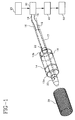
- FIGS. 1-3 illustrate several embodiments of an implantable device sensing catheter 10 having a balloon 12 disposed on the shaft 17 with one or more sensors 14 disposed on the balloon 12 .
- the sensing catheters 10 in FIGS. 1-3 are illustrated outside of a body lumen and in a substantially expanded state.
- the balloon 12 will be in a deflated state or in a minimally inflated state and inside a body lumen when the balloon 12 enters the stent 20 .
- the catheter 10 may be provided with the sensors 14 positioned on the catheter 10 and without a balloon 12 .
- the sensors 14 may be continuous or individual separate units or circuits. For either system, a signal may occur upon contact of the sensor 14 with the stent 20 during longitudinal or radial movement of the sensor 14 , expansion of the balloon 12 , or a combination thereof. Contact between the sensor 14 and the stent 20 will generally occur at the proximal edge of the stent 20 or at the inside surface of the stent 20 .
- the sensors 14 may be arranged on the catheter 10 or balloon 12 in predetermined patterns including longitudinal, circumferential, helical, curved, angular patterns, or combinations thereof.
- circumferential-shaped or U-shaped sensors 14 disposed on the balloon 12 may be used to correlate and define the position of the balloon 12 in relation to the stent 20 .
- the sensors 14 may be thermally, adhesively, or chemically disposed to the catheter 10 or balloon 12 .
- the sensors 14 are further connected to a conductive path 16 which conducts or carries signals from the sensor 14 to a connection 22 and then to a relay 25 , measurement device 30 , microprocessor 40 , or output device 50 .
- the sensors 14 are disposed on the balloon 12 surface and connected to a conductive path 16 .
- the conductive path 16 is connected to a connection 22 which runs through a wall 19 in the catheter shaft 17 .
- the connection 22 is further connected, for example, to a wire or conductive path 16 which runs along the catheter shaft 17 to the relay 25 , measurement device 30 , microprocessor 40 or output device 50 .
- One or more epoxy connections 22 including an epoxy-filled hole may be incorporated in the shaft 17 and circuit to make the electrical or conductive connections between the components of the system.
- the sensors 14 , conductive path 16 , and connection 22 may be made of a conductive wire, conductive paint, conductive polymer, vapor deposited metal, conductive coatings, conductive film, conductive epoxy, conductive metals, or other comparable conductive materials known in the art adaptable to carry an electrical signal.
- the sensors 14 and conductive path 16 may be made of the same material and disposed on the balloon 12 or catheter 10 using the same methods.
- the sensors 14 may be made of a material having greater resistance than the conductive path 16 .
- the shaft wires may be made of a low resistance wires such as copper and the sensor 14 may be made of conductive paint which has much more resistance than the shaft wires.
- the conductive path 16 may be conductive paint or conductive polymer which extends down the length of the catheter shaft 17 .
- the sensor 14 may have a resistance in the range of about 50 ⁇ (ohms) to about 2 K ⁇ (ohms).
- the sensor 14 or conductive path 16 may be made of materials having a resistance greater than 500 ⁇ (ohms) and up to 200 K ⁇ (kilo-ohms).
- the conductive path 16 may connect to a measurement device 30 such as an ohmmeter, voltage meter, or amperage meter.
- the ohmmeter may be connected to a microprocessor 40 that converts the signal to an audio signal, a video signal or image.
- the sensor circuit may include a microprocessor 40 programmed to output a signal to an output device 50 .
- the output device 50 may be any type of messaging medium including monitor, meter, speaker, indicator, imaging system, or display that provides an image, or some quantifiable information or measurement.
- the measurement device 30 may be the output device 50 .
- An output device 50 may be disposed on the proximal end of the catheter 10 to provide a reading of the balloon 12 / stent 20 relative locations.
- a movable indicator signifying the balloon 12 may be used in a fixed dial having an image of the stent 20 .
- the output device 50 shows their relative relationship and, accordingly, is advantageously understandable in most any language.
- a relay 25 may be incorporated in the circuit to forward the signal to at least one of the measurement device 30 , microprocessor device 40 , or output device 50 .
- the relay 25 may be adapted to make a wireless transmission of the signal.
- the microprocessor 40 may be programmed to calculate the location of the sensor 14 and balloon 12 relative to the stent 20 or to a particular region within the stent 20 .
- the signals from the sensors 14 are based on resistance, voltage or amperage. Signals may be forwarded from the measurement device 30 to a microprocessor 40 for further signal processing and thereafter forwarded to an output device 50 . Signals may be forwarded to the microprocessor 40 prior to transmission to the devices 30, 50 .
- the signal may be, for example, an on-off or variable signal depending on the amount of contact between the sensor 14 and the stent 20 .
- the signal may be dependent on the area of contact or a function of resistance of the sensor 14 with the stent 20 .
- the sensors 14 may have various longitudinal lengths, various areas, and resistance in order to provide a variety of signals to a user.
- the conductive path 16 may be thermally, adhesively, or chemically connected to the balloon 12 or catheter 10 and, for example, be soldered to the relay 25 which may be disposed on or in a portion of the catheter 10 .
- the relay 25 may be external to the catheter 10 .
- One or more conductive paths 16 may be extruded in the catheter wall 19 or may run as a bundle in a lumen, inflation lumen, or channel inside or outside the catheter shaft 17 .
- the sensor 14 or conductive path 16 for example, may be made of a low resistance material such as copper.
- a first signal may be produced and forwarded to the measurement device 30 , microprocessor 40 , or output device 50 when the balloon 14 is away from the stent 20 .
- One or more additional signals may be produced when the balloon 12 is at least partially disposed in the stent 20 , or upon contact between the stent 20 and the sensors 14 .
- the frequency of signals is dependent on the needs of the user.
- two sensors 14 are arranged and disposed in predetermined patterns, for example, generally parallel and circumferential positions, around a balloon 12 .
- the sensors 14 are preferably located at the shoulders of the balloon 12 , but many variations are possible.
- the sensor 14 may communicate a first signal to an output device 50 which in turn provides, for example, a first reading of zero corresponding to no contact between the sensors 14 and the stent 20 ; a second signal and reading may correspond to contact of the distal most sensor 14 on the balloon 12 and the stent 20 ; and a third signal and reading may correspond to contact of both sensors 14 and the stent 20 , i.e., both sensors 14 are at least partially disposed inside the stent 20 and contact has been made with the inside surface 21 of the stent 20 .
- a variety of signals from the output device 50 may advantageously be generated for the user.
- the balloon 12 may be directed distally in the body lumen to the deployed stent 20 , and partially inflated to a low pressure.
- a signal or reading at the measurement device 30 or output device 50 may indicate that the balloon 12 is at least partially disposed within the stent 20 .
- the signal may be an audio or visual signal communicating the relation of the catheter 10 or balloon 14 to the stent 20 . The physician will determine when the balloon 12 and stent 20 are in the desired relationship.
- the stent 20 may short out one or more of the sensors 14 upon contact with the conductive component of the implantable device and communicate a corresponding signal to the measurement device 30 , microprocessor 40 , or output device 50 .
- FIG. 2 illustrates a catheter 10 with a U-shaped sensors 14 disposed on the balloon 12 .
- the circumferential loops of the sensor 14 may have a full resistance of, for example, a value 2X.
- the stent 20 is over the distal end 12a or proximal end 12b of the balloon 12 and contact is made between the sensors 14 and the stent 20 , the stent 20 wires may short out the distal loop of the sensor 14 and the sensor 14 may have a resistance of, for example, a value X.
- the stent 20 when the stent 20 is over the proximal end 12b of the balloon 12 , the stent 20 wires may short out the proximal loop of the sensor 14 and the sensor 14 may have a resistance of, for example, a value X.
- the stent 20 When the stent 20 is substantially disposed over the balloon 12 and preferably centered, the stent 20 shorts out both loops of the sensors 14 and the sensor 14 may have a resistance of, for example, a value zero.
- the resistance measurements at the output device 50 would correspond or correlate to an equivalent location of the balloon 12 in relation to the stent 20 .
- the resistance value and balloon 12 / stent 20 location relationship may be linear.
- the sensor 14 has a resistance that is correspondingly lower.
- FIGS. 3A-D illustrate use of the sensing catheter 10 , specifically, progressive insertion of the distal portion 12a of the balloon 12 having one or more sensors 14 entering into the interior region of a stent 20 .
- a corresponding output from the measurement device 30 such as an ohmmeter, relates the position of the balloon 12 in relation to the stent 20 .
- the sensors 14 may be arranged such that the ohmmeter may display a high resistance or first signal when the stent 20 is not overlapping the balloon 12 ; a medium resistance or second signal when the stent 20 is partially overlapping the balloon 12 ; and a low resistance or third signal when the stent 20 is fully overlapping the balloon 12 .
- a kit for locating implantable devices may include an implantable device sensing catheter 10 having a balloon 12 with sensors 14 , and an output device 50 .
- a preferred method of dilatating a stent 20 includes the steps of inserting a stent 20 into a body vessel, inserting a catheter 10 having a balloon 12 and at least one sensor 14 adapted to produce one or more signals and forward the signals to a device 30, 50 for relating the location of a predetermined portion of the balloon 12 relative to the stent 20 , interpreting the output device 50 information at least once, manipulating the balloon 12 at least partially within the stent until the device 30, 50 relates the desired position of the balloon 12 relative to the stent 20 , and dilatating the balloon 12 at least once.
- the method for locating a stent 20 may include steps of watching a visual display or listening for an audible signal which informs the cardiologist as to when the balloon 12 is properly positioned.
- the method of positioning the balloon 12 may include partial inflation of the balloon 12 or positioning the balloon 12 while deflated.
- Another variation of the above method may include the step of interpreting the output device information at least once until the output device indicates that the dilatation balloon 12 is at least partially disposed or substantially disposed in the stent 20 . Also, one of the above steps may include use of a microprocessor 40 to calculate an audio or visual signal for the monitor or speaker.
- the implantable device sensing may be constructed using a number of methods and materials, in a wide variety of sizes and styles for the greater efficiency and convenience of a user.
Applications Claiming Priority (2)
| Application Number | Priority Date | Filing Date | Title |
|---|---|---|---|
| US3344596P | 1996-12-20 | 1996-12-20 | |
| US33445P | 1996-12-20 |
Publications (1)
| Publication Number | Publication Date |
|---|---|
| EP0850654A1 true EP0850654A1 (fr) | 1998-07-01 |
Family
ID=21870441
Family Applications (1)
| Application Number | Title | Priority Date | Filing Date |
|---|---|---|---|
| EP97309898A Withdrawn EP0850654A1 (fr) | 1996-12-20 | 1997-12-05 | Cathéter destiné à la détection d'un dispositif implantable |
Country Status (2)
| Country | Link |
|---|---|
| EP (1) | EP0850654A1 (fr) |
| JP (1) | JPH10179762A (fr) |
Cited By (3)
| Publication number | Priority date | Publication date | Assignee | Title |
|---|---|---|---|---|
| WO2001019239A1 (fr) | 1999-09-17 | 2001-03-22 | Endoluminal Therapeutics, Inc. | Implants medicaux permettant la telemetrie, la reponse, le stockage, l'interrogation et la detection |
| US6802811B1 (en) | 1999-09-17 | 2004-10-12 | Endoluminal Therapeutics, Inc. | Sensing, interrogating, storing, telemetering and responding medical implants |
| WO2013022853A1 (fr) * | 2011-08-05 | 2013-02-14 | Mc10, Inc. | Procédés de ballonnets de cathéter et appareil utilisant des éléments de détection |
Families Citing this family (1)
| Publication number | Priority date | Publication date | Assignee | Title |
|---|---|---|---|---|
| JP5795718B2 (ja) * | 2011-03-09 | 2015-10-14 | テルモ株式会社 | ステントデリバリーシステム |
Citations (21)
| Publication number | Priority date | Publication date | Assignee | Title |
|---|---|---|---|---|
| US4304239A (en) * | 1980-03-07 | 1981-12-08 | The Kendall Company | Esophageal probe with balloon electrode |
| US4522205A (en) * | 1980-09-03 | 1985-06-11 | The University Court Of The University Of Edinburgh | Therapeutic device and method of inducing thrombosis in a blood vessel |
| US4526177A (en) * | 1983-06-24 | 1985-07-02 | Rudy Michael A | Electronic anatomical probe |
| US4655771A (en) | 1982-04-30 | 1987-04-07 | Shepherd Patents S.A. | Prosthesis comprising an expansible or contractile tubular body |
| US4762129A (en) | 1984-11-23 | 1988-08-09 | Tassilo Bonzel | Dilatation catheter |
| DE3900178A1 (de) * | 1989-01-05 | 1990-07-12 | Paul Peter Prof D Lunkenheimer | Vorrichtung zur durchfuehrung diagnostischer impedanzmessungen |
| US5061275A (en) | 1986-04-21 | 1991-10-29 | Medinvent S.A. | Self-expanding prosthesis |
| US5120323A (en) | 1990-01-12 | 1992-06-09 | Schneider (Usa) Inc. | Telescoping guide catheter system |
| US5163906A (en) | 1988-09-27 | 1992-11-17 | Schneider (Europe) Ag | Dilatation catheter and method for widening of strictures |
| US5209729A (en) | 1990-08-09 | 1993-05-11 | Schneider (Europe) Ag | Dilatation catheter |
| EP0545739A1 (fr) * | 1991-12-06 | 1993-06-09 | Nagao Kajiwara | Appareil de surveillance de l'électrocardiogramme bronchial |
| US5232445A (en) | 1984-11-23 | 1993-08-03 | Tassilo Bonzel | Dilatation catheter |
| US5306247A (en) | 1991-12-11 | 1994-04-26 | Schneider (Europe) A.G. | Balloon catheter |
| WO1994016646A1 (fr) | 1993-01-19 | 1994-08-04 | Schneider (Usa) Inc. | Extenseur en materiau composite avec gainage |
| WO1994024931A1 (fr) * | 1993-05-05 | 1994-11-10 | Arrow International Investment Corp. | Catheter portant electrode et procede de fabrication |
| US5403292A (en) | 1994-05-18 | 1995-04-04 | Schneider (Usa) Inc. | Thin wall catheter having enhanced torqueability characteristics |
| US5411016A (en) * | 1994-02-22 | 1995-05-02 | Scimed Life Systems, Inc. | Intravascular balloon catheter for use in combination with an angioscope |
| US5505699A (en) | 1994-03-24 | 1996-04-09 | Schneider (Usa) Inc. | Angioplasty device |
| US5630840A (en) | 1993-01-19 | 1997-05-20 | Schneider (Usa) Inc | Clad composite stent |
| US5645559A (en) | 1992-05-08 | 1997-07-08 | Schneider (Usa) Inc | Multiple layer stent |
| WO1997032545A1 (fr) * | 1996-03-07 | 1997-09-12 | Scimed Life Systems, Inc. | Dispositif de localisation de protheses endovasculaires |
-
1997
- 1997-12-05 EP EP97309898A patent/EP0850654A1/fr not_active Withdrawn
- 1997-12-18 JP JP34922197A patent/JPH10179762A/ja active Pending
Patent Citations (24)
| Publication number | Priority date | Publication date | Assignee | Title |
|---|---|---|---|---|
| US4304239A (en) * | 1980-03-07 | 1981-12-08 | The Kendall Company | Esophageal probe with balloon electrode |
| US4522205A (en) * | 1980-09-03 | 1985-06-11 | The University Court Of The University Of Edinburgh | Therapeutic device and method of inducing thrombosis in a blood vessel |
| US4655771A (en) | 1982-04-30 | 1987-04-07 | Shepherd Patents S.A. | Prosthesis comprising an expansible or contractile tubular body |
| US4655771B1 (en) | 1982-04-30 | 1996-09-10 | Medinvent Ams Sa | Prosthesis comprising an expansible or contractile tubular body |
| US4526177A (en) * | 1983-06-24 | 1985-07-02 | Rudy Michael A | Electronic anatomical probe |
| US5232445A (en) | 1984-11-23 | 1993-08-03 | Tassilo Bonzel | Dilatation catheter |
| US4762129A (en) | 1984-11-23 | 1988-08-09 | Tassilo Bonzel | Dilatation catheter |
| US4762129B1 (fr) | 1984-11-23 | 1991-07-02 | Tassilo Bonzel | |
| US5061275A (en) | 1986-04-21 | 1991-10-29 | Medinvent S.A. | Self-expanding prosthesis |
| US5163906A (en) | 1988-09-27 | 1992-11-17 | Schneider (Europe) Ag | Dilatation catheter and method for widening of strictures |
| DE3900178A1 (de) * | 1989-01-05 | 1990-07-12 | Paul Peter Prof D Lunkenheimer | Vorrichtung zur durchfuehrung diagnostischer impedanzmessungen |
| US5120323A (en) | 1990-01-12 | 1992-06-09 | Schneider (Usa) Inc. | Telescoping guide catheter system |
| US5209729A (en) | 1990-08-09 | 1993-05-11 | Schneider (Europe) Ag | Dilatation catheter |
| EP0545739A1 (fr) * | 1991-12-06 | 1993-06-09 | Nagao Kajiwara | Appareil de surveillance de l'électrocardiogramme bronchial |
| US5306247A (en) | 1991-12-11 | 1994-04-26 | Schneider (Europe) A.G. | Balloon catheter |
| US5645559A (en) | 1992-05-08 | 1997-07-08 | Schneider (Usa) Inc | Multiple layer stent |
| WO1994016646A1 (fr) | 1993-01-19 | 1994-08-04 | Schneider (Usa) Inc. | Extenseur en materiau composite avec gainage |
| US5630840A (en) | 1993-01-19 | 1997-05-20 | Schneider (Usa) Inc | Clad composite stent |
| WO1994024931A1 (fr) * | 1993-05-05 | 1994-11-10 | Arrow International Investment Corp. | Catheter portant electrode et procede de fabrication |
| US5411016A (en) * | 1994-02-22 | 1995-05-02 | Scimed Life Systems, Inc. | Intravascular balloon catheter for use in combination with an angioscope |
| US5505699A (en) | 1994-03-24 | 1996-04-09 | Schneider (Usa) Inc. | Angioplasty device |
| US5403292A (en) | 1994-05-18 | 1995-04-04 | Schneider (Usa) Inc. | Thin wall catheter having enhanced torqueability characteristics |
| US5599325A (en) | 1994-05-18 | 1997-02-04 | Schneider (Usa) Inc | Thin wall catheter with reinforcing sleeve |
| WO1997032545A1 (fr) * | 1996-03-07 | 1997-09-12 | Scimed Life Systems, Inc. | Dispositif de localisation de protheses endovasculaires |
Cited By (3)
| Publication number | Priority date | Publication date | Assignee | Title |
|---|---|---|---|---|
| WO2001019239A1 (fr) | 1999-09-17 | 2001-03-22 | Endoluminal Therapeutics, Inc. | Implants medicaux permettant la telemetrie, la reponse, le stockage, l'interrogation et la detection |
| US6802811B1 (en) | 1999-09-17 | 2004-10-12 | Endoluminal Therapeutics, Inc. | Sensing, interrogating, storing, telemetering and responding medical implants |
| WO2013022853A1 (fr) * | 2011-08-05 | 2013-02-14 | Mc10, Inc. | Procédés de ballonnets de cathéter et appareil utilisant des éléments de détection |
Also Published As
| Publication number | Publication date |
|---|---|
| JPH10179762A (ja) | 1998-07-07 |
Similar Documents
| Publication | Publication Date | Title |
|---|---|---|
| US5665103A (en) | Stent locating device | |
| US20070265637A1 (en) | Devices and methods for controlling and counting interventional elements | |
| US6612998B2 (en) | Guide wire with marker sleeve | |
| US6428512B1 (en) | Guidewire with improved lesion measurement | |
| US6078832A (en) | Lesion measurement catheter and method | |
| US8641748B2 (en) | Guidewire loaded stent for delivery through a catheter | |
| US6585755B2 (en) | Polymeric stent suitable for imaging by MRI and fluoroscopy | |
| US8083692B2 (en) | Lumen-measuring devices and method | |
| US6091980A (en) | Stent slip sensing system and method | |
| White et al. | Intravascular ultrasound: the ultimate tool for abdominal aortic aneurysm assessment and endovascular graft delivery | |
| WO1997042871A1 (fr) | Catheter et procede pour mesurer le diametre d'une lesion | |
| CN106170245B (zh) | 腔内孔口传感器阵列装置 | |
| WO2006127997A2 (fr) | Systeme d'implantation de prothese endovasculaire a bifurcation | |
| EP1339355A2 (fr) | Catheter a ballonnet avec extremite distale radio-opaque | |
| JPH09510125A (ja) | 放射線不透過性のマーカーを具備するカテーテル用ガイドワイヤ | |
| JP2017505704A (ja) | 位置合わせを容易にするためのマーキングを有するアンカー付ガイドワイヤ | |
| EP0850654A1 (fr) | Cathéter destiné à la détection d'un dispositif implantable | |
| US5800443A (en) | Apparatus and method for localizing prostheses deployed in a body lumen | |
| US6099533A (en) | Apparatus and method for localizing prosthesis deployed in a body lumen | |
| CA2262352C (fr) | Mise en place guidee de tuteurs |
Legal Events
| Date | Code | Title | Description |
|---|---|---|---|
| PUAI | Public reference made under article 153(3) epc to a published international application that has entered the european phase |
Free format text: ORIGINAL CODE: 0009012 |
|
| AK | Designated contracting states |
Kind code of ref document: A1 Designated state(s): DE FR GB IT |
|
| AX | Request for extension of the european patent |
Free format text: AL;LT;LV;MK;RO;SI |
|
| AKX | Designation fees paid |
Free format text: DE FR GB IT |
|
| RBV | Designated contracting states (corrected) |
Designated state(s): DE FR GB IT |
|
| STAA | Information on the status of an ep patent application or granted ep patent |
Free format text: STATUS: THE APPLICATION IS DEEMED TO BE WITHDRAWN |
|
| 18D | Application deemed to be withdrawn |
Effective date: 19990202 |