EP0850424B1 - Difar sensor - Google Patents
Difar sensor Download PDFInfo
- Publication number
- EP0850424B1 EP0850424B1 EP96930231A EP96930231A EP0850424B1 EP 0850424 B1 EP0850424 B1 EP 0850424B1 EP 96930231 A EP96930231 A EP 96930231A EP 96930231 A EP96930231 A EP 96930231A EP 0850424 B1 EP0850424 B1 EP 0850424B1
- Authority
- EP
- European Patent Office
- Prior art keywords
- sensing element
- inertial mass
- sensor
- difar
- sensors
- Prior art date
- Legal status (The legal status is an assumption and is not a legal conclusion. Google has not performed a legal analysis and makes no representation as to the accuracy of the status listed.)
- Expired - Lifetime
Links
Images
Classifications
-
- G—PHYSICS
- G01—MEASURING; TESTING
- G01V—GEOPHYSICS; GRAVITATIONAL MEASUREMENTS; DETECTING MASSES OR OBJECTS; TAGS
- G01V1/00—Seismology; Seismic or acoustic prospecting or detecting
- G01V1/16—Receiving elements for seismic signals; Arrangements or adaptations of receiving elements
- G01V1/18—Receiving elements, e.g. seismometer, geophone or torque detectors, for localised single point measurements
- G01V1/186—Hydrophones
-
- G—PHYSICS
- G01—MEASURING; TESTING
- G01S—RADIO DIRECTION-FINDING; RADIO NAVIGATION; DETERMINING DISTANCE OR VELOCITY BY USE OF RADIO WAVES; LOCATING OR PRESENCE-DETECTING BY USE OF THE REFLECTION OR RERADIATION OF RADIO WAVES; ANALOGOUS ARRANGEMENTS USING OTHER WAVES
- G01S3/00—Direction-finders for determining the direction from which infrasonic, sonic, ultrasonic or electromagnetic waves, or particle emission, not having a directional significance, are being received
- G01S3/80—Direction-finders for determining the direction from which infrasonic, sonic, ultrasonic or electromagnetic waves, or particle emission, not having a directional significance, are being received using ultrasonic, sonic or infrasonic waves
- G01S3/801—Details
Definitions
- DIFAR sensors such as DIFAR hydrophones
- DIFAR hydrophones have been used in sonobuoys for approximately twenty years.
- a known DIFAR hydrophone is described in US-4928263 and EP 375,304.
- the hydrophone described therein comprises a hollow shell containing a mounting element from which an inertial mass is suspended by a relatively stiff suspension.
- the mounting element typically has a mass several times (often 10 or more) greater than that of the inertial mass.
- the inertial mass has four upwardly extending pins arranged in a cruciform fashion which engage piezoelectric elements which detect wobble of the inertial mass relative to the mounting element.
- screw threaded adjusters are used to adjust the force acting between the inertial mass and the piezoelectric elements.
- a pressure wave impinging upon the surface of the sonobuoy is required to accelerate both the waterproof housing and the mounting element in order to induce relative motion of the mounting element and the inertial mass.
- a DIFAR sensor comprising an inertial mass, a sensing element upon which a surrounding medium exerts a pressure and which, in use, undergoes displacement in response to an acoustic pressure wave acting thereon, and a plurality of sensors, characterised in that the sensing element defines, in part, an external surface of the sensor, a further part of the external surface is defined by an end cap which forms part of the inertial mass, the sensors sense motion of the sensing element relative to the inertial mass and the mass of the sensing element is less than the mass of the inertial mass
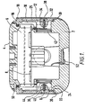
- the sensing element 30 has four equally spaced inwardly facing projections formed thereon.
- Two projections 34 and 36 are illustrated in Figure 1.
- Each projection 34 and 36 has a screw threaded passage therein which extends between an innermost portion of the projection and an associated access hole formed in the sensing element 30 and the elastomeric skin 32.
- Screw threaded adjustment elements 38 and 40 provide adjustable projections that project inwardly of the sensing element 30. After adjustment of the elements 38 and 40, the outer surface thereof is sealed against the environment by elastomeric plugs and adhesive.
- a ring seal 50 is provided between the top 4 and the retaining ring 16 so as to prevent the ingress of fluid within the chamber 6.
- the base 2, ring 16 and the sensing element 30 may be made of aluminium while the top 4 may be made of zinc.
- the sensing element 30 has a mass of approximately one tenth of the mass of the inertial mass (i.e. base 2, top 4 and ring 16).
- the inertial mass formed by the bottom 2, the top 4, and the ring 16 and the processing electronics, will tend to remain unperturbed, and hence the acoustic pressure wave will introduce relative movement between the sensing element 30 and the inertial mass.
- This motion is transmitted to the piezoelectric sensors via the screw threaded elements extending between the piezoelectric sensors and the sensing element 30, and consequently an electrical signal is generated in response to relative movement of the sensing element.
- a pair of piezoelectric sensors By arranging for a pair of piezoelectric sensors to be diagonally opposite one another within the inertial mass until, a displacement of the shell along the line between the opposing piezoelectric sensors will cause the sensors to be deflected in opposite senses.
- the signals resulting from motion of the sensing element 30 can be arranged to add constructively if the opposing piezoelectric elements are attached with their directions of polarisation in mutual opposition.
- displacement of the sensing element 30 can be resolved into two orthogonal directions so as to define a line of acoustic propagation from the ratio of the displacements along the orthogonal directions. This leaves an ambiguity in the direction of the line of propagation.
- this can be resolved by the addition of a conventional hydrophone measuring the acoustic pressure wave directly.
- a magnetic compass within the body of the DIFAR sensor, it is possible to relate the direction of propagation to a magnetic bearing.
- Such a combination of two orthogonal sensors (formed by sensor pairs) plus an omnidirectional hydrophone) is known in conventional DIFAR sonobuoys.
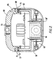
- Figure 2 illustrates an alternative embodiment of the present invention.
- the inertial mass is divided into an upper portion 60 and a lower portion 62 which are removably connected to one another and define a chamber 64.
- the lower inertial mass portion 62 has a downwardly extending cylindrical portion 66 which carries four diaphragms equally spaced about its periphery, each diaphragm carrying a piezoelectric transducer.
- the sensing element 30 is modified by the provision of an end cap 30' so as to form a dome.
- the dome encloses a volume 69.
Landscapes
- Engineering & Computer Science (AREA)
- Remote Sensing (AREA)
- Physics & Mathematics (AREA)
- Life Sciences & Earth Sciences (AREA)
- General Physics & Mathematics (AREA)
- Geology (AREA)
- Environmental & Geological Engineering (AREA)
- General Life Sciences & Earth Sciences (AREA)
- Acoustics & Sound (AREA)
- Geophysics (AREA)
- Radar, Positioning & Navigation (AREA)
- Measurement Of Velocity Or Position Using Acoustic Or Ultrasonic Waves (AREA)
- Measurement Of Mechanical Vibrations Or Ultrasonic Waves (AREA)
Description
Claims (13)
- A DIFAR sensor comprising an inertial mass (2, 4, 60, 62), a sensing element (30) upon which a surrounding medium exerts a pressure and which, in use, undergoes displacement in response to an acoustic pressure wave acting thereon, and a plurality of sensors (42, 44), characterised in that the sensing element (30) defines, in part, an external surface of the sensor, a further part of the external surface is defined by an end cap (2, 4) which forms part of the inertial mass, the sensors sense motion of the sensing element relative to the inertial mass and the mass of the sensing element (30) is less than the mass of the inertial mass (2, 4).
- A DIFAR sensor as claimed in claim 1, characterised in that the mass of the inertial mass (2, 4 ; 60, 62) is more than ten times the mass of the sensing element.
- A DIFAR sensor as claimed in claim 1 or 2, characterised in that the wall portion is a cylindrical wall coaxially mounted with the inertial mass (2, 4 ; 60, 62).
- A DIFAR sensor as claimed in any one of the preceding claims, characterised in that the sensing element (30) has an integrally formed end cap (30/).
- A DIFAR sensor as claimed in any one of claims 1 to 3, characterised in that the sensing element (30) comprises an annular ring located between opposing sensor end portions (2, 4) which co-operate to form the inertial mass.
- A DIFAR sensor as claimed in any one of the preceding claims, characterised in that the sensing element (30) is in floating contact with the inertial mass (2, 4 ; 60, 62).
- A DIFAR sensor as claimed in any one of the preceding claims, characterised in that the sensing element (30) is connected to the inertial mass (2, 4 ; 60, 62) by an elastomeric element which serves to urge the sensing element towards a predetermined rest position with respect to the inertial mass, but which also allows limited relative movement between the sensing element (30) and the inertial mass (2, 4 ; 60, 62).
- A DIFAR sensor as claimed in any one of the preceding claims, characterised in that the sensing element (30) carries radially inwardly facing projections (34, 36) which cooperate with respective sensors.
- A DIFAR sensor as claimed in claim 8, characterised in that the projections (34, 36) carry adjustment means, whereby the force exerted on an associated sensor can be adjusted whilst the sensing element (30) is at its rest position.
- A DIFAR sensor as claimed in claim 9, characterised in that the adjustment means can be adjusted via access ports formed in the sensing element (30) such that adjustments can be made after the DIFAR sensor has been assembled.
- A DIFAR sensor as claimed in any one of the preceding claims, characterised in that the sensors (42, 44) are strain gauges or displacement sensors.
- A DIFAR sensor as claimed in any one of claims 1 to 8, characterised in that the sensors operate in a non-contact mode.
- A DIFAR sensor as claimed in claim 12, characterised in that the sensors are optical, electrical, magnetic or capacitive sensors.
Applications Claiming Priority (3)
| Application Number | Priority Date | Filing Date | Title |
|---|---|---|---|
| GB9518528A GB2305065B (en) | 1995-09-11 | 1995-09-11 | Difar sensor |
| GB9518528 | 1995-09-11 | ||
| PCT/GB1996/002207 WO1997010518A1 (en) | 1995-09-11 | 1996-09-06 | Difar sensor |
Publications (2)
| Publication Number | Publication Date |
|---|---|
| EP0850424A1 EP0850424A1 (en) | 1998-07-01 |
| EP0850424B1 true EP0850424B1 (en) | 2001-10-31 |
Family
ID=10780519
Family Applications (1)
| Application Number | Title | Priority Date | Filing Date |
|---|---|---|---|
| EP96930231A Expired - Lifetime EP0850424B1 (en) | 1995-09-11 | 1996-09-06 | Difar sensor |
Country Status (7)
| Country | Link |
|---|---|
| US (1) | US5949742A (en) |
| EP (1) | EP0850424B1 (en) |
| JP (1) | JP3140468B2 (en) |
| AU (1) | AU704177B2 (en) |
| CA (1) | CA2230190A1 (en) |
| GB (1) | GB2305065B (en) |
| WO (1) | WO1997010518A1 (en) |
Families Citing this family (7)
| Publication number | Priority date | Publication date | Assignee | Title |
|---|---|---|---|---|
| US7310287B2 (en) | 2003-05-30 | 2007-12-18 | Fairfield Industries Incorporated | Method and apparatus for seismic data acquisition |
| US8098546B2 (en) * | 2009-07-08 | 2012-01-17 | Geospace Technologies, Lp | Geophone having improved sensitivity |
| US8050144B2 (en) * | 2009-07-08 | 2011-11-01 | Geospace Technologies Lp | Vertical geophone having improved distortion characteristics |
| US8208347B2 (en) * | 2009-07-08 | 2012-06-26 | Geospace Technologies, Lp | Geophone having improved damping control |
| US8681587B2 (en) * | 2012-03-29 | 2014-03-25 | Rensselaer Polytechnic Institute | Method and apparatus for an acoustic-electric channel mounting |
| KR102347260B1 (en) * | 2019-08-27 | 2022-01-05 | 소나테크 주식회사 | Difar sensor housing and apparatus for disassembling the difar sensor housing |
| KR102220882B1 (en) * | 2019-09-27 | 2021-02-26 | 소나테크 주식회사 | Apparatus for assembling difar sensor housing |
Family Cites Families (8)
| Publication number | Priority date | Publication date | Assignee | Title |
|---|---|---|---|---|
| US3803546A (en) * | 1966-12-21 | 1974-04-09 | Us Navy | Broad band hydrophone |
| US3739202A (en) * | 1970-08-28 | 1973-06-12 | W Cady | Instrument for responding to mechanical vibration of acceleration andfor converting the same into electric energy |
| JPS5851478B2 (en) * | 1979-04-26 | 1983-11-16 | 沖電気工業株式会社 | directional receiver |
| US4326275A (en) * | 1979-09-27 | 1982-04-20 | Hazeltine Corporation | Directional transducer |
| JPS5719624A (en) * | 1980-07-09 | 1982-02-01 | Mitsubishi Electric Corp | Device for measuring vibration |
| US4709359A (en) * | 1982-06-28 | 1987-11-24 | Magnovox Government And Industrial Electronics Company | End weighted reed sound transducer |
| CA1321827C (en) * | 1988-12-19 | 1993-08-31 | Bruce A. Armstrong | Hydrophones and similar devices |
| US5392258A (en) * | 1993-10-12 | 1995-02-21 | The United States Of America As Represented By The Secretary Of The Navy | Underwater acoustic intensity probe |
-
1995
- 1995-09-11 GB GB9518528A patent/GB2305065B/en not_active Expired - Fee Related
-
1996
- 1996-09-06 CA CA002230190A patent/CA2230190A1/en not_active Abandoned
- 1996-09-06 US US09/011,140 patent/US5949742A/en not_active Expired - Fee Related
- 1996-09-06 EP EP96930231A patent/EP0850424B1/en not_active Expired - Lifetime
- 1996-09-06 WO PCT/GB1996/002207 patent/WO1997010518A1/en not_active Ceased
- 1996-09-06 JP JP09511740A patent/JP3140468B2/en not_active Expired - Fee Related
-
1997
- 1997-12-22 AU AU48555/97A patent/AU704177B2/en not_active Ceased
Also Published As
| Publication number | Publication date |
|---|---|
| GB2305065B (en) | 1999-04-21 |
| GB9518528D0 (en) | 1996-10-02 |
| EP0850424A1 (en) | 1998-07-01 |
| GB2305065A (en) | 1997-03-26 |
| WO1997010518A1 (en) | 1997-03-20 |
| US5949742A (en) | 1999-09-07 |
| CA2230190A1 (en) | 1997-03-20 |
| JPH11513480A (en) | 1999-11-16 |
| AU4855597A (en) | 1998-07-02 |
| AU704177B2 (en) | 1999-04-15 |
| JP3140468B2 (en) | 2001-03-05 |
Similar Documents
| Publication | Publication Date | Title |
|---|---|---|
| US5317929A (en) | Fiber optic flexural disk accelerometer | |
| US4163206A (en) | Apparatus and method for seismic wave detection | |
| EP0375304B1 (en) | Hydrophone and similar sensor | |
| US5392258A (en) | Underwater acoustic intensity probe | |
| US6160763A (en) | Towed array hydrophone | |
| US6128251A (en) | Solid marine seismic cable | |
| US5126980A (en) | Self-orienting vertically sensitive accelerometer | |
| US5949742A (en) | DIFAR sensor | |
| US10448181B2 (en) | Method of manufacturing a low density underwater accelerometer | |
| JP4864888B2 (en) | Vibration sensor | |
| US4827459A (en) | High sensitivity accelerometer for crossed dipoles acoustic sensors | |
| US5046056A (en) | Self-orienting vertically sensitive accelerometer | |
| US7536913B2 (en) | Rigidly mounted underwater acoustic inertial vector sensor | |
| US6151277A (en) | Hydrophone with ferroelectric sensor | |
| RU2708184C1 (en) | Combined vector receiver | |
| EP3724692B1 (en) | Seismic pressure and acceleration sensor | |
| JPH08304163A (en) | Vibration detector | |
| US4208737A (en) | Low frequency inertia balanced dipole hydrophone | |
| US5084846A (en) | Deep submergence hydrophone | |
| US20250306190A1 (en) | Acoustic vector sensor | |
| CA1108744A (en) | Low frequency inertia balanced dipole hydrophone | |
| HK1007801B (en) | Hydrophone and similar sensor | |
| IE46597B1 (en) | Seismic method and apparatus | |
| McCleary et al. | A sensor for measuring low frequency surface vibration of a fluid loaded compliant structure | |
| JPH0949755A (en) | Vibration sensor |
Legal Events
| Date | Code | Title | Description |
|---|---|---|---|
| PUAI | Public reference made under article 153(3) epc to a published international application that has entered the european phase |
Free format text: ORIGINAL CODE: 0009012 |
|
| 17P | Request for examination filed |
Effective date: 19980206 |
|
| AK | Designated contracting states |
Kind code of ref document: A1 Designated state(s): FR GB SE |
|
| 17Q | First examination report despatched |
Effective date: 19990630 |
|
| GRAG | Despatch of communication of intention to grant |
Free format text: ORIGINAL CODE: EPIDOS AGRA |
|
| GRAG | Despatch of communication of intention to grant |
Free format text: ORIGINAL CODE: EPIDOS AGRA |
|
| GRAH | Despatch of communication of intention to grant a patent |
Free format text: ORIGINAL CODE: EPIDOS IGRA |
|
| GRAH | Despatch of communication of intention to grant a patent |
Free format text: ORIGINAL CODE: EPIDOS IGRA |
|
| GRAA | (expected) grant |
Free format text: ORIGINAL CODE: 0009210 |
|
| AK | Designated contracting states |
Kind code of ref document: B1 Designated state(s): FR GB SE |
|
| REG | Reference to a national code |
Ref country code: GB Ref legal event code: IF02 |
|
| ET | Fr: translation filed | ||
| PLBE | No opposition filed within time limit |
Free format text: ORIGINAL CODE: 0009261 |
|
| STAA | Information on the status of an ep patent application or granted ep patent |
Free format text: STATUS: NO OPPOSITION FILED WITHIN TIME LIMIT |
|
| 26N | No opposition filed | ||
| PGFP | Annual fee paid to national office [announced via postgrant information from national office to epo] |
Ref country code: GB Payment date: 20030722 Year of fee payment: 8 |
|
| PGFP | Annual fee paid to national office [announced via postgrant information from national office to epo] |
Ref country code: FR Payment date: 20030828 Year of fee payment: 8 |
|
| PGFP | Annual fee paid to national office [announced via postgrant information from national office to epo] |
Ref country code: SE Payment date: 20030904 Year of fee payment: 8 |
|
| PG25 | Lapsed in a contracting state [announced via postgrant information from national office to epo] |
Ref country code: GB Free format text: LAPSE BECAUSE OF NON-PAYMENT OF DUE FEES Effective date: 20040906 |
|
| PG25 | Lapsed in a contracting state [announced via postgrant information from national office to epo] |
Ref country code: SE Free format text: LAPSE BECAUSE OF NON-PAYMENT OF DUE FEES Effective date: 20040907 |
|
| GBPC | Gb: european patent ceased through non-payment of renewal fee |
Effective date: 20040906 |
|
| EUG | Se: european patent has lapsed | ||
| PG25 | Lapsed in a contracting state [announced via postgrant information from national office to epo] |
Ref country code: FR Free format text: LAPSE BECAUSE OF NON-PAYMENT OF DUE FEES Effective date: 20050531 |
|
| REG | Reference to a national code |
Ref country code: FR Ref legal event code: ST |