EP0850015B1 - A multipolar transmural probe - Google Patents
A multipolar transmural probe Download PDFInfo
- Publication number
- EP0850015B1 EP0850015B1 EP96925601A EP96925601A EP0850015B1 EP 0850015 B1 EP0850015 B1 EP 0850015B1 EP 96925601 A EP96925601 A EP 96925601A EP 96925601 A EP96925601 A EP 96925601A EP 0850015 B1 EP0850015 B1 EP 0850015B1
- Authority
- EP
- European Patent Office
- Prior art keywords
- probe
- tissue
- electrode
- elongated body
- electrodes
- Prior art date
- Legal status (The legal status is an assumption and is not a legal conclusion. Google has not performed a legal analysis and makes no representation as to the accuracy of the status listed.)
- Expired - Lifetime
Links
- 239000000523 sample Substances 0.000 title claims abstract description 66
- 239000000463 material Substances 0.000 claims abstract description 17
- 239000004020 conductor Substances 0.000 claims abstract description 16
- 239000002184 metal Substances 0.000 claims abstract description 11
- 229910052751 metal Inorganic materials 0.000 claims abstract description 11
- 239000011159 matrix material Substances 0.000 claims abstract description 9
- 230000035515 penetration Effects 0.000 claims abstract description 7
- 238000004519 manufacturing process Methods 0.000 claims abstract description 6
- 238000007674 radiofrequency ablation Methods 0.000 claims abstract description 6
- 230000009969 flowable effect Effects 0.000 claims description 7
- 238000000034 method Methods 0.000 claims description 6
- 239000003822 epoxy resin Substances 0.000 claims description 3
- 229920000647 polyepoxide Polymers 0.000 claims description 3
- 239000000126 substance Substances 0.000 claims description 3
- 229910000831 Steel Inorganic materials 0.000 claims description 2
- 230000006835 compression Effects 0.000 claims description 2
- 238000007906 compression Methods 0.000 claims description 2
- 239000007787 solid Substances 0.000 claims description 2
- 239000010959 steel Substances 0.000 claims description 2
- 210000001519 tissue Anatomy 0.000 description 25
- 210000004165 myocardium Anatomy 0.000 description 12
- 210000003205 muscle Anatomy 0.000 description 6
- 238000002679 ablation Methods 0.000 description 4
- 230000002950 deficient Effects 0.000 description 4
- 238000012986 modification Methods 0.000 description 4
- 230000004048 modification Effects 0.000 description 4
- 229910001220 stainless steel Inorganic materials 0.000 description 4
- 239000010935 stainless steel Substances 0.000 description 4
- 229920006362 Teflon® Polymers 0.000 description 3
- 206010003119 arrhythmia Diseases 0.000 description 3
- 230000006793 arrhythmia Effects 0.000 description 3
- 239000003814 drug Substances 0.000 description 3
- 229940079593 drug Drugs 0.000 description 3
- 210000003462 vein Anatomy 0.000 description 3
- PXHVJJICTQNCMI-UHFFFAOYSA-N Nickel Chemical compound [Ni] PXHVJJICTQNCMI-UHFFFAOYSA-N 0.000 description 2
- 239000004809 Teflon Substances 0.000 description 2
- 230000008859 change Effects 0.000 description 2
- 230000000694 effects Effects 0.000 description 2
- 230000007246 mechanism Effects 0.000 description 2
- 238000012544 monitoring process Methods 0.000 description 2
- BFKJFAAPBSQJPD-UHFFFAOYSA-N tetrafluoroethene Chemical compound FC(F)=C(F)F BFKJFAAPBSQJPD-UHFFFAOYSA-N 0.000 description 2
- 241000777300 Congiopodidae Species 0.000 description 1
- 241000124008 Mammalia Species 0.000 description 1
- 206010028980 Neoplasm Diseases 0.000 description 1
- 230000002159 abnormal effect Effects 0.000 description 1
- 230000005856 abnormality Effects 0.000 description 1
- 230000009471 action Effects 0.000 description 1
- 230000036982 action potential Effects 0.000 description 1
- 238000010009 beating Methods 0.000 description 1
- 239000008280 blood Substances 0.000 description 1
- 210000004369 blood Anatomy 0.000 description 1
- 210000004556 brain Anatomy 0.000 description 1
- 230000000747 cardiac effect Effects 0.000 description 1
- 239000011248 coating agent Substances 0.000 description 1
- 238000000576 coating method Methods 0.000 description 1
- 238000010276 construction Methods 0.000 description 1
- 230000008602 contraction Effects 0.000 description 1
- 238000005520 cutting process Methods 0.000 description 1
- 230000007547 defect Effects 0.000 description 1
- 238000000151 deposition Methods 0.000 description 1
- 238000001514 detection method Methods 0.000 description 1
- 210000005003 heart tissue Anatomy 0.000 description 1
- 238000010348 incorporation Methods 0.000 description 1
- 238000003780 insertion Methods 0.000 description 1
- 230000037431 insertion Effects 0.000 description 1
- 230000001788 irregular Effects 0.000 description 1
- 238000005259 measurement Methods 0.000 description 1
- 230000004118 muscle contraction Effects 0.000 description 1
- 230000036403 neuro physiology Effects 0.000 description 1
- 229910052759 nickel Inorganic materials 0.000 description 1
- 230000000149 penetrating effect Effects 0.000 description 1
- 230000008569 process Effects 0.000 description 1
- 238000004544 sputter deposition Methods 0.000 description 1
- 238000001356 surgical procedure Methods 0.000 description 1
- 210000000779 thoracic wall Anatomy 0.000 description 1
- 238000009966 trimming Methods 0.000 description 1
- 206010047302 ventricular tachycardia Diseases 0.000 description 1
- 238000003466 welding Methods 0.000 description 1
Images


Classifications
-
- A—HUMAN NECESSITIES
- A61—MEDICAL OR VETERINARY SCIENCE; HYGIENE
- A61B—DIAGNOSIS; SURGERY; IDENTIFICATION
- A61B5/00—Measuring for diagnostic purposes; Identification of persons
- A61B5/24—Detecting, measuring or recording bioelectric or biomagnetic signals of the body or parts thereof
- A61B5/25—Bioelectric electrodes therefor
- A61B5/279—Bioelectric electrodes therefor specially adapted for particular uses
- A61B5/28—Bioelectric electrodes therefor specially adapted for particular uses for electrocardiography [ECG]
- A61B5/283—Invasive
- A61B5/287—Holders for multiple electrodes, e.g. electrode catheters for electrophysiological study [EPS]
-
- A—HUMAN NECESSITIES
- A61—MEDICAL OR VETERINARY SCIENCE; HYGIENE
- A61B—DIAGNOSIS; SURGERY; IDENTIFICATION
- A61B5/00—Measuring for diagnostic purposes; Identification of persons
- A61B5/68—Arrangements of detecting, measuring or recording means, e.g. sensors, in relation to patient
- A61B5/6846—Arrangements of detecting, measuring or recording means, e.g. sensors, in relation to patient specially adapted to be brought in contact with an internal body part, i.e. invasive
- A61B5/6847—Arrangements of detecting, measuring or recording means, e.g. sensors, in relation to patient specially adapted to be brought in contact with an internal body part, i.e. invasive mounted on an invasive device
- A61B5/6848—Needles
-
- A—HUMAN NECESSITIES
- A61—MEDICAL OR VETERINARY SCIENCE; HYGIENE
- A61N—ELECTROTHERAPY; MAGNETOTHERAPY; RADIATION THERAPY; ULTRASOUND THERAPY
- A61N1/00—Electrotherapy; Circuits therefor
- A61N1/02—Details
- A61N1/04—Electrodes
- A61N1/06—Electrodes for high-frequency therapy
-
- A—HUMAN NECESSITIES
- A61—MEDICAL OR VETERINARY SCIENCE; HYGIENE
- A61B—DIAGNOSIS; SURGERY; IDENTIFICATION
- A61B17/00—Surgical instruments, devices or methods
- A61B2017/00017—Electrical control of surgical instruments
- A61B2017/00022—Sensing or detecting at the treatment site
- A61B2017/00039—Electric or electromagnetic phenomena other than conductivity, e.g. capacity, inductivity, Hall effect
- A61B2017/00044—Sensing electrocardiography, i.e. ECG
-
- A—HUMAN NECESSITIES
- A61—MEDICAL OR VETERINARY SCIENCE; HYGIENE
- A61B—DIAGNOSIS; SURGERY; IDENTIFICATION
- A61B17/00—Surgical instruments, devices or methods
- A61B17/00234—Surgical instruments, devices or methods for minimally invasive surgery
- A61B2017/00238—Type of minimally invasive operation
- A61B2017/00243—Type of minimally invasive operation cardiac
-
- A—HUMAN NECESSITIES
- A61—MEDICAL OR VETERINARY SCIENCE; HYGIENE
- A61B—DIAGNOSIS; SURGERY; IDENTIFICATION
- A61B18/00—Surgical instruments, devices or methods for transferring non-mechanical forms of energy to or from the body
- A61B18/04—Surgical instruments, devices or methods for transferring non-mechanical forms of energy to or from the body by heating
- A61B18/12—Surgical instruments, devices or methods for transferring non-mechanical forms of energy to or from the body by heating by passing a current through the tissue to be heated, e.g. high-frequency current
- A61B18/1206—Generators therefor
- A61B2018/1246—Generators therefor characterised by the output polarity
- A61B2018/1253—Generators therefor characterised by the output polarity monopolar
-
- A—HUMAN NECESSITIES
- A61—MEDICAL OR VETERINARY SCIENCE; HYGIENE
- A61B—DIAGNOSIS; SURGERY; IDENTIFICATION
- A61B2562/00—Details of sensors; Constructional details of sensor housings or probes; Accessories for sensors
- A61B2562/02—Details of sensors specially adapted for in-vivo measurements
- A61B2562/0209—Special features of electrodes classified in A61B5/24, A61B5/25, A61B5/283, A61B5/291, A61B5/296, A61B5/053
-
- A—HUMAN NECESSITIES
- A61—MEDICAL OR VETERINARY SCIENCE; HYGIENE
- A61B—DIAGNOSIS; SURGERY; IDENTIFICATION
- A61B2562/00—Details of sensors; Constructional details of sensor housings or probes; Accessories for sensors
- A61B2562/04—Arrangements of multiple sensors of the same type
- A61B2562/043—Arrangements of multiple sensors of the same type in a linear array
Definitions
- the present invention generally relates to the sensing of electrical potentials in tissue and to the radio frequency (RF) ablation of tissue, and in particular to probes for doing so and methods of constructing such probes.
- RF radio frequency
- the second treatment involves the insertion of electrodes into the heart via a catheter inserted through a vein.
- a catheter is typically an elongated, cylindrical body made of flexible material that is fitted with two or more electrodes at a distal end. Radio frequency energy is then applied between two electrodes so as to cause ablation.
- Radio frequency energy is then applied between two electrodes so as to cause ablation.
- it is desired, in this way, to remove the defective tissue, or at least change its electrical properties, to prevent re-entry of the electrical signals necessary to cause contraction of the muscle. It has been found difficult to locate correctly the catheter and the necessary electrodes with any precision, partly due to the interior nature of the mechanism of the arrhythmia and also due to the continuous movement of the heart muscles.
- the catheter probe has a terminal tip portion and an electrode on the tip.
- a reference electrode is spaced along the tip displaced from the tip for supplying a reference potential signal.
- An ablating electrode is positioned between the tip and reference electrodes to provide electromagnetic energy.
- the catheter is described to have a steering mechanism and a structure for holding the tip electrode in perpendicular contact with heart tissue with a positive pressure and to space the reference electrode from the heart.
- a needle-like probe for use in electrical potential sensing and RF ablation of tissue, comprising: an elongated body with one end adapted for penetration of tissue and having sufficient rigidity to be inserted into the tissue, the elongated body comprising two or more electrodes separated and spaced apart from each other along the elongated body by insulative material; each electrode having at least one electrical conductor coupled to the electrode, the electrode capable of delivering RF energy to the tissue surrounding the electrode and sensing the electrical potential of the tissue.
- the two or more electrodes each comprise a metal band incorporated in the elongated body and optionally include a thermal sensing means for measuring the temperature at the interface between the electrode and the tissue.
- the elongated body can internally incorporate an elongated rigid member for providing structural stiffening of the probe.
- the elongated rigid member can be comprised of metal and is rigidly fixed to at least the one end adapted for penetration of the tissue.
- the two or more electrodes and the insulative material form a tubular structure and the interior cavity of the tubular structure is filled with matrix material.
- the probe comprises at least four electrodes and at least three insulative portions interleaved therewith.
- the elongated body has a substantially arcuate or curved form.
- a multipolar transmural probe comprising a needle shaped shank extending from a head, the shank being formed from a plurality of substantially tubular conductive portions, each adjacent pair of which has a substantially tubular insulative member interposed therebetween with the hollow interiors of the portion and members being aligned to form a passageway leading to the head, electrical conductors extending through the passageway to provide an electrically conductive path between each the portion and the head, and stiffening means extending through the passageway and being in force transmitting relationship with the portions and members.
- the probe includes at least one thermocouple associated with a corresponding pair of the conductive portions.
- the stiffening means comprises a solid steel needle embedded in a flowable, hardenable material (such as epoxy resin) which fills the interior of the passageway not occupied by the stiffening needle and electrical conductors.
- a flowable, hardenable material such as epoxy resin
- a method of manufacturing a multipolar transmural probe comprising the steps of:
- a probe array for use in electrical potential sensing and RF ablation of tissue, the array comprising a plurality of needle-like probes, wherein each of the needle-like probes comprises: an elongated shank with one end adapted for piercing tissue and having sufficient rigidity to be inserted into the tissue, the shank comprising two or more electrodes displaced from each other along the shank by insulative material; each electrode having at least one electrical conductor coupled to the electrode, the electrode capable of delivering RF energy to the tissue surrounding the electrode and sensing the electrical potential of the tissue.
- the two or more electrodes each comprise a metal band forming part of the elongated shank and optionally include a thermocouple for measuring the temperature at the interface between the electrode and the tissue.
- the two or more electrodes and corresponding insulative sections form a tubular structure through which the at least one electrical conductor of each electrode passes in each probe of the array.
- the elongated rigid member of each probe is optionally comprised of metal and is rigidly fixed to at least the one end adapted for piercing the tissue.
- the interior cavity of the tubular structure is filled with matrix material.
- the present invention is concerned with a different solution to those proposed using a catheter that passes through a passageway (e.g. a vein) of the patient and hence into the heart. Instead, open-chest surgery (thoracotomy) is undertaken and electrodes are able to be inserted directly into the myocardium, or heart muscle, from the exterior of the heart.
- the electrical probes can be used to detect muscle that creates irregular heartbeats (arrhythmia). Upwards of approximately 30 to 70 of such probes, each having one or more electrodes, can be required. Other numbers of probes (and likewise electrodes) can be used without departing from the scope of the invention.
- an algorithm can be applied to the detected electrical signals that enables detection of those muscles creating the arrhythmia. Once those muscles have been detected, the application of RF energy to electrodes straddling the muscle can be used to disable the defective tissue.
- a needle-like probe that is able to be inserted into the myocardium and which can preferably both detect the small electrical potentials generated by the patient to contract the muscle, and also deliver the RF energy. While the embodiments of the invention are described with reference to heart muscle (myocardium), it will be apparent to a person skilled in the art that the present invention has broader application to other types of tissue without departing from the scope of the invention.
- thermocouples within the electrodes of the probes, such monitoring becomes possible.
- a thermistor or other temperature sensing transducer can be employed in each electrode to measure the temperature.
- the probe 1 takes the form of a shank 2 which extends from a head 3 that is connected by means of a cable 4 to an electrical connector 5.
- the electrical connector 5 of Fig. 1 is illustrated as a cylindrically shaped, socket connector with a number of pins projecting within the inner metal sleeve of the connector 5. It will be apparent to a person skilled in the art that other types of connectors having different configurations can be practiced without departing from the scope of the invention.
- the shank 2 is formed from a series of conductive portions 7 which are separated by coaxially aligned insulative members 8. Both the portions 7 and members 8 are tubular, and thus the shank 2 has a hollow interior.
- a piercing member 9 at the distal end of the shank 2 is adapted for penetration of tissue.
- the member 9 is made of metal and has a bevelled edge for penetrating or piercing tissue.
- the member 9 can be used as an electrode and may have a thermocouple. It will be apparent to a person skilled in the art that modifications to the member 9 and/or the shank 2 can be made without departing from the scope and spirit of the invention.
- the piercing member 9 may also be separated from a portion 7 by an insulative member 8.
- each of the conductive portions 7 preferably has two separate insulated electrical conductors spot welded thereto.
- One of these conductors 10 is used to provide electrical connection to the conductive portion itself whilst the other conductor 11 is used in the creation of a thermocouple.
- the wire 10 is preferably formed from stainless steel and is welded to the stainless steel conductive portion 7, the other wire 11 is formed from a material such as nickel.
- the thermocouple wires 11 enable the temperature of the myocardium to be measured.
- the hollow interiors of the portions 7, members 8, and piercing member 9 constitute a passageway 13 within which is located a TEFLON (trademark) coated stainless steel needle 14 which considerably stiffens the shank 2.
- TEFLON trademark coated stainless steel needle 14 which considerably stiffens the shank 2.
- a like, suitably stiff, elongated object may also be used instead of a stainless steel needle.
- the members 8 are preferably fabricated from TEFLON.
- the needle 14 and wires 10, 11 are set in a matrix 16 formed from a flowable, hardenable substance such as epoxy resin, or the like.
- all the materials used are preferably biocompatable.
- the preferred dimensions for the shank 2 are as follows: Outer diameter 0.8 mm, Inner diameter of portion 7 and members 8 0.66 mm, Length of portions 7 and members 8 1.5 mm, Outer diameter of needle 14 0.35 mm.
- the length of the portions 7 and members 8 is increased to 3.0 mm. It is also not necessary for the portions 7 and members 8 to each be the same length.
- the piercing member 9 can have substantially the same dimensions as that of portion 7 and member 8. However, it will be apparent to a person skilled in the art that modifications can be made to the piercing member 9 without departing from the scope of the invention.
- the shank has the following dimensions: Outer diameter 1.1 mm, Inner diameter of portion 7 and member 8 0.9 mm, Length of portion 7 2.0 mm, Length of member 8 2.5 mm, Outer diameter of needle 14 0.4 mm.
- the number of electrodes and the dimensions of the electrodes can be programmed, or varied, to suit particular applications.
- the overall structure of the needle-like probe can be programmed including variations to the dimensions of the insulative material.
- the overall length of the shank 2 can be doubled to provide twice as many electrodes as set forth above in the preferred embodiment.
- Fig. 4 illustrates an alternative arrangement in which all reference numerals for like elements are increased by twenty (20).
- the shank 22 and head 23 are essentially as before. Only conductive wires 30 are provided and the needle 34 is provided with a kink 40 within the head 23 to provide a stronger anchor.
- the leading end of the needle 34 has its TEFLON coating stripped away and is electrically resistance welded to the leading conductive portion 29, which is adapted to penetrate tissue. As indicated by means of broken lines in Fig. 4, this welding step takes place preferably prior to the trimming or cutting of the leading conductive portion 29 which is thereby sharpened in order to provide a sharp point to the shank 22.
- piercing member 9 applies equally to leading conductive portion or piercing member 29.
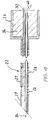
- the entire shank 2 is placed within a clamp 45 as seen in Fig. 5, which has an opening 46 which corresponds to the external dimensions of the shank 2.
- This opening 46 is aligned with a syringe 47 which is used to inject the matrix material under pressure into the passage 13.
- the matrix material 16 fills not only the passage 16 but also the hollow interior of the head 3.
- the issuing of matrix material from the head 3 is an indication that the entire passage 13 is filled and therefore the action of the syringe can be terminated.
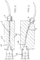
- Fig. 6 illustrates an alternative embodiment where the shank 2 is arcuate or curved and, preferably is curved in such a way as to follow the contours of the heart muscles.
- the probes are utilised by opening the chest wall of the patient, and inserting numbers of the probe shanks 2 into the heart muscle.
- the voltages appearing at the portions 7 (and optionally piercing member 9) are then able to be measured via the connector 5. This enables a determination to be made as to the location of defective tissue.
- RF energy is then able to be applied between either the portions 7 of a probe shank 2, or one or more portions 7 of two or more different shanks 2, or between portions 7 of one or more probes and an external electrode applied to the surface of the body in order to ablate or otherwise change the electrical characteristics of the defective tissue.
- this may be done utilising the piercing member 9 if configured as an electrode.
- the thermocouple wires 11 preferably enable the heat thereby generated to be measured or estimated. Also repeated application of RF energy to the electrodes can, if necessary, be made with temperature and electrical potential measurements being made between the applications of RF energy.
- the needle structure could be made using lithographic techniques in combination with sputtering and deposition techniques to build the needle-like probes in a layer-by-layer process.
Landscapes
- Health & Medical Sciences (AREA)
- Life Sciences & Earth Sciences (AREA)
- Public Health (AREA)
- Engineering & Computer Science (AREA)
- Biomedical Technology (AREA)
- Veterinary Medicine (AREA)
- Animal Behavior & Ethology (AREA)
- General Health & Medical Sciences (AREA)
- Physics & Mathematics (AREA)
- Biophysics (AREA)
- Pathology (AREA)
- Heart & Thoracic Surgery (AREA)
- Medical Informatics (AREA)
- Molecular Biology (AREA)
- Surgery (AREA)
- Radiology & Medical Imaging (AREA)
- Nuclear Medicine, Radiotherapy & Molecular Imaging (AREA)
- Physiology (AREA)
- Cardiology (AREA)
- Surgical Instruments (AREA)
Abstract
Description
- The present invention generally relates to the sensing of electrical potentials in tissue and to the radio frequency (RF) ablation of tissue, and in particular to probes for doing so and methods of constructing such probes.
- It is known that damaged heart muscles can cause abnormal activities of the electrical signals that are generated to create muscle contraction. As a result of this damaged tissue, the heart instead of beating as "normal" can have an increased heartbeat (ventricular tachycardia).
- Hitherto, such cardiac defects have been treated either by means of drugs or by means of a catheter inserted into the heart via a patient's blood passages (e.g., a vein). With drug treatment, the effects are not entirely predictable and often many side effects occur. In general, the treatment with drugs is thought to be only approximately 30 to 35% successful.
- The second treatment involves the insertion of electrodes into the heart via a catheter inserted through a vein. Such a catheter is typically an elongated, cylindrical body made of flexible material that is fitted with two or more electrodes at a distal end. Radio frequency energy is then applied between two electrodes so as to cause ablation. In particular, it is desired, in this way, to remove the defective tissue, or at least change its electrical properties, to prevent re-entry of the electrical signals necessary to cause contraction of the muscle. It has been found difficult to locate correctly the catheter and the necessary electrodes with any precision, partly due to the interior nature of the mechanism of the arrhythmia and also due to the continuous movement of the heart muscles.
- International (PCT) Patent Publication No. WO 92/21278 (PCT/US92/04315) published on 10 December 1992 describes a combination monophasic action potential/ablation catheter and high performance filter system. The catheter probe has a terminal tip portion and an electrode on the tip. A reference electrode is spaced along the tip displaced from the tip for supplying a reference potential signal. An ablating electrode is positioned between the tip and reference electrodes to provide electromagnetic energy. The catheter is described to have a steering mechanism and a structure for holding the tip electrode in perpendicular contact with heart tissue with a positive pressure and to space the reference electrode from the heart.
- It is therefore an object of the present invention to both provide probes and a method of manufacturing same to overcome one or more disadvantages of the prior art.
- In accordance with a first aspect of the invention, there is provided a needle-like probe for use in electrical potential sensing and RF ablation of tissue, comprising: an elongated body with one end adapted for penetration of tissue and having sufficient rigidity to be inserted into the tissue, the elongated body comprising two or more electrodes separated and spaced apart from each other along the elongated body by insulative material; each electrode having at least one electrical conductor coupled to the electrode, the electrode capable of delivering RF energy to the tissue surrounding the electrode and sensing the electrical potential of the tissue.
- Preferably, the two or more electrodes each comprise a metal band incorporated in the elongated body and optionally include a thermal sensing means for measuring the temperature at the interface between the electrode and the tissue. Still further, the elongated body can internally incorporate an elongated rigid member for providing structural stiffening of the probe. The elongated rigid member can be comprised of metal and is rigidly fixed to at least the one end adapted for penetration of the tissue.
- Preferably, the two or more electrodes and the insulative material form a tubular structure and the interior cavity of the tubular structure is filled with matrix material.
- Preferably, the probe comprises at least four electrodes and at least three insulative portions interleaved therewith. Optionally, the elongated body has a substantially arcuate or curved form.
- In accordance with a second aspect of the present invention, there is disclosed a multipolar transmural probe, the probe comprising a needle shaped shank extending from a head, the shank being formed from a plurality of substantially tubular conductive portions, each adjacent pair of which has a substantially tubular insulative member interposed therebetween with the hollow interiors of the portion and members being aligned to form a passageway leading to the head, electrical conductors extending through the passageway to provide an electrically conductive path between each the portion and the head, and stiffening means extending through the passageway and being in force transmitting relationship with the portions and members.
- Preferably, the probe includes at least one thermocouple associated with a corresponding pair of the conductive portions.
- Preferably, the stiffening means comprises a solid steel needle embedded in a flowable, hardenable material (such as epoxy resin) which fills the interior of the passageway not occupied by the stiffening needle and electrical conductors.
- In accordance with a third aspect of the present invention, there is provided a method of manufacturing a multipolar transmural probe, the method comprising the steps of:
- (i) electrically connecting each of a plurality of substantially tubular conductive portions with a corresponding electrical conductor,
- (ii) threading the conductive portions onto a stiffening needle to form a passageway with a substantially tubular insulative member located on the needle between each adjacent pair of conductive portions with the electrical conductors passing through the passageway,
- (iv) clamping the portions and members to retain same in substantially longitudinal axial compression to immobilise same, and
- (v) forcing a flowable hardenable substance into the passageway.
-
- In accordance with a fourth aspect of the invention, there is provided a probe array for use in electrical potential sensing and RF ablation of tissue, the array comprising a plurality of needle-like probes, wherein each of the needle-like probes comprises: an elongated shank with one end adapted for piercing tissue and having sufficient rigidity to be inserted into the tissue, the shank comprising two or more electrodes displaced from each other along the shank by insulative material; each electrode having at least one electrical conductor coupled to the electrode, the electrode capable of delivering RF energy to the tissue surrounding the electrode and sensing the electrical potential of the tissue.
- Preferably, the two or more electrodes each comprise a metal band forming part of the elongated shank and optionally include a thermocouple for measuring the temperature at the interface between the electrode and the tissue.
- Preferably, the two or more electrodes and corresponding insulative sections form a tubular structure through which the at least one electrical conductor of each electrode passes in each probe of the array. Further, the elongated rigid member of each probe is optionally comprised of metal and is rigidly fixed to at least the one end adapted for piercing the tissue. Still further, the interior cavity of the tubular structure is filled with matrix material.
- Embodiments of the present invention will now be described with reference to the drawings in which:
- Fig. 1 is a schematic perspective view of the entire probe of the first embodiment,
- Fig. 2 is a truncated longitudinal cross-section through the shank and head of the probe of Fig. 1,
- Fig. 3 is a transverse cross-sectional view taken along the line 3-3 of Fig. 2,
- Fig. 4 is a view similar to Fig. 2 but illustrating the probe of the second embodiment,
- Fig. 5 is a cross-sectional view through a clamp and syringe used in the manufacture of the probe of either Figs. 2 or 4, and
- Fig. 6 is a view similar to Fig. 5 but illustrating the manufacture of a third embodiment having a curved shank.
-
- The present invention is concerned with a different solution to those proposed using a catheter that passes through a passageway (e.g. a vein) of the patient and hence into the heart. Instead, open-chest surgery (thoracotomy) is undertaken and electrodes are able to be inserted directly into the myocardium, or heart muscle, from the exterior of the heart. The electrical probes can be used to detect muscle that creates irregular heartbeats (arrhythmia). Upwards of approximately 30 to 70 of such probes, each having one or more electrodes, can be required. Other numbers of probes (and likewise electrodes) can be used without departing from the scope of the invention.
- If the electrical potentials experienced by the electrodes of such probes are measured, an algorithm can be applied to the detected electrical signals that enables detection of those muscles creating the arrhythmia. Once those muscles have been detected, the application of RF energy to electrodes straddling the muscle can be used to disable the defective tissue. For this procedure to be carried out, it is necessary to have a needle-like probe that is able to be inserted into the myocardium and which can preferably both detect the small electrical potentials generated by the patient to contract the muscle, and also deliver the RF energy. While the embodiments of the invention are described with reference to heart muscle (myocardium), it will be apparent to a person skilled in the art that the present invention has broader application to other types of tissue without departing from the scope of the invention.
- During ablation, it is desirable to closely regulate the amount of heart muscle destroyed. Monitoring of the temperature at the interface between the electrode and the heart muscle and adjusting the amount of radio frequency energy delivery has been found to be the best way of doing this. By incorporation of one or more thermocouples within the electrodes of the probes, such monitoring becomes possible. Alternatively, a thermistor or other temperature sensing transducer can be employed in each electrode to measure the temperature. A similar problem arises in the field of neurophysiology and the arrangements of the present invention find application in the RF ablation of tumours, or other abnormalities, of the brain. The embodiments of the invention will now be described in detail with reference to Figs. 1 to 6.
- As seen in Fig. 1, the probe 1 takes the form of a
shank 2 which extends from ahead 3 that is connected by means of acable 4 to an electrical connector 5. The electrical connector 5 of Fig. 1 is illustrated as a cylindrically shaped, socket connector with a number of pins projecting within the inner metal sleeve of the connector 5. It will be apparent to a person skilled in the art that other types of connectors having different configurations can be practiced without departing from the scope of the invention. Theshank 2 is formed from a series of conductive portions 7 which are separated by coaxially alignedinsulative members 8. Both the portions 7 andmembers 8 are tubular, and thus theshank 2 has a hollow interior. A piercingmember 9 at the distal end of theshank 2 is adapted for penetration of tissue. Preferably, themember 9 is made of metal and has a bevelled edge for penetrating or piercing tissue. Optionally, themember 9 can be used as an electrode and may have a thermocouple. It will be apparent to a person skilled in the art that modifications to themember 9 and/or theshank 2 can be made without departing from the scope and spirit of the invention. The piercingmember 9 may also be separated from a portion 7 by aninsulative member 8. - As best seen in Fig. 2, each of the conductive portions 7 preferably has two separate insulated electrical conductors spot welded thereto. One of these
conductors 10 is used to provide electrical connection to the conductive portion itself whilst theother conductor 11 is used in the creation of a thermocouple. Thus, whilst thewire 10 is preferably formed from stainless steel and is welded to the stainless steel conductive portion 7, theother wire 11 is formed from a material such as nickel. Thethermocouple wires 11 enable the temperature of the myocardium to be measured. - The hollow interiors of the portions 7,
members 8, and piercingmember 9 constitute apassageway 13 within which is located a TEFLON (trademark) coatedstainless steel needle 14 which considerably stiffens theshank 2. A like, suitably stiff, elongated object may also be used instead of a stainless steel needle. Themembers 8 are preferably fabricated from TEFLON. As best indicated in Fig. 3, theneedle 14 andwires matrix 16 formed from a flowable, hardenable substance such as epoxy resin, or the like. Thus, all the materials used are preferably biocompatable. - With reference to Fig. 3, the preferred dimensions for the
shank 2 are as follows:Outer diameter 0.8 mm, Inner diameter of portion 7 and members 80.66 mm, Length of portions 7 and members 81.5 mm, Outer diameter of needle 140.35 mm. members 8 is increased to 3.0 mm. It is also not necessary for the portions 7 andmembers 8 to each be the same length. The piercingmember 9 can have substantially the same dimensions as that of portion 7 andmember 8. However, it will be apparent to a person skilled in the art that modifications can be made to the piercingmember 9 without departing from the scope of the invention. - In yet another embodiment being a septal probe, the shank has the following dimensions:
Outer diameter 1.1 mm, Inner diameter of portion 7 and member 80.9 mm, Length of portion 7 2.0 mm, Length of member 82.5 mm, Outer diameter of needle 140.4 mm. - It will be apparent to a person skilled in the art that changes can be made to the dimensions of the probe and its components without departing from the scope of the invention. Further, the number of electrodes and the dimensions of the electrodes can be programmed, or varied, to suit particular applications. Likewise, the overall structure of the needle-like probe can be programmed including variations to the dimensions of the insulative material. Thus, for example, the overall length of the
shank 2 can be doubled to provide twice as many electrodes as set forth above in the preferred embodiment. - Fig. 4 illustrates an alternative arrangement in which all reference numerals for like elements are increased by twenty (20). The
shank 22 andhead 23 are essentially as before. Onlyconductive wires 30 are provided and theneedle 34 is provided with akink 40 within thehead 23 to provide a stronger anchor. In addition, the leading end of theneedle 34 has its TEFLON coating stripped away and is electrically resistance welded to the leadingconductive portion 29, which is adapted to penetrate tissue. As indicated by means of broken lines in Fig. 4, this welding step takes place preferably prior to the trimming or cutting of the leadingconductive portion 29 which is thereby sharpened in order to provide a sharp point to theshank 22. The above description of piercingmember 9 applies equally to leading conductive portion or piercingmember 29. - After assembly of the portions 7,
members 8, piercingmember 9,wires needle 14, theentire shank 2 is placed within aclamp 45 as seen in Fig. 5, which has an opening 46 which corresponds to the external dimensions of theshank 2. This opening 46 is aligned with a syringe 47 which is used to inject the matrix material under pressure into thepassage 13. Thematrix material 16 fills not only thepassage 16 but also the hollow interior of thehead 3. The issuing of matrix material from thehead 3 is an indication that theentire passage 13 is filled and therefore the action of the syringe can be terminated. These steps may be modified to suit individual requirements without departing from the scope of the invention. - Fig. 6 illustrates an alternative embodiment where the
shank 2 is arcuate or curved and, preferably is curved in such a way as to follow the contours of the heart muscles. - The probes are utilised by opening the chest wall of the patient, and inserting numbers of the
probe shanks 2 into the heart muscle. The voltages appearing at the portions 7 (and optionally piercing member 9) are then able to be measured via the connector 5. This enables a determination to be made as to the location of defective tissue. RF energy is then able to be applied between either the portions 7 of aprobe shank 2, or one or more portions 7 of two or moredifferent shanks 2, or between portions 7 of one or more probes and an external electrode applied to the surface of the body in order to ablate or otherwise change the electrical characteristics of the defective tissue. Alternatively, this may be done utilising the piercingmember 9 if configured as an electrode. Thethermocouple wires 11 preferably enable the heat thereby generated to be measured or estimated. Also repeated application of RF energy to the electrodes can, if necessary, be made with temperature and electrical potential measurements being made between the applications of RF energy. - It will be apparent to a person skilled in the art that modifications to the structure and construction of the probe can be practiced without departing from the scope of the invention. For example, the needle structure could be made using lithographic techniques in combination with sputtering and deposition techniques to build the needle-like probes in a layer-by-layer process.
- The foregoing describes only some embodiments of the present invention and modifications, obvious to those skilled in the art, can be made thereto without departing from the scope of the present invention. For example, although the above description is made with reference to humans, the present invention is equally applicable to other mammals such as racehorses or other applications in industrial environments.
Claims (16)
- A probe (1) for use in electrical potential sensing and RF ablation of tissue comprising:characterised by each electrode (7, 27) being capable of delivering RF energy to said tissue surrounding said electrode (7, 27) and sensing said electrical potential of said tissue, and the interior cavity of said tubular structure (2, 22) being filled with matrix material (16).an elongated body (2, 22) comprising two or more electrodes (7, 27) separated and spaced apart from each other along said elongated body (2, 22) by insulative material (8, 28), wherein said two or more electrodes (7, 27) and said insulative material (8, 28) form a tubular structure (2, 22);each electrode (7, 27) having at least one electrical conductor (10) coupled to said electrode (7, 27),
- The probe according to claim 1, characterised in that said two or more electrodes (7, 27) each comprise a metal band incorporated in said elongated body (2, 22).
- The probe according to claim 1, characterised in that said elongated body (2, 22) internally incorporates an elongated rigid member (14) for providing structural stiffening of said probe (1).
- The probe according to claim 3, characterised in that said elongated rigid member (14) is comprised of metal or rigid material and is rigidly fixed to at least one end (9, 29) adapted for penetration of said tissue.
- The probe according to claim 1 characterised in that said probe (1) comprises at least four electrodes (7, 27) and at least three insulative portions (8, 28) interleaved therewith.
- The probe according to claim 1 characterised in that said elongated body (2) has an arcuate or curved form.
- The probe according to claim 1, characterised in that said elongated body is a needle-shaped shank (2, 22) extending from a head (3, 23), and said electrodes are tubular conductive portions (7, 27), said insulative material (8, 28) comprising tubular insulative members (8, 28), each adjacent pair of portions (7, 27) has a tubular insulative member (8, 28) interposed therebetween with hollow interiors of said portions (7, 27) and members (8, 28) being aligned to form a passageway (13) leading to said head (3, 23), electrical conductors (10, 11, 30) extending through said passageway (13) to provide an electrically conductive path between each said portion (7, 27) and said head (3, 23), and
stiffening means (14) extending through said passageway (13) and being in force transmitting relationship with said portions (7, 27) and members (8, 28), said matrix material (16) comprising a flowable hardenable material, wherein the stiffening means (14) comprises a solid steel needle embedded in said flowable hardenable material which fills the interior of the passageway (13) not occupied by the stiffening needle and electrical conductors (10, 11, 30). - The probe according to claim 7 characterised by further comprising at least one thermocouple (10) associated with a corresponding pair of said conductive portions (7, 27).
- The probe according to claim 7 characterised in that the flowable, hardenable material (16) comprises an epoxy resin.
- The probe according to any one of claims 1 to 9, characterised in that each electrode (7, 27) comprises means for measuring the temperature (11) at the interface between said electrode (7, 27) and said tissue.
- The probe according to claim 1, characterised in that said elongated body (2, 22) is an elongated shank internally incorporating an elongated rigid member (14), said elongated rigid member (14) being comprised of metal and is rigidly fixed to at least a first electrode forming one end (9, 29) adapted for piercing said tissue.
- The probe according to any one of claims 1 to 11, characterised in that said probe (1) is needle-like.
- The probe according to any one of claims 1 to 11, characterised in that said probe (1) is a multipolar transmural probe.
- The probe according to any one of claims 1 to 13, characterised in that said elongated body has one end (9, 29) adapted for penetration of tissue and has sufficient rigidity to be inserted into said tissue.
- A probe array for use in electrical potential sensing and RF ablation of tissue, said array characterised by comprising a plurality of probes in accordance with any one of claims 1 to 14.
- A method of manufacturing the probe of claim 1, said method characterised by comprising the steps of:electrically connecting each of a plurality of tubular conductive portions (7, 27) with a corresponding electrical conductor (10, 11, 30);threading the conductive portions (7, 27) onto a stiffening needle (14) to form a passageway (13) with a tubular insulative member (8, 28) located on said needle (14) between each adjacent pair of conductive portions (7, 27) with said electrical conductors (10, 11, 30) passing through said passageway (13);clamping said portions (7, 27) and members to retain same in longitudinal axial compression to immobilise same; andforcing a flowable hardenable substance (16) into said passageway (13).
Applications Claiming Priority (5)
| Application Number | Priority Date | Filing Date | Title |
|---|---|---|---|
| AUPN4874A AUPN487495A0 (en) | 1995-08-18 | 1995-08-18 | A multipolar transmural probe |
| AUPN4874/95 | 1995-08-18 | ||
| AUPN487495 | 1995-08-18 | ||
| PCT/AU1996/000489 WO1997006727A1 (en) | 1995-08-18 | 1996-08-02 | A multipolar transmural probe |
| US09/031,861 US6096035A (en) | 1995-08-18 | 1998-02-27 | Multipolar transmural probe |
Publications (3)
| Publication Number | Publication Date |
|---|---|
| EP0850015A1 EP0850015A1 (en) | 1998-07-01 |
| EP0850015A4 EP0850015A4 (en) | 1999-02-03 |
| EP0850015B1 true EP0850015B1 (en) | 2004-02-18 |
Family
ID=25645006
Family Applications (1)
| Application Number | Title | Priority Date | Filing Date |
|---|---|---|---|
| EP96925601A Expired - Lifetime EP0850015B1 (en) | 1995-08-18 | 1996-08-02 | A multipolar transmural probe |
Country Status (4)
| Country | Link |
|---|---|
| US (1) | US6096035A (en) |
| EP (1) | EP0850015B1 (en) |
| AU (1) | AUPN487495A0 (en) |
| WO (1) | WO1997006727A1 (en) |
Cited By (2)
| Publication number | Priority date | Publication date | Assignee | Title |
|---|---|---|---|---|
| KR101380807B1 (en) * | 2012-07-27 | 2014-04-04 | 광주과학기술원 | Syringe capable of temperature measurement and manufacturing method thereof |
| FR3130545A1 (en) * | 2021-12-17 | 2023-06-23 | Commissariat A L'energie Atomique Et Aux Energies Alternatives | Device for measuring the electrical and thermal activity of a living being |
Families Citing this family (104)
| Publication number | Priority date | Publication date | Assignee | Title |
|---|---|---|---|---|
| US6161543A (en) | 1993-02-22 | 2000-12-19 | Epicor, Inc. | Methods of epicardial ablation for creating a lesion around the pulmonary veins |
| AUPN957296A0 (en) | 1996-04-30 | 1996-05-23 | Cardiac Crc Nominees Pty Limited | A system for simultaneous unipolar multi-electrode ablation |
| US6840936B2 (en) | 1996-10-22 | 2005-01-11 | Epicor Medical, Inc. | Methods and devices for ablation |
| US6719755B2 (en) | 1996-10-22 | 2004-04-13 | Epicor Medical, Inc. | Methods and devices for ablation |
| US7052493B2 (en) | 1996-10-22 | 2006-05-30 | Epicor Medical, Inc. | Methods and devices for ablation |
| US6311692B1 (en) | 1996-10-22 | 2001-11-06 | Epicor, Inc. | Apparatus and method for diagnosis and therapy of electrophysiological disease |
| US6237605B1 (en) | 1996-10-22 | 2001-05-29 | Epicor, Inc. | Methods of epicardial ablation |
| US9155496B2 (en) | 1997-03-04 | 2015-10-13 | Dexcom, Inc. | Low oxygen in vivo analyte sensor |
| AUPO820897A0 (en) * | 1997-07-24 | 1997-08-14 | Cardiac Crc Nominees Pty Limited | An intraoperative endocardial and epicardial ablation probe |
| US6175752B1 (en) | 1998-04-30 | 2001-01-16 | Therasense, Inc. | Analyte monitoring device and methods of use |
| US8974386B2 (en) | 1998-04-30 | 2015-03-10 | Abbott Diabetes Care Inc. | Analyte monitoring device and methods of use |
| US8480580B2 (en) | 1998-04-30 | 2013-07-09 | Abbott Diabetes Care Inc. | Analyte monitoring device and methods of use |
| US8346337B2 (en) | 1998-04-30 | 2013-01-01 | Abbott Diabetes Care Inc. | Analyte monitoring device and methods of use |
| US8465425B2 (en) | 1998-04-30 | 2013-06-18 | Abbott Diabetes Care Inc. | Analyte monitoring device and methods of use |
| US9066695B2 (en) | 1998-04-30 | 2015-06-30 | Abbott Diabetes Care Inc. | Analyte monitoring device and methods of use |
| US8688188B2 (en) | 1998-04-30 | 2014-04-01 | Abbott Diabetes Care Inc. | Analyte monitoring device and methods of use |
| US6527767B2 (en) | 1998-05-20 | 2003-03-04 | New England Medical Center | Cardiac ablation system and method for treatment of cardiac arrhythmias and transmyocardial revascularization |
| AU2001249874A1 (en) | 2000-04-27 | 2001-11-12 | Medtronic, Inc. | System and method for assessing transmurality of ablation lesions |
| US6475179B1 (en) | 2000-11-10 | 2002-11-05 | New England Medical Center | Tissue folding device for tissue ablation, and method thereof |
| US6560471B1 (en) | 2001-01-02 | 2003-05-06 | Therasense, Inc. | Analyte monitoring device and methods of use |
| US6793632B2 (en) * | 2001-06-12 | 2004-09-21 | Lifescan, Inc. | Percutaneous biological fluid constituent sampling and measurement devices and methods |
| US20030032874A1 (en) | 2001-07-27 | 2003-02-13 | Dexcom, Inc. | Sensor head for use with implantable devices |
| US10022078B2 (en) | 2004-07-13 | 2018-07-17 | Dexcom, Inc. | Analyte sensor |
| ITBS20020040U1 (en) * | 2002-03-20 | 2003-09-22 | Fogazzi Di Venturelli Andrea & | CATHETER WITH AN ELECTRODE FOR TREATMENT OF TUMORS BY RADIOFREQUENCY-INDUCED HYPERTHERMIA |
| US7686802B2 (en) * | 2003-03-28 | 2010-03-30 | C.R. Bard, Inc. | Junction of catheter tip and electrode |
| WO2005012873A2 (en) | 2003-07-25 | 2005-02-10 | Dexcom, Inc. | Electrode systems for electrochemical sensors |
| US9135402B2 (en) | 2007-12-17 | 2015-09-15 | Dexcom, Inc. | Systems and methods for processing sensor data |
| US20080119703A1 (en) | 2006-10-04 | 2008-05-22 | Mark Brister | Analyte sensor |
| US8275437B2 (en) | 2003-08-01 | 2012-09-25 | Dexcom, Inc. | Transcutaneous analyte sensor |
| US20190357827A1 (en) | 2003-08-01 | 2019-11-28 | Dexcom, Inc. | Analyte sensor |
| US7591801B2 (en) | 2004-02-26 | 2009-09-22 | Dexcom, Inc. | Integrated delivery device for continuous glucose sensor |
| US8886273B2 (en) | 2003-08-01 | 2014-11-11 | Dexcom, Inc. | Analyte sensor |
| US7774145B2 (en) | 2003-08-01 | 2010-08-10 | Dexcom, Inc. | Transcutaneous analyte sensor |
| US8626257B2 (en) | 2003-08-01 | 2014-01-07 | Dexcom, Inc. | Analyte sensor |
| US7920906B2 (en) | 2005-03-10 | 2011-04-05 | Dexcom, Inc. | System and methods for processing analyte sensor data for sensor calibration |
| US8615282B2 (en) | 2004-07-13 | 2013-12-24 | Dexcom, Inc. | Analyte sensor |
| US9247900B2 (en) | 2004-07-13 | 2016-02-02 | Dexcom, Inc. | Analyte sensor |
| WO2005051170A2 (en) | 2003-11-19 | 2005-06-09 | Dexcom, Inc. | Integrated receiver for continuous analyte sensor |
| US8364231B2 (en) | 2006-10-04 | 2013-01-29 | Dexcom, Inc. | Analyte sensor |
| US11633133B2 (en) | 2003-12-05 | 2023-04-25 | Dexcom, Inc. | Dual electrode system for a continuous analyte sensor |
| DE602004029092D1 (en) | 2003-12-05 | 2010-10-21 | Dexcom Inc | CALIBRATION METHODS FOR A CONTINUOUSLY WORKING ANALYTIC SENSOR |
| US8423114B2 (en) | 2006-10-04 | 2013-04-16 | Dexcom, Inc. | Dual electrode system for a continuous analyte sensor |
| EP2316331B1 (en) | 2003-12-09 | 2016-06-29 | Dexcom, Inc. | Signal processing for continuous analyte sensor |
| US8808228B2 (en) | 2004-02-26 | 2014-08-19 | Dexcom, Inc. | Integrated medicament delivery device for use with continuous analyte sensor |
| US8792955B2 (en) | 2004-05-03 | 2014-07-29 | Dexcom, Inc. | Transcutaneous analyte sensor |
| US20050283148A1 (en) * | 2004-06-17 | 2005-12-22 | Janssen William M | Ablation apparatus and system to limit nerve conduction |
| US8565848B2 (en) | 2004-07-13 | 2013-10-22 | Dexcom, Inc. | Transcutaneous analyte sensor |
| US8452368B2 (en) | 2004-07-13 | 2013-05-28 | Dexcom, Inc. | Transcutaneous analyte sensor |
| US7946984B2 (en) | 2004-07-13 | 2011-05-24 | Dexcom, Inc. | Transcutaneous analyte sensor |
| US20090076360A1 (en) | 2007-09-13 | 2009-03-19 | Dexcom, Inc. | Transcutaneous analyte sensor |
| US8932208B2 (en) | 2005-05-26 | 2015-01-13 | Maquet Cardiovascular Llc | Apparatus and methods for performing minimally-invasive surgical procedures |
| US9757061B2 (en) | 2006-01-17 | 2017-09-12 | Dexcom, Inc. | Low oxygen in vivo analyte sensor |
| US8075556B2 (en) * | 2006-05-23 | 2011-12-13 | Andres Betts | High frequency epidural neuromodulation catheter for effectuating RF treatment in spinal canal and method of using same |
| US8562558B2 (en) | 2007-06-08 | 2013-10-22 | Dexcom, Inc. | Integrated medicament delivery device for use with continuous analyte sensor |
| US7974704B2 (en) | 2007-08-22 | 2011-07-05 | Medtronic, Inc. | Lead body constructions for implantable medical electrical leads |
| WO2009045265A1 (en) | 2007-10-05 | 2009-04-09 | Maquet Cardiovascular, Llc | Devices and methods for minimally-invasive surgical procedures |
| EP4159114B1 (en) | 2007-10-09 | 2024-04-10 | DexCom, Inc. | Integrated insulin delivery system with continuous glucose sensor |
| US8417312B2 (en) | 2007-10-25 | 2013-04-09 | Dexcom, Inc. | Systems and methods for processing sensor data |
| US8290559B2 (en) | 2007-12-17 | 2012-10-16 | Dexcom, Inc. | Systems and methods for processing sensor data |
| EP2252196A4 (en) | 2008-02-21 | 2013-05-15 | Dexcom Inc | Systems and methods for processing, transmitting and displaying sensor data |
| US8396528B2 (en) | 2008-03-25 | 2013-03-12 | Dexcom, Inc. | Analyte sensor |
| US9867652B2 (en) | 2008-04-29 | 2018-01-16 | Virginia Tech Intellectual Properties, Inc. | Irreversible electroporation using tissue vasculature to treat aberrant cell masses or create tissue scaffolds |
| US8992517B2 (en) | 2008-04-29 | 2015-03-31 | Virginia Tech Intellectual Properties Inc. | Irreversible electroporation to treat aberrant cell masses |
| US10272178B2 (en) | 2008-04-29 | 2019-04-30 | Virginia Tech Intellectual Properties Inc. | Methods for blood-brain barrier disruption using electrical energy |
| US10238447B2 (en) | 2008-04-29 | 2019-03-26 | Virginia Tech Intellectual Properties, Inc. | System and method for ablating a tissue site by electroporation with real-time monitoring of treatment progress |
| US10702326B2 (en) | 2011-07-15 | 2020-07-07 | Virginia Tech Intellectual Properties, Inc. | Device and method for electroporation based treatment of stenosis of a tubular body part |
| US12697172B2 (en) | 2008-04-29 | 2026-08-04 | Virginia Tech Intellectual Properties, Inc. | System and method for estimating a treatment volume for administering electrical-energy based therapies |
| US9198733B2 (en) | 2008-04-29 | 2015-12-01 | Virginia Tech Intellectual Properties, Inc. | Treatment planning for electroporation-based therapies |
| US11254926B2 (en) | 2008-04-29 | 2022-02-22 | Virginia Tech Intellectual Properties, Inc. | Devices and methods for high frequency electroporation |
| US10117707B2 (en) | 2008-04-29 | 2018-11-06 | Virginia Tech Intellectual Properties, Inc. | System and method for estimating tissue heating of a target ablation zone for electrical-energy based therapies |
| US10245098B2 (en) | 2008-04-29 | 2019-04-02 | Virginia Tech Intellectual Properties, Inc. | Acute blood-brain barrier disruption using electrical energy based therapy |
| US10448989B2 (en) | 2009-04-09 | 2019-10-22 | Virginia Tech Intellectual Properties, Inc. | High-frequency electroporation for cancer therapy |
| US11272979B2 (en) | 2008-04-29 | 2022-03-15 | Virginia Tech Intellectual Properties, Inc. | System and method for estimating tissue heating of a target ablation zone for electrical-energy based therapies |
| US9283051B2 (en) | 2008-04-29 | 2016-03-15 | Virginia Tech Intellectual Properties, Inc. | System and method for estimating a treatment volume for administering electrical-energy based therapies |
| US8560039B2 (en) | 2008-09-19 | 2013-10-15 | Dexcom, Inc. | Particle-containing membrane and particulate electrode for analyte sensors |
| US8632534B2 (en) | 2009-04-03 | 2014-01-21 | Angiodynamics, Inc. | Irreversible electroporation (IRE) for congestive obstructive pulmonary disease (COPD) |
| US11382681B2 (en) | 2009-04-09 | 2022-07-12 | Virginia Tech Intellectual Properties, Inc. | Device and methods for delivery of high frequency electrical pulses for non-thermal ablation |
| US11638603B2 (en) | 2009-04-09 | 2023-05-02 | Virginia Tech Intellectual Properties, Inc. | Selective modulation of intracellular effects of cells using pulsed electric fields |
| US8903488B2 (en) | 2009-05-28 | 2014-12-02 | Angiodynamics, Inc. | System and method for synchronizing energy delivery to the cardiac rhythm |
| US9895189B2 (en) | 2009-06-19 | 2018-02-20 | Angiodynamics, Inc. | Methods of sterilization and treating infection using irreversible electroporation |
| WO2011041463A2 (en) | 2009-09-30 | 2011-04-07 | Dexcom, Inc. | Transcutaneous analyte sensor |
| WO2012051433A2 (en) | 2010-10-13 | 2012-04-19 | Angiodynamics, Inc. | System and method for electrically ablating tissue of a patient |
| US20120265036A1 (en) | 2011-04-15 | 2012-10-18 | Dexcom, Inc. | Advanced analyte sensor calibration and error detection |
| US9078665B2 (en) | 2011-09-28 | 2015-07-14 | Angiodynamics, Inc. | Multiple treatment zone ablation probe |
| US9414881B2 (en) | 2012-02-08 | 2016-08-16 | Angiodynamics, Inc. | System and method for increasing a target zone for electrical ablation |
| EP3143124B1 (en) | 2014-05-12 | 2025-01-22 | Virginia Tech Intellectual Properties, Inc. | Selective modulation of intracellular effects of cells using pulsed electric fields |
| US12114911B2 (en) | 2014-08-28 | 2024-10-15 | Angiodynamics, Inc. | System and method for ablating a tissue site by electroporation with real-time pulse monitoring |
| WO2016100325A1 (en) | 2014-12-15 | 2016-06-23 | Virginia Tech Intellectual Properties, Inc. | Devices, systems, and methods for real-time monitoring of electrophysical effects during tissue treatment |
| US9113912B1 (en) | 2015-01-21 | 2015-08-25 | Serene Medical, Inc. | Systems and devices to identify and limit nerve conduction |
| US9119628B1 (en) | 2015-01-21 | 2015-09-01 | Serene Medical, Inc. | Systems and devices to identify and limit nerve conduction |
| US10905492B2 (en) | 2016-11-17 | 2021-02-02 | Angiodynamics, Inc. | Techniques for irreversible electroporation using a single-pole tine-style internal device communicating with an external surface electrode |
| CN111246797B (en) | 2017-10-24 | 2025-09-09 | 德克斯康公司 | Pre-attached analyte sensor |
| US11331022B2 (en) | 2017-10-24 | 2022-05-17 | Dexcom, Inc. | Pre-connected analyte sensors |
| US11607537B2 (en) | 2017-12-05 | 2023-03-21 | Virginia Tech Intellectual Properties, Inc. | Method for treating neurological disorders, including tumors, with electroporation |
| US11103308B2 (en) | 2017-12-11 | 2021-08-31 | Covidien Lp | Reusable transmission network for dividing energy and monitoring signals between surgical devices |
| US12390262B2 (en) | 2018-03-13 | 2025-08-19 | Virginia Tech Intellectual Properties, Inc. | Treatment planning system for immunotherapy enhancement via non-thermal ablation |
| US11311329B2 (en) | 2018-03-13 | 2022-04-26 | Virginia Tech Intellectual Properties, Inc. | Treatment planning for immunotherapy based treatments using non-thermal ablation techniques |
| US11925405B2 (en) | 2018-03-13 | 2024-03-12 | Virginia Tech Intellectual Properties, Inc. | Treatment planning system for immunotherapy enhancement via non-thermal ablation |
| USD863386S1 (en) | 2018-06-06 | 2019-10-15 | Kennametal Inc. | Ribbed cutting insert |
| US11950835B2 (en) | 2019-06-28 | 2024-04-09 | Virginia Tech Intellectual Properties, Inc. | Cycled pulsing to mitigate thermal damage for multi-electrode irreversible electroporation therapy |
| US12214189B2 (en) | 2019-07-24 | 2025-02-04 | Virginia Tech Intellectual Properties, Inc. | Fourier analysis spectroscopy for monitoring tissue impedance changes and treatment outcome during electroporation-based-therapies |
| CA3163236A1 (en) * | 2019-11-27 | 2021-06-03 | Blossom Innovations, LLC | Devices, systems and methods for tissue analysis, location determination and tissue ablation |
| US12485279B2 (en) | 2020-11-25 | 2025-12-02 | Virginia Tech Intellectual Properties, Inc. | Methods for modulating temporal infrastructure of pulsed electric fields |
| WO2023107650A2 (en) * | 2021-12-10 | 2023-06-15 | Kellogg Brown & Root Llc | Thermally coupled distillation scheme for purification of cumene |
Family Cites Families (14)
| Publication number | Priority date | Publication date | Assignee | Title |
|---|---|---|---|---|
| US4630617A (en) * | 1980-10-09 | 1986-12-23 | American Cyanamid Company | Heart pacer lead wire with pull-away needle |
| US5370675A (en) * | 1992-08-12 | 1994-12-06 | Vidamed, Inc. | Medical probe device and method |
| US4966597A (en) * | 1988-11-04 | 1990-10-30 | Cosman Eric R | Thermometric cardiac tissue ablation electrode with ultra-sensitive temperature detection |
| US5232948A (en) * | 1990-09-10 | 1993-08-03 | Rhone-Poulenc Rorer Pharmaceuticals Inc. | Substituted monocyclic aryl compounds exhibiting selective leukotriene b4 antagonist activity |
| CA2109793A1 (en) * | 1991-05-24 | 1992-12-10 | Stuart D. Edwards | Combination monophasic action potential/ablation catheter and high-performance filter system |
| DE69233091T2 (en) * | 1991-11-08 | 2004-05-06 | Boston Scientific Ltd., St. Michael | ABLATION ELECTRODE WITH INSULATED TEMPERATURE MEASURING ELEMENT |
| US5324098A (en) * | 1992-12-17 | 1994-06-28 | Kennametal Inc. | Cutting tool having hard tip with lobes |
| US5599345A (en) * | 1993-11-08 | 1997-02-04 | Zomed International, Inc. | RF treatment apparatus |
| US5472441A (en) * | 1993-11-08 | 1995-12-05 | Zomed International | Device for treating cancer and non-malignant tumors and methods |
| US5407607A (en) * | 1993-11-09 | 1995-04-18 | Mix; Thomas W. | Structured packing elements |
| US5487385A (en) * | 1993-12-03 | 1996-01-30 | Avitall; Boaz | Atrial mapping and ablation catheter system |
| US5524337A (en) * | 1994-09-21 | 1996-06-11 | Ep Technologies, Inc. | Method of securing ring electrodes onto catheter |
| WO1996010950A1 (en) * | 1994-10-07 | 1996-04-18 | Cordis Webster, Inc. | Combined radiofrequency and high voltage pulse catheter ablation |
| US5849028A (en) * | 1997-05-16 | 1998-12-15 | Irvine Biomedical, Inc. | Catheter and method for radiofrequency ablation of cardiac tissue |
-
1995
- 1995-08-18 AU AUPN4874A patent/AUPN487495A0/en not_active Abandoned
-
1996
- 1996-08-02 EP EP96925601A patent/EP0850015B1/en not_active Expired - Lifetime
- 1996-08-02 WO PCT/AU1996/000489 patent/WO1997006727A1/en not_active Ceased
-
1998
- 1998-02-27 US US09/031,861 patent/US6096035A/en not_active Expired - Lifetime
Cited By (3)
| Publication number | Priority date | Publication date | Assignee | Title |
|---|---|---|---|---|
| KR101380807B1 (en) * | 2012-07-27 | 2014-04-04 | 광주과학기술원 | Syringe capable of temperature measurement and manufacturing method thereof |
| US9028450B2 (en) | 2012-07-27 | 2015-05-12 | Gwangju Institute Of Science And Technology | Syringe capable of measuring temperature of a patient body and method of manufacturing the same |
| FR3130545A1 (en) * | 2021-12-17 | 2023-06-23 | Commissariat A L'energie Atomique Et Aux Energies Alternatives | Device for measuring the electrical and thermal activity of a living being |
Also Published As
| Publication number | Publication date |
|---|---|
| WO1997006727A1 (en) | 1997-02-27 |
| EP0850015A1 (en) | 1998-07-01 |
| US6096035A (en) | 2000-08-01 |
| EP0850015A4 (en) | 1999-02-03 |
| AUPN487495A0 (en) | 1995-09-14 |
Similar Documents
| Publication | Publication Date | Title |
|---|---|---|
| US6096035A (en) | Multipolar transmural probe | |
| EP0868146B1 (en) | Split tip electrode catheter | |
| US5517989A (en) | Guidewire assembly | |
| US5951471A (en) | Catheter-based coronary sinus mapping and ablation | |
| US6064905A (en) | Multi-element tip electrode mapping catheter | |
| US6099524A (en) | Electrophysiological mapping and ablation catheter and method | |
| CA2223904C (en) | Catheter with a spirally wound flat ribbon electrode | |
| CA2250875C (en) | Electrophysiology catheter with a bullseye electrode | |
| US6308090B1 (en) | Devices and methods for coronary sinus mapping | |
| DE69419172T2 (en) | ELECTRODE ARRANGEMENT FOR CATHETER | |
| US6029091A (en) | Catheter system having lattice electrodes | |
| US6663573B2 (en) | Bipolar mapping of intracardiac potentials using recessed electrodes | |
| US5891138A (en) | Catheter system having parallel electrodes | |
| JP2021098015A (en) | Expandable assembly catheter | |
| EP3790484B1 (en) | Intravascular catheter tip electrode assemblies | |
| EP3040043A1 (en) | Catheter with irrigated tip electrode with porous substrate and high density surface micro-electrodes | |
| US6134463A (en) | Electrophysiology catheter with a bullseye electrode | |
| EP4225183A1 (en) | Spring-loaded catheter for an electrophysiology (ep) study and irreversible electroporation within the heart | |
| EP3363355A1 (en) | Electrophysiologic device construction | |
| EP3932354B1 (en) | Electroporation with cooling | |
| AU701125B2 (en) | A multipolar transmural probe | |
| HK1012221A (en) | Improved electrophysiological mapping and ablation catheter and method |
Legal Events
| Date | Code | Title | Description |
|---|---|---|---|
| PUAI | Public reference made under article 153(3) epc to a published international application that has entered the european phase |
Free format text: ORIGINAL CODE: 0009012 |
|
| 17P | Request for examination filed |
Effective date: 19980318 |
|
| AK | Designated contracting states |
Kind code of ref document: A1 Designated state(s): DE FR GB IT |
|
| A4 | Supplementary search report drawn up and despatched |
Effective date: 19981221 |
|
| AK | Designated contracting states |
Kind code of ref document: A4 Designated state(s): DE FR GB IT |
|
| RAP1 | Party data changed (applicant data changed or rights of an application transferred) |
Owner name: WESTERN SYDNEY AREA HEALTH SERVICE |
|
| 17Q | First examination report despatched |
Effective date: 20021125 |
|
| GRAP | Despatch of communication of intention to grant a patent |
Free format text: ORIGINAL CODE: EPIDOSNIGR1 |
|
| GRAP | Despatch of communication of intention to grant a patent |
Free format text: ORIGINAL CODE: EPIDOSNIGR1 |
|
| GRAS | Grant fee paid |
Free format text: ORIGINAL CODE: EPIDOSNIGR3 |
|
| GRAA | (expected) grant |
Free format text: ORIGINAL CODE: 0009210 |
|
| AK | Designated contracting states |
Kind code of ref document: B1 Designated state(s): DE FR GB IT |
|
| REG | Reference to a national code |
Ref country code: GB Ref legal event code: FG4D |
|
| REF | Corresponds to: |
Ref document number: 69631591 Country of ref document: DE Date of ref document: 20040325 Kind code of ref document: P |
|
| ET | Fr: translation filed | ||
| PLBE | No opposition filed within time limit |
Free format text: ORIGINAL CODE: 0009261 |
|
| STAA | Information on the status of an ep patent application or granted ep patent |
Free format text: STATUS: NO OPPOSITION FILED WITHIN TIME LIMIT |
|
| 26N | No opposition filed |
Effective date: 20041119 |
|
| REG | Reference to a national code |
Ref country code: GB Ref legal event code: 732E Free format text: REGISTERED BETWEEN 20090129 AND 20090204 |
|
| REG | Reference to a national code |
Ref country code: FR Ref legal event code: TP |
|
| REG | Reference to a national code |
Ref country code: FR Ref legal event code: PLFP Year of fee payment: 20 |
|
| PGFP | Annual fee paid to national office [announced via postgrant information from national office to epo] |
Ref country code: DE Payment date: 20150824 Year of fee payment: 20 Ref country code: GB Payment date: 20150826 Year of fee payment: 20 |
|
| PGFP | Annual fee paid to national office [announced via postgrant information from national office to epo] |
Ref country code: FR Payment date: 20150831 Year of fee payment: 20 |
|
| PGFP | Annual fee paid to national office [announced via postgrant information from national office to epo] |
Ref country code: IT Payment date: 20150820 Year of fee payment: 20 |
|
| REG | Reference to a national code |
Ref country code: DE Ref legal event code: R071 Ref document number: 69631591 Country of ref document: DE |
|
| REG | Reference to a national code |
Ref country code: GB Ref legal event code: PE20 Expiry date: 20160801 |
|
| PG25 | Lapsed in a contracting state [announced via postgrant information from national office to epo] |
Ref country code: GB Free format text: LAPSE BECAUSE OF EXPIRATION OF PROTECTION Effective date: 20160801 |