EP0849941A2 - Scene-based nonuniformity correction processor with motion consideration - Google Patents
Scene-based nonuniformity correction processor with motion consideration Download PDFInfo
- Publication number
- EP0849941A2 EP0849941A2 EP97307651A EP97307651A EP0849941A2 EP 0849941 A2 EP0849941 A2 EP 0849941A2 EP 97307651 A EP97307651 A EP 97307651A EP 97307651 A EP97307651 A EP 97307651A EP 0849941 A2 EP0849941 A2 EP 0849941A2
- Authority
- EP
- European Patent Office
- Prior art keywords
- scene
- motion
- nonuniformity correction
- terms
- circuit
- Prior art date
- Legal status (The legal status is an assumption and is not a legal conclusion. Google has not performed a legal analysis and makes no representation as to the accuracy of the status listed.)
- Granted
Links
Images
Classifications
-
- H—ELECTRICITY
- H04—ELECTRIC COMMUNICATION TECHNIQUE
- H04N—PICTORIAL COMMUNICATION, e.g. TELEVISION
- H04N25/00—Circuitry of solid-state image sensors [SSIS]; Control thereof
- H04N25/60—Noise processing, e.g. detecting, correcting, reducing or removing noise
- H04N25/67—Noise processing, e.g. detecting, correcting, reducing or removing noise applied to fixed-pattern noise, e.g. non-uniformity of response
- H04N25/671—Noise processing, e.g. detecting, correcting, reducing or removing noise applied to fixed-pattern noise, e.g. non-uniformity of response for non-uniformity detection or correction
- H04N25/673—Noise processing, e.g. detecting, correcting, reducing or removing noise applied to fixed-pattern noise, e.g. non-uniformity of response for non-uniformity detection or correction by using reference sources
- H04N25/674—Noise processing, e.g. detecting, correcting, reducing or removing noise applied to fixed-pattern noise, e.g. non-uniformity of response for non-uniformity detection or correction by using reference sources based on the scene itself, e.g. defocusing
Definitions
- This invention relates to imaging systems. Specifically, the present invention relates to systems for correcting image nonuniformities in images obtained from focal plane arrays of infrared imaging systems.
- Infrared imaging systems are used in a variety of demanding applications ranging from night vision systems to target detection systems. Such applications often require very detailed and accurate information.
- Infrared imaging systems include focal plane arrays for detecting thermal energy and electronics for processing resulting thermal patterns.
- Focal plane arrays typically include thousands of infrared photon detectors. Not all detectors have the same sensitivity to incoming thermal energy. As a result, an uncompensated image from a focal plane array will have fixed-pattern noise manifesting itself as differences in pixel intensity, even when viewing a uniform scene.
- Source-based systems apply static correction coefficients to detector signals.
- the coefficients are determined in a calibration procedure in which the focal plane array is exposed to different incident flux levels.
- fixed-pattern noise occurs when the focal plane array is exposed to flux levels different from those used in the calibration procedure.
- Additional fixed-pattern noise results from detector aging and changes in the operating environment of the focal plane array.
- adaptive scene-based nonuniformity correction systems were developed. These systems continually update correction coefficients as required by changing conditions. Such scene-based systems use information from the scene being imaged to determine correction coefficients. First order coefficients determined through source-based calibration are often applied in addition to the second order scene-based coefficients.
- Scene-based systems typically require line-of-sight motion to distinguish fixed-pattern noise from details of the scene being imaged. Since fixed-pattern noise remains in the same location when the scene moves, the noise is distinguishable from moving scene details. When line-of-sight motion is not present, scene-based systems may confuse scene details with fixed-pattern noise resulting in image degradation. This limits the applicability of such scene-based systems to applications where the scene is always moving such as in high speed missile and aircraft applications.
- the approaches include the use of complicated electronics and control circuitry for generating scene motion by moving the scene image relative to the focal plane array or by dithering focusing optics. Additional circuitry is required for compensating the resulting image for the induced scene motion. Such compensation is difficult and may result in image artifacts when certain scene details are moving relative to the scene itself. Such systems are expensive and reliability problems exist due to extra moving parts.
- the inventive processor is adapted for use with a two-dimensional staring focal plane array of detectors and includes a scene-based nonuniformity correction circuit for generating current scene-based nonuniformity correction terms and applying the terms to information received from the scene via the focal plane array of detectors.
- a triggering circuit selectively enables the scene-based nonuniformity correction circuit to update the current scene-based nonuniformity correction terms in response to a motion signal from a motion detector.
- the scene-based nonuniformity correction circuit further includes a filtering circuit for generating intermediate scene-based nonuniformity correction terms in response to the scene information.
- the intermediate scene-based nonuniformity correction terms are dynamic second order terms that account for changing scene conditions.
- the scene-based nonuniformity correction circuit further includes an updating circuit for providing and storing the current correction terms.
- the current correction terms are obtained from a combination of the intermediate scene-based nonuniformity correction terms and pre-existing correction terms stored in the updating circuit's memory.
- the motion detector includes an external motion input signal and a scene motion detection circuit.
- the output of the motion detection circuit is connected to one input of an OR gate having the external motion input signal as a second input.
- the output of the OR gate corresponds to the motion signal and is input to the triggering circuit.
- the scene motion detection circuit includes a circuit for testing pixels and counting the number of pixels that differ from a predetermined pixel value by a predetermined threshold.
- the pre-determined pixel value is the average pixel value of a given pixel under test in a pre-determined number of image frames.
- the triggering circuit includes a pass gate having the motion signal, and the intermediate correction terms as inputs.
- the output of the triggering circuit is connected to the updating circuit which computes current correction terms from the intermediate scene-based correction terms and pre-existing correction terms when the output of the pass gate is activated via the motion signal.
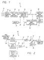
- Fig. 1 is a schematic of an imaging system constructed in accordance with the teachings of the present invention and having a scene-based nonuniformity correction processor.
- Fig. 2 is a schematic of the scene-based nonuniformity correction processor of Fig. 1 incorporating a scene motion detector.
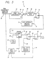
- Fig. 3 is a schematic of the scene motion detector of Fig. 2.
- Fig. 1 is a schematic of an imaging system constructed in accordance with the teachings of the present invention and having a scene-based nonuniformity correction processor.
- the imaging system 10 includes a focal plane array 14 of photon detectors that detects incoming electromagnetic energy signals 16 and converts the signals 16 into a first electronic video data stream 18. Video data from the first video data stream 18 is then processed by a front-end signal processor 20.
- the processor 20 applies "global" offset and/or responsivity values to the video data that are identical for all detectors (not shown) in the focal plane array 14.
- a processed video data stream 22 is output from the processor 20 and provides input to a nonuniformity correction processor 24.
- the nonuniformity correction processor 24 performs correction processing to information contained in the processed video data stream 22. Correction processing performed in the processor 24 accounts for different response characteristics inherent in the focal plane array's 14 individual detectors. Unique offset and responsivity correction terms may he applied to each pixel (not shown) to equalize detector responses.
- a corrected video data stream 26 output from the nonuniformity correction processor 24 provides input to a scene-based nonuniformity correction processor (SBNUC) 30 and a back-end signal processor 28.
- the back-end processor 28 performs final signal processing before the display of video data contained in the corrected video data stream 26.
- an output 29 from the back-end signal processor is input to a video display 31 where video data representative of the electromagnetic energy 16 is displayed.
- the nonuniformity correction processor 24 utilizes pre-determined static correction terms 36 stored in a memory circuit 34.
- the static correction terms aim to eliminate first order nonuniformities and are determined in a calibration procedure known in the art which equalizes detector responses when the focal plane array 14 is exposed to electromagnetic energy 16 having a uniform flux.
- the scene-based nonuniformity correction processor 30 receives the corrected data stream 26 and provides current scene-based nonuniformity correction terms 32 to the nonuniformity correction processor 24.
- the current scene-based nonuniformity correction terms 32 are updated only when the scene (not shown) corresponding to the electromagnetic energy 16 is moving.
- a scene motion detector (not shown) and an external motion control signal (not shown) are used to activate the dynamic action of the scene-based nonuniformity processor 30 when the scene is moving. This prevents the processor 30 from degrading scene features or details when the scene is not moving as happens with conventional scene-based nonuniformity correction circuits. This also increases the applicability of the system 10 to applications involving stationary scenes such as tactical vehicle imaging systems.
- the current scene-based nonuniformity correction terms 32 are updated in near-real-time by the scene-based nonuniformity correction processor 30 in response to a changing scene environment as communicated via the corrected video data stream 26.
- the current scene-based correction terms 32 augment the pre-determined static correction terms 36 stored in the memory circuit 34.
- the correction processor 24 applies both static and "dynamic" scene-based correction terms to the processed video data stream 22 to produce the corrected video data stream 26 that is then input back into the scene-based nonuniformity correction processor 30 for any further correcting, and so on. In this way fixed-pattern noise due to differences in individual detector responses of the focal plane array 14 is minimized.
- static correction terms are not used. Instead, first and higher order correction terms are all determined in real time and applied to the processed video data stream 22 in one of the nonuniformity correction processors 24, 30.
- the focal plane array 14, the front-end signal processor 20, the nonuniformity correction processor 24, the back-end signal processor 28, the video display 31, and the memory 34 are conventional devices and modules.
- the scene-based nonuniformity correction processor 30 has a unique design as disclosed in Fig. 2.
- Fig. 2 is a schematic of the scene-based nonuniformity correction processor of Fig. 1 incorporating a scene motion detector.
- the scene-based nonuniformity correction processor 30 includes a scene-based nonuniformity correction (SBNUC) filter 38 and a scene motion detector 40 that receive the corrected video data stream 26.
- the filter 38 is a conventional scene-based nonuniformity correction filter that provides intermediate scene-based correction terms 42 to an input of an AND gate 44.
- the intermediate scene-based correction terms 42 account for changing scene conditions.
- the AND gate 44 may be replaced by a pass gate without departing from the scope of the present invention.
- the scene motion detector 40 receives information about the scene (not shown) via the video data stream 26 and determines if the scene has sufficient motion to enable the intermediate correction terms 42 to update the previously generated scene-based correction terms 56.
- a scene motion signal 46 that is output from the detector 40 is input to an OR gate 48.
- the OR gate 48 also has an external motion input signal 52 as an input from an external motion signal generator 51.
- the external generator 51 may correspond to an aiming system servo circuit in a missile system.
- the external motion signal 52 and the OR gate 48 are not required for the present invention: a scene-motion detector alone is sufficient.
- the depiction of both a scene motion detector circuit and an external motion signal are intended to demonstrate two possible independent origins for a satisfactory motion-triggering signal. Either one alone could be acceptable depending on the specifics of the application.
- the external input signal 52 may provide movement information from any actuators (not shown) that control movement of the focal plane array (see Fig. 1). If one or both of the input signals 46, 52 to the OR gate 48 signal that sufficient scene motion is present, the OR gate 48 will provide a motion control signal 50 to an input of the AND gate 44 specifying that sufficient scene motion is present to enable intermediate scene-based correction terms 42 to update the previously generated scene-based correction terms 56.
- a high voltage state at the output of the OR gate 48 corresponds to a motion-present motion control signal 50.
- the motion control signal 50 is high, i.e., sufficient scene motion is present, an output 53 of the AND gate 44 will correspond to the intermediate scene-based correction term updates 42 input to the AND gate 44.
- the output 53 represents gated scene-based correction term updates.
- Gated scene-based correction term updates 53 are input to a conventional adder 54 that also has previously generated scene-based correction terms 56 as input.
- the previously generated scene-based correction terms 56 are stored in a conventional memory device 58.
- Output from the adder 54 represents current scene-based correction terms 32 that are combination of the gated scene-based correction term updates 53 and the previously generated scene-based correction terms 56.
- the current scene-based correction terms 32 are input to the memory, device 58 for storage until required for another iteration.
- Fig. 3 is a schematic of a representative scene motion detector circuit 40 depicted in Fig. 2.
- the scene motion detector 40 includes a frame integrator 60 and a conventional subtractor 62 that receive the current video data stream 26 as input.
- the frame integrator 60 computes a running frame average 64 of current and previous video frames from information provided by the current video data stream 26.
- the running frame average 64 contains information pertaining to the average video level for each pixel in the video frame and is also input to the subtractor 62.
- the subtractor 62 computes a difference 66 between video levels of the running frame average 64 and the current video frame as input by the video data stream 26.
- the difference 66 contains information pertaining to the difference between the average video level and the current video level for each pixel in the current video frame.
- the difference 66 is then input into a conventional absolute value computation circuit 68 that provides the absolute value of the difference 66 to a video difference comparator 72 via a video difference signal 70.
- the absolute value computation circuit 68 calculates the magnitude of the difference between the average video level and the current video level for each pixel in the current video frame.
- the video difference comparator 72 has an additional input 74 corresponding to a pre-determined programmable video threshold from a video difference threshold generator 73.
- An appropriate video threshold is determined through experimentation and is used to set the generator 73 or is determined via a specialized algorithm running on the generator 73. The threshold is set so that temporal noise characteristics of the imaging system and surrounding environment do not cause static pixels to be misconstrued.
- the comparator 72 compares the video difference 70 for each pixel to the programmable video threshold 74. If the video difference 70 exceeds the threshold 74 then a counter 76 is enabled via a comparator output 78. If the video difference 70 is less than or equal to the video threshold 74 then the counter 76 is not enabled.
- a counter enabling signal at the output 78 of the comparator signifies scene motion has taken place sufficient to cause the video difference 70 of a particular pixel to exceed the threshold 74. However, this scene motion may not be sufficient to require activating of the scene motion detection circuit 40 of Fig. 2.
- the counter 76 has a conventional pixel clock signal 80 from a pixel clock 81 and a start of video frame signal 82 from a video frame counter 83 as additional inputs.
- the video frame counter 83 processes the data stream 26 to determine when one video frame begins and another one ends.
- the signal 82 When the start of a video frame is encountered, the signal 82 resets an in-motion pixel count stored in the counter 76.
- the pixel clock 81 triggers an increment of the in-motion pixel count stored in the counter 76 for each pixel having a video difference 70 that enables the counter 76.
- An output 84 of the counter 76 corresponding to the in-motion pixel count provides input to a pixel count comparator 86.
- the pixel count comparator 86 has an additional input 88 corresponding to a pre-determined programmable pixel count threshold from a pixel count threshold generator 87.
- An appropriate pixel count threshold is determined through experimentation and is used to set the generator 87, or through the use of a specialized algorithm running on the generator 87.
- the threshold 88 may be different for different applications.
- the in-motion pixel count 84 is compared to the programmable pixel count threshold 88 by comparator 86. If the pixel count 84 exceeds the threshold 88, then the current video frame has sufficient motion to enable the intermediate scene-based correction terms 42 of Fig. to update the previously generated scene-based correction terms 56. In this case, an in-motion signal will be transferred to the input of a status register 92 via a comparator output 90.
- the status register is a D flip-flop of conventional design.
- a high voltage state at the output 90 corresponds to an in-motion signal
- a low voltage state at the output 90 corresponds to a not-in-motion signal
- the status register 92 includes an end of video frame signal 94 from the video frame counter 83 as an additional input.
- the end of video frame signal 94 clocks the value at the output 90 into the status register 92 and provides the scene motion signal 46.
- each current video frame has its own motion status value depending on whether or not the video frame is sufficiently moving to enable scene-based nonuniformity correction updates. This value corresponds to the scene motion signal 46.
- the modules and components used in the motion detection circuit 40 are modules and components of conventional design, however those skilled in the art will appreciate that inventive modules and components may be used in place of the conventional modules without departing from the scope of the present invention.
- functions performed by the components depicted in the schematic diagram of Fig. 1 may be reallocated to different components. For example, rather than feeding back current scene based correction terms to the nonuniformity correction processor 24 on line 32, the SBNUC processor 30 could perform the corrections and feed the data to the video signal processor 28 directly.
Landscapes
- Engineering & Computer Science (AREA)
- Multimedia (AREA)
- Signal Processing (AREA)
- Transforming Light Signals Into Electric Signals (AREA)
- Photometry And Measurement Of Optical Pulse Characteristics (AREA)
- Nuclear Medicine (AREA)
- Image Processing (AREA)
Abstract
Description
Claims (11)
- A nonuniformity correction processor (10, 30) for correcting information (18, 22, 26) received from a scene (16) via an array of energy detectors (14) characterized by:A nonuniformity correction mechanism (24, 32, 34, 36, 38, 42, 53, 54, 56, 58) for generating current nonuniformity correction terms (32) and applying the terms (32) to the information (22, 26) received from the scene (16);A motion detection mechanism (40, 46, 48, 52) for determining when the scene (16) is moving and for providing a motion signal (50) in response thereto; andA triggering mechanism (44) for selectively enabling the nonuniformity correction mechanism (24, 32, 34, 36, 38, 42, 53, 54, 56, 58) in response to the motion signal (46, 50).
- The invention of Claim 1 wherein the nonuniformity correction terms (32) are dynamic second order terms that account for changing scene conditions.
- The invention of Claim 1 wherein the nonuniformity correction mechanism (24, 32, 34, 36, 38, 42, 53, 54, 56, 58) includes filtering mechanism (38) for generating intermediate nonuniformity correction terms (42, 53) in response to the information (18, 22, 26) received from the array energy detectors (14).
- The invention of Claim 3 wherein the nonuniformity correction mechanism (24, 32, 34, 36, 38, 42, 53, 54, 56, 58) further includes updating mechanism (32, 54, 56, 58) for providing and storing the current correction terms (32).
- The invention of Claim 4 wherein the current correction terms (32) are obtained from a combination of the intermediate nonuniformity correction terms (53) and pre-existing correction terms (56) stored in the updating mechanism (32, 54, 56, 58).
- The invention of Claim 1 wherein the motion detection mechanism (40, 46, 48, 52) includes a scene motion detection circuit (40).
- The invention of Claim 6 wherein the output (46) of the motion detection circuit (40) is connected to one input of an OR gate (48) having an external motion input signal (52) as a second input and the output (50) of the OR gate (48) is input to the triggering mechanism (44).
- The invention of Claim 6 wherein the scene motion detection circuit (40) includes mechanism (26, 60, 62, 64, 66, 68, 70, 72, 74, 78, 76, 80, 82, 84, 86, 88) for testing pixels and providing a count of the number of pixels that differ from a predetermined pixel value by a predetermined threshold (74).
- The invention of Claim 8 wherein the pre-determined pixel value is the average pixel value of a given pixel under test in a pre-determined number of image frames and the pre-determined threshold is a difference video threshold (74).
- The invention of Claim 8 wherein said mechanism (26, 60, 62, 64, 66, 68, 70, 72, 74, 78, 76, 80, 82, 84, 86, 88) for testing and counting includes a pixel count comparator (86) for comparing said count of pixels to a pre-determined pixel count threshold (88).
- The invention of Claim 1 wherein the triggering mechanism (44) includes a gating device (44) having the motion signal (50), and the intermediate correction terms (42) as inputs and having an output (53) connected to an updating mechanism (32, 54, 56, 58) included in the nonuniformity correction mechanism (24, 32, 34, 36, 38, 42, 53, 54, 56, 58), said updating mechanism (32, 54, 56, 58) for providing and storing the current correction terms (32).
Applications Claiming Priority (2)
| Application Number | Priority Date | Filing Date | Title |
|---|---|---|---|
| US769558 | 1996-12-19 | ||
| US08/769,558 US5721427A (en) | 1996-12-19 | 1996-12-19 | Scene-based nonuniformity correction processor incorporating motion triggering |
Publications (3)
| Publication Number | Publication Date |
|---|---|
| EP0849941A2 true EP0849941A2 (en) | 1998-06-24 |
| EP0849941A3 EP0849941A3 (en) | 2000-05-17 |
| EP0849941B1 EP0849941B1 (en) | 2004-09-01 |
Family
ID=25085812
Family Applications (1)
| Application Number | Title | Priority Date | Filing Date |
|---|---|---|---|
| EP97307651A Expired - Lifetime EP0849941B1 (en) | 1996-12-19 | 1997-09-29 | Scene-based nonuniformity correction processor with motion consideration |
Country Status (5)
| Country | Link |
|---|---|
| US (1) | US5721427A (en) |
| EP (1) | EP0849941B1 (en) |
| JP (1) | JP3208106B2 (en) |
| DE (1) | DE69730481T2 (en) |
| IL (1) | IL121864A (en) |
Cited By (1)
| Publication number | Priority date | Publication date | Assignee | Title |
|---|---|---|---|---|
| WO2006040662A3 (en) * | 2004-10-14 | 2006-12-28 | Nissan Motor | Image processing device and method |
Families Citing this family (37)
| Publication number | Priority date | Publication date | Assignee | Title |
|---|---|---|---|---|
| US6507018B2 (en) * | 1996-08-30 | 2003-01-14 | Raytheon Company | Ditherless non-uniformity compensation for infrared detector arrays with recursive spatial low pass filtering |
| US6040568A (en) * | 1998-05-06 | 2000-03-21 | Raytheon Company | Multipurpose readout integrated circuit with in cell adaptive non-uniformity correction and enhanced dynamic range |
| US6330371B1 (en) * | 1998-10-19 | 2001-12-11 | Raytheon Company | Adaptive non-uniformity compensation using feedforward shunting and min-mean filter |
| US6243498B1 (en) | 1998-10-19 | 2001-06-05 | Raytheon Company | Adaptive non-uniformity compensation using feedforwarding shunting |
| US6215115B1 (en) * | 1998-11-12 | 2001-04-10 | Raytheon Company | Accurate target detection system for compensating detector background levels and changes in signal environments |
| US6700124B1 (en) * | 1999-01-14 | 2004-03-02 | Matsushita Electric Industrial Co., Ltd. | Infrared imaging device, vehicle having the same installed therein, and infrared image adjustment device |
| JP2002077723A (en) * | 2000-09-01 | 2002-03-15 | Minolta Co Ltd | Moving image processor and moving image processing method and recording medium |
| US6973218B2 (en) * | 2001-04-25 | 2005-12-06 | Lockheed Martin Corporation | Dynamic range compression |
| US6901173B2 (en) * | 2001-04-25 | 2005-05-31 | Lockheed Martin Corporation | Scene-based non-uniformity correction for detector arrays |
| US7016550B2 (en) * | 2002-04-19 | 2006-03-21 | Lockheed Martin Corporation | Scene-based non-uniformity offset correction for staring arrays |
| US8958654B1 (en) * | 2001-04-25 | 2015-02-17 | Lockheed Martin Corporation | Method and apparatus for enhancing three-dimensional imagery data |
| US7103235B2 (en) | 2001-04-25 | 2006-09-05 | Lockheed Martin Corporation | Extended range image processing for electro-optical systems |
| US7064785B2 (en) * | 2002-02-07 | 2006-06-20 | Eastman Kodak Company | Apparatus and method of correcting for dark current in a solid state image sensor |
| GB0205482D0 (en) * | 2002-03-08 | 2002-04-24 | Bae Systems Plc | Improvements in or relating to infra red camera calibration |
| US6969858B2 (en) * | 2002-10-22 | 2005-11-29 | Northrop Grumman Corporation | Optical spatial interconnect net |
| DE10255021B4 (en) * | 2002-11-25 | 2007-02-22 | Carl Zeiss Optronics Gmbh | Method and device for generating image data of a scene taking into account inhomogeneities in the signal sensitivities of sensor elements in scanning imaging devices |
| EP1571990B1 (en) * | 2002-12-10 | 2008-06-04 | Koninklijke Philips Electronics N.V. | Activity monitoring |
| US7463753B2 (en) * | 2004-09-15 | 2008-12-09 | Raytheon Company | FLIR-to-missile boresight correlation and non-uniformity compensation of the missile seeker |
| JP4548128B2 (en) * | 2005-01-26 | 2010-09-22 | ソニー株式会社 | Defect detection apparatus, defect detection method, and imaging apparatus |
| US7683945B2 (en) * | 2006-03-30 | 2010-03-23 | Raytheon Company | Responsivity correction for electro-optical imagers |
| US20110169960A1 (en) * | 2006-11-13 | 2011-07-14 | Redshift Systems Corporation | Video enhancement system |
| US20080212895A1 (en) * | 2007-01-09 | 2008-09-04 | Lockheed Martin Corporation | Image data processing techniques for highly undersampled images |
| US9235876B2 (en) | 2009-03-02 | 2016-01-12 | Flir Systems, Inc. | Row and column noise reduction in thermal images |
| US9208542B2 (en) | 2009-03-02 | 2015-12-08 | Flir Systems, Inc. | Pixel-wise noise reduction in thermal images |
| WO2012170949A2 (en) | 2011-06-10 | 2012-12-13 | Flir Systems, Inc. | Non-uniformity correction techniques for infrared imaging devices |
| US9843742B2 (en) | 2009-03-02 | 2017-12-12 | Flir Systems, Inc. | Thermal image frame capture using de-aligned sensor array |
| US10091439B2 (en) | 2009-06-03 | 2018-10-02 | Flir Systems, Inc. | Imager with array of multiple infrared imaging modules |
| US8428385B2 (en) * | 2009-06-24 | 2013-04-23 | Flir Systems, Inc. | Non-uniformity error correction with a bilateral filter |
| US8625005B2 (en) | 2010-11-05 | 2014-01-07 | Raytheon Company | First-in-first-out (FIFO) buffered median scene non-uniformity correction method |
| US9143703B2 (en) | 2011-06-10 | 2015-09-22 | Flir Systems, Inc. | Infrared camera calibration techniques |
| CN103748867B (en) | 2011-06-10 | 2019-01-18 | 菲力尔系统公司 | Low Power and Small Form Factor Infrared Imaging |
| CN102914369B (en) * | 2011-08-05 | 2015-02-04 | 平阳电力有限责任公司 | Online infrared imaging device of transformer substation |
| WO2014100786A1 (en) * | 2012-12-21 | 2014-06-26 | Flir Systems, Inc. | Selective image correction for infrared imaging devices |
| US9924138B1 (en) * | 2015-01-16 | 2018-03-20 | Rockwell Collins, Inc. | Combined air-turbulence, ice, volcanic-ash aerosols, passive LWIR optical systems for cruising-airplane safety |
| CN104867157B (en) * | 2015-06-01 | 2018-02-02 | 北京万东医疗科技股份有限公司 | A kind of bearing calibration of CT detector pixels response nonuniformity |
| US10931901B2 (en) * | 2016-08-31 | 2021-02-23 | Flir Systems Ab | Method and apparatus for selectively correcting fixed pattern noise based on pixel difference values of infrared images |
| US11113791B2 (en) | 2017-01-03 | 2021-09-07 | Flir Systems, Inc. | Image noise reduction using spectral transforms |
Family Cites Families (4)
| Publication number | Priority date | Publication date | Assignee | Title |
|---|---|---|---|---|
| US4975864A (en) * | 1989-01-26 | 1990-12-04 | Hughes Aircraft Company | Scene based nonuniformity compensation for starting focal plane arrays |
| US5323334A (en) * | 1992-12-04 | 1994-06-21 | Hughes Aircraft Company | Sensor system having nonuniformity suppression with image preservation |
| US5471240A (en) * | 1993-11-15 | 1995-11-28 | Hughes Aircraft Company | Nonuniformity correction of an imaging sensor using region-based correction terms |
| US5604347A (en) * | 1995-07-13 | 1997-02-18 | General Electric Company | Method and means for compensating for row variable offsets in a large area solid state x-ray detector |
-
1996
- 1996-12-19 US US08/769,558 patent/US5721427A/en not_active Expired - Lifetime
-
1997
- 1997-09-29 DE DE69730481T patent/DE69730481T2/en not_active Expired - Lifetime
- 1997-09-29 IL IL12186497A patent/IL121864A/en not_active IP Right Cessation
- 1997-09-29 EP EP97307651A patent/EP0849941B1/en not_active Expired - Lifetime
- 1997-12-19 JP JP35155697A patent/JP3208106B2/en not_active Expired - Lifetime
Cited By (2)
| Publication number | Priority date | Publication date | Assignee | Title |
|---|---|---|---|---|
| WO2006040662A3 (en) * | 2004-10-14 | 2006-12-28 | Nissan Motor | Image processing device and method |
| US7865029B2 (en) | 2004-10-14 | 2011-01-04 | Nissan Motor Co., Ltd. | Image processing device and method |
Also Published As
| Publication number | Publication date |
|---|---|
| DE69730481D1 (en) | 2004-10-07 |
| US5721427A (en) | 1998-02-24 |
| IL121864A0 (en) | 1998-02-22 |
| IL121864A (en) | 2000-07-26 |
| EP0849941B1 (en) | 2004-09-01 |
| JPH10271393A (en) | 1998-10-09 |
| EP0849941A3 (en) | 2000-05-17 |
| JP3208106B2 (en) | 2001-09-10 |
| DE69730481T2 (en) | 2005-09-08 |
Similar Documents
| Publication | Publication Date | Title |
|---|---|---|
| US5721427A (en) | Scene-based nonuniformity correction processor incorporating motion triggering | |
| US7103235B2 (en) | Extended range image processing for electro-optical systems | |
| KR101955498B1 (en) | Infrared image correction apparatus using neural network structure and method thereof | |
| EP2171642B1 (en) | System and method of moving target based calibration of non-uniformity compensation for optical imagers | |
| US5925875A (en) | Apparatus and method for compensating for fixed pattern noise in planar arrays | |
| US4771267A (en) | Analog offset compensation technique | |
| US7907192B2 (en) | Electronic imaging system with adjusted dark floor correction | |
| JP2848825B2 (en) | Television camera | |
| US10417745B2 (en) | Continuous motion scene based non-uniformity correction | |
| US20090153725A1 (en) | Image capturing apparatus, control method therefor, and program | |
| EP1615425A1 (en) | Image-pickup device and signal processing method | |
| US5276319A (en) | Method and device for improved IR detection with compensations for individual detector response | |
| US20080291505A1 (en) | Method, apparatus for correcting image signal from image sensor, and imaging system with apparatus | |
| Narendra et al. | Shutterless fixed pattern noise correction for infrared imaging arrays | |
| US20050157942A1 (en) | System and method for estimating noise using measurement based parametric fitting non-uniformity correction | |
| US20080024669A1 (en) | Imaging system | |
| US4388646A (en) | Low-distortion detection of pulses superimposed on an unknown and variable background signal | |
| US12141949B2 (en) | Vehicle-mounted camera apparatus and image distortion correction method | |
| US6243498B1 (en) | Adaptive non-uniformity compensation using feedforwarding shunting | |
| US20040047012A1 (en) | Method and device for imaging using several exposure times | |
| US20220333996A1 (en) | Computational Radiation Tolerance for High Quality Infrared Focal Plane Arrays | |
| JPH11112884A (en) | Method for correcting dark current of video camera device and video camera device using the method | |
| US7084911B1 (en) | Black level calibration method for imager with hysteresis comparison and adaptive step size | |
| US9832401B1 (en) | Minimization of fixed pattern noise in images of moving scenes | |
| US5257061A (en) | Range finder for passive-type autofocusing device |
Legal Events
| Date | Code | Title | Description |
|---|---|---|---|
| PUAI | Public reference made under article 153(3) epc to a published international application that has entered the european phase |
Free format text: ORIGINAL CODE: 0009012 |
|
| AK | Designated contracting states |
Kind code of ref document: A2 Designated state(s): AT BE CH DE DK ES FI FR GB GR IE IT LI LU MC NL PT SE |
|
| RAP1 | Party data changed (applicant data changed or rights of an application transferred) |
Owner name: RAYTHEON COMPANY |
|
| PUAL | Search report despatched |
Free format text: ORIGINAL CODE: 0009013 |
|
| AK | Designated contracting states |
Kind code of ref document: A3 Designated state(s): AT BE CH DE DK ES FI FR GB GR IE IT LI LU MC NL PT SE |
|
| 17P | Request for examination filed |
Effective date: 20001023 |
|
| AKX | Designation fees paid |
Free format text: DE ES FR GB IT NL |
|
| 17Q | First examination report despatched |
Effective date: 20030520 |
|
| GRAP | Despatch of communication of intention to grant a patent |
Free format text: ORIGINAL CODE: EPIDOSNIGR1 |
|
| GRAS | Grant fee paid |
Free format text: ORIGINAL CODE: EPIDOSNIGR3 |
|
| GRAA | (expected) grant |
Free format text: ORIGINAL CODE: 0009210 |
|
| AK | Designated contracting states |
Kind code of ref document: B1 Designated state(s): DE ES FR GB IT NL |
|
| PG25 | Lapsed in a contracting state [announced via postgrant information from national office to epo] |
Ref country code: NL Free format text: LAPSE BECAUSE OF FAILURE TO SUBMIT A TRANSLATION OF THE DESCRIPTION OR TO PAY THE FEE WITHIN THE PRESCRIBED TIME-LIMIT Effective date: 20040901 Ref country code: IT Free format text: LAPSE BECAUSE OF FAILURE TO SUBMIT A TRANSLATION OF THE DESCRIPTION OR TO PAY THE FEE WITHIN THE PRESCRIBED TIME-LIMIT;WARNING: LAPSES OF ITALIAN PATENTS WITH EFFECTIVE DATE BEFORE 2007 MAY HAVE OCCURRED AT ANY TIME BEFORE 2007. THE CORRECT EFFECTIVE DATE MAY BE DIFFERENT FROM THE ONE RECORDED. Effective date: 20040901 |
|
| REG | Reference to a national code |
Ref country code: GB Ref legal event code: FG4D |
|
| REF | Corresponds to: |
Ref document number: 69730481 Country of ref document: DE Date of ref document: 20041007 Kind code of ref document: P |
|
| PG25 | Lapsed in a contracting state [announced via postgrant information from national office to epo] |
Ref country code: ES Free format text: LAPSE BECAUSE OF FAILURE TO SUBMIT A TRANSLATION OF THE DESCRIPTION OR TO PAY THE FEE WITHIN THE PRESCRIBED TIME-LIMIT Effective date: 20041212 |
|
| NLV1 | Nl: lapsed or annulled due to failure to fulfill the requirements of art. 29p and 29m of the patents act | ||
| ET | Fr: translation filed | ||
| PLBE | No opposition filed within time limit |
Free format text: ORIGINAL CODE: 0009261 |
|
| STAA | Information on the status of an ep patent application or granted ep patent |
Free format text: STATUS: NO OPPOSITION FILED WITHIN TIME LIMIT |
|
| 26N | No opposition filed |
Effective date: 20050602 |
|
| REG | Reference to a national code |
Ref country code: FR Ref legal event code: PLFP Year of fee payment: 20 |
|
| PGFP | Annual fee paid to national office [announced via postgrant information from national office to epo] |
Ref country code: GB Payment date: 20160928 Year of fee payment: 20 Ref country code: DE Payment date: 20160920 Year of fee payment: 20 |
|
| PGFP | Annual fee paid to national office [announced via postgrant information from national office to epo] |
Ref country code: FR Payment date: 20160816 Year of fee payment: 20 |
|
| REG | Reference to a national code |
Ref country code: DE Ref legal event code: R071 Ref document number: 69730481 Country of ref document: DE |
|
| REG | Reference to a national code |
Ref country code: GB Ref legal event code: PE20 Expiry date: 20170928 |
|
| PG25 | Lapsed in a contracting state [announced via postgrant information from national office to epo] |
Ref country code: GB Free format text: LAPSE BECAUSE OF EXPIRATION OF PROTECTION Effective date: 20170928 |