EP0849904A2 - Synchronous digital transmission system, control device, network element and central clock generator - Google Patents
Synchronous digital transmission system, control device, network element and central clock generator Download PDFInfo
- Publication number
- EP0849904A2 EP0849904A2 EP97440134A EP97440134A EP0849904A2 EP 0849904 A2 EP0849904 A2 EP 0849904A2 EP 97440134 A EP97440134 A EP 97440134A EP 97440134 A EP97440134 A EP 97440134A EP 0849904 A2 EP0849904 A2 EP 0849904A2
- Authority
- EP
- European Patent Office
- Prior art keywords
- clock
- network elements
- network
- control device
- clock generator
- Prior art date
- Legal status (The legal status is an assumption and is not a legal conclusion. Google has not performed a legal analysis and makes no representation as to the accuracy of the status listed.)
- Granted
Links
- 230000001360 synchronised effect Effects 0.000 title claims description 21
- 230000005540 biological transmission Effects 0.000 title claims description 18
- 238000009795 derivation Methods 0.000 claims description 3
- 230000015572 biosynthetic process Effects 0.000 description 3
- RGNPBRKPHBKNKX-UHFFFAOYSA-N hexaflumuron Chemical compound C1=C(Cl)C(OC(F)(F)C(F)F)=C(Cl)C=C1NC(=O)NC(=O)C1=C(F)C=CC=C1F RGNPBRKPHBKNKX-UHFFFAOYSA-N 0.000 description 2
- 230000001419 dependent effect Effects 0.000 description 1
- 230000007257 malfunction Effects 0.000 description 1
- 238000012544 monitoring process Methods 0.000 description 1
- 230000003287 optical effect Effects 0.000 description 1
- 238000002202 sandwich sublimation Methods 0.000 description 1
Images


Classifications
-
- H—ELECTRICITY
- H04—ELECTRIC COMMUNICATION TECHNIQUE
- H04J—MULTIPLEX COMMUNICATION
- H04J3/00—Time-division multiplex systems
- H04J3/02—Details
- H04J3/06—Synchronising arrangements
- H04J3/0635—Clock or time synchronisation in a network
- H04J3/0638—Clock or time synchronisation among nodes; Internode synchronisation
- H04J3/0647—Synchronisation among TDM nodes
-
- H—ELECTRICITY
- H04—ELECTRIC COMMUNICATION TECHNIQUE
- H04J—MULTIPLEX COMMUNICATION
- H04J2203/00—Aspects of optical multiplex systems other than those covered by H04J14/05 and H04J14/07
- H04J2203/0001—Provisions for broadband connections in integrated services digital network using frames of the Optical Transport Network [OTN] or using synchronous transfer mode [STM], e.g. SONET, SDH
- H04J2203/0028—Local loop
- H04J2203/0039—Topology
- H04J2203/0042—Ring
-
- H—ELECTRICITY
- H04—ELECTRIC COMMUNICATION TECHNIQUE
- H04J—MULTIPLEX COMMUNICATION
- H04J2203/00—Aspects of optical multiplex systems other than those covered by H04J14/05 and H04J14/07
- H04J2203/0001—Provisions for broadband connections in integrated services digital network using frames of the Optical Transport Network [OTN] or using synchronous transfer mode [STM], e.g. SONET, SDH
- H04J2203/0057—Operations, administration and maintenance [OAM]
- H04J2203/006—Fault tolerance and recovery
-
- H—ELECTRICITY
- H04—ELECTRIC COMMUNICATION TECHNIQUE
- H04J—MULTIPLEX COMMUNICATION
- H04J3/00—Time-division multiplex systems
- H04J3/02—Details
- H04J3/06—Synchronising arrangements
- H04J3/0635—Clock or time synchronisation in a network
- H04J3/0685—Clock or time synchronisation in a node; Intranode synchronisation
- H04J3/0688—Change of the master or reference, e.g. take-over or failure of the master
Definitions
- the invention relates to a synchronous digital Message transmission system, a control device for one Network node of a synchronous digital message transmission system, a network element and a central clock generator for a network node of a synchronous digital communication system.
- SDH synchronous digital hierarchy
- SONET Synchronous Optical Network
- a Network element receives message signals at two inputs, of which a clock is derived that can be used for synchronization.
- the accuracy of the clocks of these message signals is one of them included quality indicator, hereinafter referred to as SSM (Synchronization Status Message, see e.g. ITU-T recommendations G.707, G.708 or G.709).
- a selector in the network element chooses based on the SSM one of the clocks as a reference clock and guides it a central clock generator of the network node.
- This central Clock generator distributes the reference clock to all network elements of the Network node.
- the central clock generator is a can be an independent unit or that the clock generator Network element, preferably that of a cross-connect, as the central one Clock generator can be used.
- an additional SSM is defined: "Do not use for synchronization", hereinafter referred to as DNU are sent from a network element to all outputs that are connected to the Network element, which is selected as a reference clock source, are connected.
- the network elements of the network node the origin of the selected Do not know the reference clock, nor its accuracy.
- the central clock generator can not provide this information because a Selection of the clock in the selection device of a network element is made.
- the network elements can be used in the SSM as accuracy your reference clock only the accuracy of the central clock generator in free, unsynchronized operation indicate what is usually in ITU-T G.812 corresponds to the specified accuracy.
- the SSM DNU are not sent on the outputs that are used for the Synchronization used reference clock source are connected because of this Reference clock source is not known to the network elements. This can lead to Lead formation of synchronization loops.
- the object of the invention is a synchronous digital Message transmission system to indicate the transmission a quality indicator (SSM) according to the accuracy of the in one Network clock used reference clock is enabled.
- Another The object of the invention is a control device for a Specify network nodes of such a message transmission system.
- Further objects of the invention are a network element and a central clock generator for such a communication system specify.
- An advantage of the invention is that the formation of Synchronization loops in a synchronous according to the invention digital messaging system is avoided.
- Network elements in a synchronous digital Communication systems work synchronously with each other by their own clock on one received by one Match message signal derived clock. Because network elements If there are multiple inputs receiving message signals, a selection is made between the multiple received message signals which clock the internal clock is tuned, i.e. what measure as Reference clock is used. One in each serves for selection Message signal transmitted quality indicator, as for example in ITU-T recommendation G.707. This quality indicator gives that Accuracy of the clock of the respective message signal and is in hereinafter referred to as SSM (Synchronization Status Message).
- the selection of a reference clock takes place in one central clock generator instead, whose job is to control all network elements to supply a network node with a central reference clock.
- a another important point of the invention is that the central clock generator to a control device a message about his Sends synchronization state. The message contains the accuracy of the selected measure as the reference measure and the origin of this measure.
- the Control device in turn sends to all network elements of the Network node instructions, which quality indicator this on which Have to send output.
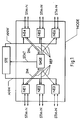
- a network node NODE and a control device STE contains NODE six network elements NE1, ..., NE6, which are transmitted via a transmission medium other, not shown network elements of the synchronous digital Communication system are connected and message signals Send and receive STM-N.
- NODE six network elements NE1, ..., NE6, which are transmitted via a transmission medium other, not shown network elements of the synchronous digital Communication system are connected and message signals Send and receive STM-N.
- this is for everyone Network element indicated by two double arrows. However, this means not that the six network elements NE1, ..., NE6 with two others Network elements are connected, but indicates that each of the six Network elements NE1, ..., NE6 from one or more of the others, not network elements shown receives and sends message signals.
- the six network elements NE1, ..., NE6 have a central one Clock generator SASE connected and get a reference clock from it REF, to which each network element NE1, ..., NE6 of the network node NODE tunes his own clock.
- the network elements NE1, ..., NE6 work synchronously with each other.
- the central clock generator SASE again with clock signal outputs from two of the network elements NE1, NE4 connects and receives clock signals 2M from these.
- Such one Clock signal 2M contains a clock that the sending network element NE1, NE4 derived from a received message signal STM-N and additionally a quality indicator that indicates the accuracy of the clock is contained in the message signal STM-N.
- the clock signal is a Signal with a transmission rate of 2 Mbit / s and at the clock by one Clock with a pulse repetition frequency of 2 MHz, that of a Message signal STM-N of the synchronous digital hierarchy (SDH) is derived.
- the quality indicator (SSM) transferred according to ITU-T recommendation G.707 within the framework of the received message signal STM-N is included.
- the central clock generator SASE selects one of the clock signals 2M based on the quality indicators, derives from the selected clock signal 2M a clock and tunes its internal clock with this clock.
- This internal clock provides the reference clock source of the network node NODE and from it the reference clock for the network elements NE1, ..., NE6 tapped.
- a malfunction e.g. in the event of failure of certain Message signals from which the clock signals are derived are running Central clock generator clock in free, unsynchronized Operation continues and continues to provide a reference clock REF for the Network node NODE.
- the accuracy of the reference clock outdoors, unsynchronized operation then corresponds to the accuracy of the clock, what in the exemplary embodiment the accuracy specified in ITU-T G.812 is.
- the control device STE in the first embodiment is included connected to the central clock generator SASE and receives from it a message STAT about its synchronization status. Content of this Notification is the accuracy of the selected measure according to the associated SSM and the origin of the measure, i.e. of which Network element, the selected clock signal is received and on which the clock signal inputs the clock signal is present.
- the connection between central Clock generator SASE and control device STE have an X.25 interface utilized.
- the message STAT is always from the central clock generator SASE sent if this, for example due to a failure of the selected clock signal, another clock signal for matching its Clock selects.
- the transmission of this communication to the The control device is not time-critical since there is a change the accuracy of the reference clock REF only after a proportional long period of a few hours or days on the synchronous digital messaging system affects. This is due to the prescribed high accuracies of the received clocks and the high accuracy of the clock generator in free, unsynchronized operation, for example for SDH in ITU-T recommendations G.811, G.812 and G.813 are defined.
- An impact on the synchronous digital For example, the messaging system could increase the Slip rates.
- the control device STE has a connection to the individual Network elements NE1, ..., NE6, via which they send instructions ANW to the Network elements NE1, ..., NE6 transmits.
- this is by a thicker line, which does not mean that it is a parallel connection over which all network elements are the same Receive instruction, but each network element receives one or more own instructions.
- This information can over the existing Q interfaces of the network management, which are in the ITU-T Recommendations Q.811 and Q.812 are set to be transferred.
- the Instructions ANW relate to the SSM, which are the network elements NE1, ..., NE6 at their individual outputs in those to be sent at these outputs Message signals to transmit STM-N.
- FIG 2 shows a second embodiment of a Control device STE.
- Die Control device STE exists in this second exemplary embodiment consisting of two separate units: a first control unit SSU-M, which is connected to the central clock generator SASE and one second control unit SDH-M, which with the network elements NE1, ..., NE6 communicates.
- the two control units are one below the other connected by a transmission medium Q. It is advantageous is a Q interface.
- SSU-M is a control unit for control and monitoring a number of central clock generators of different network nodes.
- the second control device is used to control and monitor Network elements of the synchronous digital transmission system.
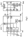
- the network element NE1 and the central clock generator SASE from the The first two exemplary embodiments are shown in detail in FIG. 3.
- the network element has four connection units IO1, ..., IO4, on which message signals STM-N from others, not shown Network elements are received and sent to them.
- Two of the Connection units IO1, IO2 is a clock derivation circuit TA assigned, from which the received message signals STM-N Clock is derived.
- the two connection units IO1, IO2 read the SSM of the received message signal STM-N. With the derived clock, a clock signal 2M is generated, which contains the SSM.
- These clock signals 2M are at two clock signal outputs O1, O2 tapped.
- the network element NE1 also has a reference clock input which is a reference clock REF from the central clock generator SASE Will be received.
- the reference clock REF is a clock SEC of the Network element NE1 fed to this with the reference clock REF vote.
- the network element NE1 Instructions ANW received from a control device. The Instructions apply to the SSM, which are issued by the individual Connection units in the message signals STM-N are sent should.
- the central clock generator has six in the exemplary embodiment Clock signal inputs I1, ..., I6, at which clock signals 2M from network elements be received.
- they are two Clock signal inputs I1, I2 with the two clock signal outputs O1, O2 des Network element NE1 connected.
- the remaining clock signal inputs can connected to clock signal outputs of other network elements of the node be.
- the clock signal inputs I1, ..., I6 are with a selection device SEL connected. This evaluates the SSM contained in the clock signals and uses the SSM to select the clock signal with the most accurate clock. If several clock signals have the same clock quality, either one can predetermined order of priority to choose from, so that the clock signal of a certain clock signal input selected with the same quality preferred or a random selection can be made.
- a clock is derived from the selected clock signal and one Clock generator GEN of the central clock generator SASE supplied to this vote.
- the clock generator GEN supplies the reference clock REF for all Network elements of the node and is with a reference clock output CO connected at which the reference clock can be tapped.
- This Reference clock output CO is connected to the reference clock input Cl des Network element NE1 connected.
- a synchronous digital communication system from a third party, in Figure 3 illustrated embodiment contains three one below the other connected network nodes NODE1, NODE2, NODE3 and one Control device STE.
- Each of the three network nodes consists of three Network elements NE11, ..., NE13, ..., NE31, ..., NE33 and a central one Clock generator SASE1, ..., SASE3.
- network nodes are not limited to three.
- the network elements of a Network nodes receive reference clock lines from the central one Clock generator of the network node a reference clock REF.
- the central one Clock generator receives clock signals 2M from the network elements. Of the Connections through which the central clock generators generate the clock signals received, only those are shown that the respective central Clock generator has been selected to tune its clock.
- the central clock generators SASE1, ..., SASE3 are connected to the control device STE and transmit STAT to these messages via their synchronization state. On the basis of these messages, the control device sends instructions ANW to the individual network elements NE11, ..., NE13, ..., NE31, ..., NE33, which SSM they should send at their individual outputs.
- the central clock generator SASE3 of the third network node NODE3 has selected a clock signal 2M from the network element NE32 in order to synchronize its clock generator.
- the clock contained therein comes from a source, not shown, to which the network element NE32 is connected via communication links STM-N and has the accuracy specified in ITU-T recommendation G.811.
- the central clock generator SASE3 informs the control device STE that it has selected the clock signal from network element NE32 for the reference clock and that this clock has the accuracy G.811.
- the central controller then gives the network elements instructions ANW which SSM they have to send at their outputs.
- Table 1 lists which SSMs the network elements send at their outputs. SSM which is sent by the individual network elements at the various outputs.
- the reference clock of the third network node NODE3 has the accuracy G.811.
- Send the network elements NE31, ..., NE33 of the third network node therefore the code G.811 in the SSM.
- the network element NE23 of the second Network node also receives a message signal from network element NE31 said clock quality, derives a clock signal from it and sends this to the central clock generator SASE2 of the second network node. This selects the clock signal as the reference clock for the second network node NODE2 and distributes the clock to the connected network elements NE21, ..., NE23.
- the message to the control unit contains the message that the message signal from.
- the control device shares this Network element NE23 now that the network element NE31 the SSM DNU ("do not use for synchronization") should send to the network element NE12, however, the SSM G.811.
- the network elements NE22 and NE21 are also instructs to send the SSM G.811.
- the network element NE11 of the first network node NODE1 receives from Network element NE21 and one network signal from network element NE22, that contains the SSM G.811. It initiates from each of these message signals Clock signal for the central clock generator SASE1 of the first network node NODE1 from.
- the central clock generator SASE1 selects one of these Clock signals and divides the choice and accuracy of the chosen one Clock signals from the control device STE with.
- the control device STE instructs the network elements NE11 and NE12 towards the second Network node to send the SSM DNU.
- the network element NE13 the SSM DNU to the network element NE31 of the third network node NODE3 send, so that no clock loop can arise by the clock generator SASE3 of the third network node NODE3 for tuning its clock selects a clock signal which the clock of the network element NE13 received message signal contains.
- the control device STE determines the instructions ANW on the Basis of the communications STAT. You can do this in a memory Control device, for example given tables, the for each possible combination of messages from the connected central clock generators the instructions for the individual network elements contains. Another possibility is that the central control about information about the configuration of the connected Network node, i.e. what connections between the network nodes exist and at which inputs of the central clock generators Clock signal received from these connections Message signals is derived is present. With the help of this information The central controller can determine which SSM from each Network elements must be sent.
Abstract
Description
Die Erfindung betrifft ein synchrones digitales Nachrichtenübertragungssystem, eine Steuerungseinrichtung für einen Netzknoten eines synchronen digitalen Nachrichtenübertragungssystems, ein Netzelement und einen zentralen Taktgenerator für einen Netzknoten eines synchronen digitalen Nachrichtenübertragungssystems.The invention relates to a synchronous digital Message transmission system, a control device for one Network node of a synchronous digital message transmission system, a network element and a central clock generator for a network node of a synchronous digital communication system.
Ein synchrones digitales Nachrichtenübertragungssystem ist beispielsweise ein SDH-System oder SONET-System; (SHD=synchrone digitale Hierarchie, SONET=Synchronous Optical Network). Bei der Nachrichtenübertragung in einem solchen Nachrichtenübertragungssystem kommt es wesentlich darauf an, daß alle Netzelemente (z.B. Add/Drop-Multiplexer, Crossconnects oder Leitungsmultiplexer) synchron miteinander arbeiten. Weiterhin schreibt die ITU-Empfehlung G.803 vor, daß ein Netzknoten, der mehrere Netzelemente enthält, von einem einzigen zentralen Taktgenerator des Netzknotens mit einem Referenztakt versorgt werden muß.A synchronous digital message transmission system is for example an SDH system or SONET system; (SHD = synchronous digital hierarchy, SONET = Synchronous Optical Network). When sending messages in such a messaging system is essential assumes that all network elements (e.g. add / drop multiplexer, crossconnects or Line multiplexer) work synchronously with each other. Furthermore writes the ITU recommendation G.803 proposed that a network node that had several Contains network elements from a single central clock generator Network node must be supplied with a reference clock.
Ein Konferenzartikel von Dr. M. Wolf, 8th European Frequency and Time Forum 9.-11.3. 1994, TU München, S. 166 bis 174, beschreibt wie in einem Netzknoten die Synchronisierung der Netzelemente eines solchen synchronen digitalen Nachrichtenübertragungssystems erfolgen kann: Ein Netzelement empfängt an zwei Eingängen Nachrichtensignale, von denen ein Takt abgeleitet wird, der zur Synchronisation verwendet werden kann. Die Genauigkeit der Takte dieser Nachrichtensignale gibt ein darin enthaltener Qualitätsindikator an, im folgenden als SSM bezeichnet (Synchronization Status Message, siehe z.B. ITU-T Empfehlungen G.707, G.708 oder G.709). Eine Auswahleinrichtung in dem Netzelement wählt anhand der SSM einen der Takte als Referenztakt aus und leitet diesen an einen zentralen Taktgenerator des Netzknotens weiter. Dieser zentrale Taktgenerator verteilt den Referenztakt an alle Netzelemente des Netzknotens. Es ist auch beschrieben, daß der zentrale Taktgenerator eine eigenständige Einheit sein kann oder daß der Taktgenerator eines Netzelementes, vorzugsweise der eines Crossconnects, als zentraler Taktgenerator verwendet werden kann. Um die Bildung von Synchronisationsschleifen zu verhindern, d.h. daß zwei Netzelemente sich gegenseitig als Referenztaktquelle nutzen, ist eine zusätzliche SSM definiert: ,,Do not use for synchronization", im folgenden DNU genannt. Diese soll von einem Netzelement an allen Ausgängen gesendet werden, die mit dem Netzelement, welches als Referenztaktquelle ausgewählt ist, verbunden sind.A conference article by Dr. M. Wolf, 8th European Frequency and Time Forum March 9-11 1994, TU Munich, pp. 166 to 174, describes as in a network node the synchronization of the network elements of such synchronous digital messaging system can be: A Network element receives message signals at two inputs, of which a clock is derived that can be used for synchronization. The accuracy of the clocks of these message signals is one of them included quality indicator, hereinafter referred to as SSM (Synchronization Status Message, see e.g. ITU-T recommendations G.707, G.708 or G.709). A selector in the network element chooses based on the SSM one of the clocks as a reference clock and guides it a central clock generator of the network node. This central Clock generator distributes the reference clock to all network elements of the Network node. It is also described that the central clock generator is a can be an independent unit or that the clock generator Network element, preferably that of a cross-connect, as the central one Clock generator can be used. To the formation of Prevent synchronization loops, i.e. that two network elements mutually use as reference clock source, an additional SSM is defined: "Do not use for synchronization", hereinafter referred to as DNU are sent from a network element to all outputs that are connected to the Network element, which is selected as a reference clock source, are connected.
Ein Problem, das mit der dargestellten Lösung verbunden ist, liegt darin, daß die Netzelemente des Netzknotens die Herkunft des ausgewählten Referenztaktes nicht kennen, ebensowenig dessen Genauigkeit. Auch der zentrale Taktgenerator kann diese Information nicht liefern, da eine Auswahl des Taktes in der Auswahleinrichtung eines Netzelementes vorgenommen wird. Die Netzelemente können in der SSM als Genauigkeit ihres Referenztaktes also nur die Genauigkeit des zentralen Taktgenerators im freien, unsynchronisierten Betrieb angeben, was in der Regel der in ITU-T G.812 festgelegten Genauigkeit entspricht. Zudem kann die SSM DNU nicht an den Ausgängen gesendet werden, die mit der zur Synchronisierung verwendeten Referenztaktquelle verbunden sind, da diese Referenztaktquelle den Netzelementen nicht bekannt ist. Dies kann zur Bildung von Synchronisationsschleifen führen.One problem associated with the solution presented is that the network elements of the network node the origin of the selected Do not know the reference clock, nor its accuracy. Also the central clock generator can not provide this information because a Selection of the clock in the selection device of a network element is made. The network elements can be used in the SSM as accuracy your reference clock only the accuracy of the central clock generator in free, unsynchronized operation indicate what is usually in ITU-T G.812 corresponds to the specified accuracy. In addition, the SSM DNU are not sent on the outputs that are used for the Synchronization used reference clock source are connected because of this Reference clock source is not known to the network elements. This can lead to Lead formation of synchronization loops.
Aufgabe der Erfindung ist es, ein synchrones digitales Nachrichtenübertragungssystem anzugeben, bei dem die Übertragung eines Qualitätsindikators (SSM) entsprechend der Genauigkeit des in einem Netzknoten verwendeten Referenztaktes ermöglicht wird. Eine andere Aufgabe der Erfindung ist es, eine Steuerungseinrichtung für einen Netzknoten eines solchen Nachrichtenübertragungssystem anzugeben. Weitere Aufgaben der Erfindung sind es, ein Netzelement und einen zentralen Taktgenerator für einen solches Nachrichtenübertragungssystem anzugeben.The object of the invention is a synchronous digital Message transmission system to indicate the transmission a quality indicator (SSM) according to the accuracy of the in one Network clock used reference clock is enabled. Another The object of the invention is a control device for a Specify network nodes of such a message transmission system. Further objects of the invention are a network element and a central clock generator for such a communication system specify.
Die Aufgabe wird hinsichtlich des Nachrichtenübertragungssystems gelöst
durch die Merkmale des Patentanspruches 1, hinsichtlich der
Steuerungseinrichtung durch die Merkmale des Patentanspruches 2,
hinsichtlich des Netzelementes durch die Merkmale des Patentanspruches 6
und hinsichtlich des zentralen Taktgenerators durch die Merkmale des
Patentanspruches 8. Vorteilhafte Ausgestaltungen sind den abhängigen
Ansprüchen zu entnehmen.The task is solved with regard to the message transmission system
by the features of
Ein Vorteil der Erfindung besteht darin, daß die Bildung von Synchronisationsschleifen in einem erfindungsgemäßen synchronen digitalen Nachrichtenübertragungssystem vermieden wird.An advantage of the invention is that the formation of Synchronization loops in a synchronous according to the invention digital messaging system is avoided.
Anhand der Figuren 1 bis 4 werden im folgenden Ausführungsbeispiele der Erfindung erläutert. Es zeigen:
Figur 1- eine Steuerungseinrichtung und einen Netzknoten aus mehreren Netzelementen und einem zentralen Taktgenerator,
- Figur 2
- den Netzknoten aus
Figur 1 und eine zweiteilige Steuerungseinrichtung, Figur 3- ein Netzelement, welches mit einem zentralen Taktgenerator verbunden ist, und
- Figur 4
- drei Netzknoten und eine zentrale Steuerungseinrichtung.
- Figure 1
- a control device and a network node comprising a plurality of network elements and a central clock generator,
- Figure 2
- the network node from Figure 1 and a two-part control device,
- Figure 3
- a network element which is connected to a central clock generator, and
- Figure 4
- three network nodes and a central control device.
Netzelemente in einem synchronen digitalen Nachrichtenübertragungssystem arbeiten synchron miteinander, indem sie ihre eigenen Taktgeber auf einen von einem empfangenen Nachrichtensignal abgeleiteten Takt abstimmen. Da Netzelemente an mehreren Eingängen Nachrichtensignale empfangen, findet eine Auswahl zwischen den mehreren empfangenen Nachrichtensignalen statt, auf welchen Takt der interne Taktgeber abgestimmt wird, d.h. welcher Takt als Referenztakt verwendet wird. Zur Auswahl dient ein in jedem Nachrichtensignal übertragener Qualitätsindikator, wie er beispielsweise in der ITU-T Empfehlung G.707 festgelegt ist. Dieser Qualitätindikator gibt die Genauigkeit des Taktes des jeweiligen Nachrichtensignales an und wird im folgenden als SSM (Synchronization Status Message) bezeichnet.Network elements in a synchronous digital Communication systems work synchronously with each other by their own clock on one received by one Match message signal derived clock. Because network elements If there are multiple inputs receiving message signals, a selection is made between the multiple received message signals which clock the internal clock is tuned, i.e. what measure as Reference clock is used. One in each serves for selection Message signal transmitted quality indicator, as for example in ITU-T recommendation G.707. This quality indicator gives that Accuracy of the clock of the respective message signal and is in hereinafter referred to as SSM (Synchronization Status Message).
Erfindungsgemäß findet die Auswahl eines Referenztaktes in einem zentralen Taktgenerator statt, dessen Aufgabe es ist, alle Netzelemente eines Netzknotens mit einem zentralen Referenztakt zu versorgen. Ein anderer wichtiger Punkt der Erfindung ist, daß der zentrale Taktgenerator an eine Steuerungseinrichtung eine Mitteilung über seinen Synchronisationszustand sendet. Die Mitteilung enthält die Genauigkeit des als Referenztakt ausgewählten Taktes und die Herkunft dieses Taktes. Die Steuerungseinrichtung sendet wiederum an alle Netzelemente des Netzknotens Anweisungen, welchen Qualitätsindikator diese an welchem Ausgang zu übermitteln haben.According to the invention, the selection of a reference clock takes place in one central clock generator instead, whose job is to control all network elements to supply a network node with a central reference clock. A another important point of the invention is that the central clock generator to a control device a message about his Sends synchronization state. The message contains the accuracy of the selected measure as the reference measure and the origin of this measure. The Control device in turn sends to all network elements of the Network node instructions, which quality indicator this on which Have to send output.
In einem in Figur 1 gezeigten ersten Ausführungsbeispiel enthält ein synchrones digitales Nachrichtenübertragungssystem einen Netzknoten NODE und eine Steuerungseinrichtung STE. Der Netzknoten NODE enthält sechs Netzelemente NE1, ..., NE6, die über ein Übertragungsmedium mit anderen, nicht gezeigten Netzelementen des synchronen digitalen Nachrichtenübertragungssystems verbunden sind und Nachrichtensignale STM-N senden und empfangen. In der Figur 1 ist dies für jedes Netzelement durch zwei Doppelpfeile angedeutet. Dies bedeutet allerdings nicht, daß die sechs Netzelemente NE1, ..., NE6 mit jeweils zwei anderen Netzelementen verbunden sind, sondern deutet an, daß jedes der sechs Netzelemente NE1, ..., NE6 von einem oder mehreren der anderen, nicht gezeigten Netzelemente Nachrichtensignale empfängt und an diese sendet. In a first exemplary embodiment shown in FIG synchronous digital communication system a network node NODE and a control device STE. The network node contains NODE six network elements NE1, ..., NE6, which are transmitted via a transmission medium other, not shown network elements of the synchronous digital Communication system are connected and message signals Send and receive STM-N. In Figure 1 this is for everyone Network element indicated by two double arrows. However, this means not that the six network elements NE1, ..., NE6 with two others Network elements are connected, but indicates that each of the six Network elements NE1, ..., NE6 from one or more of the others, not network elements shown receives and sends message signals.
Die sechs Netzelemente NE1, ..., NE6 sind mit einem zentralen
Taktgenerator SASE verbunden und erhalten von diesem einem Referenztakt
REF, auf den jedes Netzelement NE1, ..., NE6 des Netzknotens NODE
seinen eigenen Taktgeber abstimmt. Die Netzelemente NE1, ..., NE6
arbeiten dadurch synchron miteinander. Der zentrale Taktgenerator SASE
wiederum ist mit Taktsignalausgängen von zwei der Netzelemente NE1,
NE4 verbunden und empfängt von diesen Taktsignale 2M. Ein solches
Taktsignal 2M enthält einen Takt, den das sendende Netzelement NE1, NE4
von einem empfangenen Nachrichtensignal STM-N abgeleitet hat und
zusätzlich einen Qualitätsindikator, der die Genauigkeit des Taktes angibt
in dem Nachrichtensignal STM-N enthalten ist.The six network elements NE1, ..., NE6 have a central one
Clock generator SASE connected and get a reference clock from it
REF, to which each network element NE1, ..., NE6 of the network node NODE
tunes his own clock. The network elements NE1, ..., NE6
work synchronously with each other. The central clock generator SASE
again with clock signal outputs from two of the network elements NE1,
NE4 connects and receives
Im ersten Ausführungsbeispiel handelt es sich bei dem Taktsignal um ein Signal mit einer Übertragungsrate von 2 MBit/s und bei dem Takt um einen Takt mit einer Pulsfolgefrequenz von 2 MHz, der von einem Nachrichtensignal STM-N der Synchronen Digitalen Hierarchie (SDH) abgeleitet ist. In dem Taktsignal wird der Qualitätsindikator (SSM) übertragen, der gemäß der ITU-T Empfehlung G.707 im Rahmen des empfangenen Nachrichtensignales STM-N enthalten ist.In the first exemplary embodiment, the clock signal is a Signal with a transmission rate of 2 Mbit / s and at the clock by one Clock with a pulse repetition frequency of 2 MHz, that of a Message signal STM-N of the synchronous digital hierarchy (SDH) is derived. In the clock signal the quality indicator (SSM) transferred according to ITU-T recommendation G.707 within the framework of the received message signal STM-N is included.
Der zentrale Taktgenerator SASE wählt eines der Taktsignale 2M anhand
der Qualitätsindikatoren aus, leitet von dem ausgewählten Taktsignal 2M
einen Takt ab und stimmt mit diesem Takt seinen internen Taktgeber ab.
Dieser interne Taktgeber stellt die Referenztaktquelle des Netzknotens
NODE dar und von ihm wird der Referenztakt für die Netzelemente NE1,
..., NE6 abgegriffen. Im Falle einer Störung, z.B. bei Ausfall bestimmter
Nachrichtensignale, von denen die Taktsignale abgeleitet sind, läuft der
Taktgeber des zentralen Taktgenerators im freien, unsynchronisierten
Betrieb weiter und liefert weiterhin einen Referenztakt REF für den
Netzknoten NODE. Die Genauigkeit des Referenztakt im freien,
unsynchronisierten Betrieb entspricht dann der Genauigkeit des Taktgebers,
was im Ausführungsbeispiel die in ITU-T G.812 festgelegten Genauigkeit
ist. The central clock generator SASE selects one of the
Die Steuerungseinrichtung STE in dem ersten Ausführungsbeispiel ist mit dem zentralen Taktgenerator SASE verbunden und empfängt von diesem eine Mitteilung STAT über dessen Synchronisationszustand. Inhalt dieser Mitteilung ist die Genauigkeit des ausgewählten Taktes gemäß der zugehörigen SSM und die Herkunft des Taktes, d.h. von welchem Netzelement das ausgesuchte Taktsignal empfangen wird und an welchem der Taktsignaleingänge das Taktsignal anliegt. Im ersten Ausführungsbeispiel wird für die Verbindung zwischen zentralem Taktgenerator SASE und Steuerungseinrichtung STE eine X.25-Schnittstelle genutzt.The control device STE in the first embodiment is included connected to the central clock generator SASE and receives from it a message STAT about its synchronization status. Content of this Notification is the accuracy of the selected measure according to the associated SSM and the origin of the measure, i.e. of which Network element, the selected clock signal is received and on which the clock signal inputs the clock signal is present. In the first Embodiment is for the connection between central Clock generator SASE and control device STE have an X.25 interface utilized.
Die Mitteilung STAT wird von dem zentralen Taktgenerator SASE immer dann gesendet, wenn dieser, beispielsweise aufgrund eines Ausfalles des ausgewählten Taktsignales, ein anderes Taktsignal zum Abgleichen seines Taktgebers auswählt. Die Übermittlung dieser Mitteilung an die Steuerungseinrichtung ist dabei nicht zeitkritisch, da sich eine Veränderung der Genauigkeit des Referenztaktes REF erst nach einem verhältnismäßig langen Zeitraum von einigen Stunden oder Tagen auf das synchrone digitale Nachrichtenübertragungssystem auswirkt. Dies liegt an den vorgeschriebenen hohen Genauigkeiten der empfangenen Takte und der hohen Genauigkeit des Taktgebers im freien, unsynchronisierten Betrieb, die beispielsweise für SDH in den ITU-T Empfehlungen G.811, G.812 und G.813 festgelegt sind. Eine Auswirkung auf das synchrone digitale Nachrichtenübertragungssystem könnte beispielsweise eine Erhöhung der Sliprate sein.The message STAT is always from the central clock generator SASE sent if this, for example due to a failure of the selected clock signal, another clock signal for matching its Clock selects. The transmission of this communication to the The control device is not time-critical since there is a change the accuracy of the reference clock REF only after a proportional long period of a few hours or days on the synchronous digital messaging system affects. This is due to the prescribed high accuracies of the received clocks and the high accuracy of the clock generator in free, unsynchronized operation, for example for SDH in ITU-T recommendations G.811, G.812 and G.813 are defined. An impact on the synchronous digital For example, the messaging system could increase the Slip rates.
Die Steuerungseinrichtung STE hat eine Verbindung zu den einzelnen Netzelementen NE1, ..., NE6, über die sie Anweisungen ANW an die Netzelemente NE1, ..., NE6 überträgt. In der Figur 1 ist diese durch eine dickere Linie dargestellt, was jedoch nicht bedeutet, daß es sich um eine parallele Verbindung handelt, über die alle Netzelemente dieselbe Anweisung erhalten, sondern jedes Netzelement erhält eine oder mehrere eigene Anweisungen. Diese Informationen können über die existierenden Q-Schnittstellen des Netzwerkmanagementes, die in den ITU-T Empfehlungen Q.811 und Q.812 festgelegt sind, übertragen werden. Die Anweisungen ANW betreffen die SSM, die die Netzelemente NE1, ..., NE6 an ihren einzelnen Ausgängen in den an diesen Ausgängen zu sendenden Nachrichtensignalen STM-N übertragen sollen.The control device STE has a connection to the individual Network elements NE1, ..., NE6, via which they send instructions ANW to the Network elements NE1, ..., NE6 transmits. In Figure 1, this is by a thicker line, which does not mean that it is a parallel connection over which all network elements are the same Receive instruction, but each network element receives one or more own instructions. This information can over the existing Q interfaces of the network management, which are in the ITU-T Recommendations Q.811 and Q.812 are set to be transferred. The Instructions ANW relate to the SSM, which are the network elements NE1, ..., NE6 at their individual outputs in those to be sent at these outputs Message signals to transmit STM-N.
In Figur 2 zeigt ein zweites Ausführungsbeispiel für eine Steuerungseinrichtung STE. Bei dem dargestellten Netzknoten NODE handelt es sich um denselben Netzknoten NODE wie in Figur 1. Die Steuerungseinrichtung STE besteht in diesem zweiten Ausführungsbeispiel aus zwei getrennten Einheiten: einer ersten Steuerungseinheit SSU-M, welche mit dem zentralen Taktgenerator SASE verbunden ist und einer zweiten Steuerungseinheit SDH-M, die mit den Netzelementen NE1, ..., NE6 in Verbindung steht. Untereinander sind die beiden Steuerungseinheiten durch ein Übertragungsmedium Q verbunden. Vorteilhafterweise handelt es sich dabei um eine Q-Schnittestelle. Bei der ersten Steuerungseinheit SSU-M handelt es sich um eine Steuerungseinheit zur Steuerung und Überwachung einer Anzahl von zentralen Taktgeneratoren verschiedener Netzknoten. Die zweite Steuerungseinrichtung dient zur Steuerung und Überwachung von Netzelementen des synchronen digitalen Übertragungssystems.In Figure 2 shows a second embodiment of a Control device STE. In the network node NODE shown it is the same network node NODE as in Figure 1. Die Control device STE exists in this second exemplary embodiment consisting of two separate units: a first control unit SSU-M, which is connected to the central clock generator SASE and one second control unit SDH-M, which with the network elements NE1, ..., NE6 communicates. The two control units are one below the other connected by a transmission medium Q. It is advantageous is a Q interface. In the first control unit SSU-M is a control unit for control and monitoring a number of central clock generators of different network nodes. The second control device is used to control and monitor Network elements of the synchronous digital transmission system.
Eines der Netzelemente NE1 und der zentrale Taktgenerator SASE aus den
ersten beiden Ausführungsbeispielen ist in Figur 3 detailliert dargestellt. Das
Netzelement besitzt in diesem Beispiel vier Anschlußeinheiten IO1, ..., IO4,
an denen Nachrichtensignale STM-N von anderen, nicht gezeigten
Netzelementen empfangen und an diese gesendet werden. Zweien der
Anschlußeinheiten IO1, IO2 ist jeweils eine Taktableitungsschaltung TA
zugeordnet, von der aus den empfangenen Nachrichtensignalen STM-N ein
Takt abgeleitet wird. Zudem wird an den zwei Anschlußeinheiten IO1, IO2
die SSM des empfangenen Nachrichtensignales STM-N gelesen. Mit dem
abgeleiteten Takt wird ein Taktsignal 2M generiert, welches die SSM enthält.
Diese Taktsignale 2M sind an zwei Taktsignalausgängen O1, O2
abgreifbar. One of the network elements NE1 and the central clock generator SASE from the
The first two exemplary embodiments are shown in detail in FIG. 3. The
In this example, network element has four connection units IO1, ..., IO4,
on which message signals STM-N from others, not shown
Network elements are received and sent to them. Two of the
Connection units IO1, IO2 is a clock derivation circuit TA
assigned, from which the received message signals STM-N
Clock is derived. In addition, the two connection units IO1, IO2
read the SSM of the received message signal STM-N. With the
derived clock, a
Das Netzelement NE1 verfügt zudem über einen Referenztakteingang, an dem ein Referenztakt REF von dem zentralen Taktgenerator SASE empfangen wird. Der Referenztakt REF wird einem Taktgeber SEC des Netzelementes NE1 zugeleitet, um diesen mit dem Referenztakt REF abzustimmen. An einem weiteren Eingang Al kann das Netzelement NE1 Anweisungen ANW von einer Steuerungseinrichtung empfangen. Die Anweisungen betreffen die SSM, welche von den einzelnen Anschlußeinheiten in den Nachrichtensignalen STM-N gesendet werden sollen.The network element NE1 also has a reference clock input which is a reference clock REF from the central clock generator SASE Will be received. The reference clock REF is a clock SEC of the Network element NE1 fed to this with the reference clock REF vote. The network element NE1 Instructions ANW received from a control device. The Instructions apply to the SSM, which are issued by the individual Connection units in the message signals STM-N are sent should.
Der zentrale Taktgenerator hat in dem Ausführungsbeispiel sechs Taktsignaleingänge I1, ..., I6, an denen Taksignale 2M von Netzelementen empfangen werden. In den gezeigten Beispiel sind die zwei Taktsignaleingänge I1, I2 mit den zwei Taktsignalausgängen O1, O2 des Netzelementes NE1 verbunden. Die restlichen Taktsignaleingänge können mit Taktsignalausgängen anderer Netzelemente des Knotens verbunden sein. Die Taktsignaleingänge I1, ..., I6 sind mit einer Auswahleinrichtung SEL verbunden. Diese wertet die in den Taktsignalen enthaltenen SSM aus und wählt anhand der SSM das Taktsignal mit dem genauesten Takt aus. Haben mehrere Taktsignale die gleiche Taktqualität, so kann entweder eine vorgegebene Rangfolge zur Auswahl bestehen, so daß das Taktsignal eines bestimmten Taktsignaleingangs bei gleicher Qualität bevorzugt ausgewählt wird, oder es kann eine zufällige Auswahl getroffen werden.The central clock generator has six in the exemplary embodiment Clock signal inputs I1, ..., I6, at which clock signals 2M from network elements be received. In the example shown, they are two Clock signal inputs I1, I2 with the two clock signal outputs O1, O2 des Network element NE1 connected. The remaining clock signal inputs can connected to clock signal outputs of other network elements of the node be. The clock signal inputs I1, ..., I6 are with a selection device SEL connected. This evaluates the SSM contained in the clock signals and uses the SSM to select the clock signal with the most accurate clock. If several clock signals have the same clock quality, either one can predetermined order of priority to choose from, so that the clock signal of a certain clock signal input selected with the same quality preferred or a random selection can be made.
Von dem ausgewählten Taktsignal wird ein Takt abgeleitet und einem Taktgeber GEN des zentralen Taktgenerators SASE zugeführt, um diesen abzustimmen. Der Taktgeber GEN liefert den Referenztakt REF für alle Netzelemente des Knotens und ist mit einem Referenztaktausgang CO verbunden, an dem der Referenztakt abgreifbar ist. Dieser Referenztaktausgang CO ist mit dem Referenztakteingang Cl des Netzelementes NE1 verbunden.A clock is derived from the selected clock signal and one Clock generator GEN of the central clock generator SASE supplied to this vote. The clock generator GEN supplies the reference clock REF for all Network elements of the node and is with a reference clock output CO connected at which the reference clock can be tapped. This Reference clock output CO is connected to the reference clock input Cl des Network element NE1 connected.
Ein synchriones digitales Nachrichtenübertragungssystem eines dritten, in Figur 3 dargestellten Ausführungsbeispiels enthält drei untereinander verbundenen Netzknoten NODE1, NODE2, NODE3 und eine Steuerungseinrichtung STE. Jeder der drei Netzknoten besteht aus drei Netzelementen NE11, ..., NE13, ..., NE31, ..., NE33 und einem zentralen Taktgenerator SASE1, ..., SASE3. Die Anzahl der Netzelemente in einem Netzknoten jedoch ist nicht auf drei beschränkt. Die Netzelemente eines Netzknotens erhalten über Referenztaktleitungen von dem zentralen Taktgenerators des Netzknotens einen Referenztakt REF. Der zentrale Taktgenerator erhält von den Netzelementen Taktsignale 2M. Von den Verbindungen, über die die zentralen Taktgeneratoren die Taktsignale empfangen, sind nur diejenigen eingezeichnet, die der jeweilige zentrale Taktgenerator zum Abstimmen seines Taktgebers ausgewählt hat.A synchronous digital communication system from a third party, in Figure 3 illustrated embodiment contains three one below the other connected network nodes NODE1, NODE2, NODE3 and one Control device STE. Each of the three network nodes consists of three Network elements NE11, ..., NE13, ..., NE31, ..., NE33 and a central one Clock generator SASE1, ..., SASE3. The number of network elements in one However, network nodes are not limited to three. The network elements of a Network nodes receive reference clock lines from the central one Clock generator of the network node a reference clock REF. The central one Clock generator receives clock signals 2M from the network elements. Of the Connections through which the central clock generators generate the clock signals received, only those are shown that the respective central Clock generator has been selected to tune its clock.
Die zentralen Taktgeneratoren SASE1, ..., SASE3 sind mit der
Steuerungseinrichtung STE verbunden und übertragen an diese Mitteilungen
STAT über ihren Synchronisationszustand. Die Steuerungseinrichtung sendet
auf Grundlage dieser Mitteilungen Anweisungen ANW an die einzelnen
Netzelemente NE11, ..., NE13, ..., NE31, ..., NE33, welche SSM diese an
ihren einzelnen Ausgängen senden sollen. In dem Ausführungsbeispiel hat
der zentrale Taktgenerator SASE3 des dritten Netzknotens NODE3 ein
Taktsignal 2M des Netzelementes NE32 zur Synchronisation seines
Taktgebers ausgewählt. Der darin enthaltene Takt stammt von einer nicht
gezeigten Quelle, mit der das Netzelement NE32 über
Nachrichtenverbindungen STM-N verbunden ist und hat die in der ITU-T
Empfehlung G.811 festgelegte Genauigkeit. Der zentrale Taktgenerator
SASE3 teilt der Steuerungseinrichtung STE mit, daß er das Taktsignal von
Netzelement NE32 für den Referenztakt ausgewählt hat, und daß dieser
Takt die Genauigkeit G.811 hat. Die zentrale Steuerung erteilt den
Netzelementen daraufhin Anweisungen ANW, welche SSM sie an ihren
Ausgängen zu senden haben. In Tabellen 1 ist aufgelistet, welche SSM die
Netzelemente an ihren Ausgängen senden.
Der Referenztakt des dritten Netzknotens NODE3 hat die Genauigkeit G.811. Die Netzelemente NE31, ..., NE33 des dritten Netzknotens senden in der SSM daher den Code G.811. Das Netzelement NE23 des zweiten Netzknotens empfängt vom Netzelement NE31 ein Nachrichtensignal mit besagter Taktqualität, leitet davon ein Taktsignal ab und gibt dieses an den zentralen Taktgenerator SASE2 des zweiten Netzknotens weiter. Dieser wählt das Taktsignal als Referenztakt für den zweiten Netzknoten NODE2 aus und verteilt den Takt an die angeschlossenen Netzelemente NE21, ..., NE23. Die Mitteilung an die Steuerungseinheit beinhaltet die Nachricht, daß das zur Synchronisierung des Knotens verwendete Nachrichtensignal von einem bestimmten Eingang des Netzelementes NE23 stammt und daß die Genauigkeit dieses Taktes G.811 ist. Die Steuerungseinrichtung teilt dem Netzelement NE23 nun mit, daß es an das Netzelement NE31 die SSM DNU (,,do not use for synchronzation") senden soll, an das Netzelement NE12 jedoch die SSM G.811. Die Netzelemente NE22 und NE21 werden instruiert ebenfalls die SSM G.811 zu senden.The reference clock of the third network node NODE3 has the accuracy G.811. Send the network elements NE31, ..., NE33 of the third network node therefore the code G.811 in the SSM. The network element NE23 of the second Network node also receives a message signal from network element NE31 said clock quality, derives a clock signal from it and sends this to the central clock generator SASE2 of the second network node. This selects the clock signal as the reference clock for the second network node NODE2 and distributes the clock to the connected network elements NE21, ..., NE23. The message to the control unit contains the message that the message signal from. used to synchronize the node a certain input of the network element NE23 and that the Accuracy of this G.811 clock is. The control device shares this Network element NE23 now that the network element NE31 the SSM DNU ("do not use for synchronization") should send to the network element NE12, however, the SSM G.811. The network elements NE22 and NE21 are also instructs to send the SSM G.811.
Das Netzelement NE11 des ersten Netzknotens NODE1 empfängt von Netzelement NE21 und von Netzelement NE22 je ein Nachrichtensignal, das die SSM G.811 enthält. Von diesen Nachrichtensignalen leitet es je ein Taktsignal für den zentralen Taktgenerator SASE1 des ersten Netzknotens NODE1 ab. Der zentrale Taktgenerator SASE1 wählt eines dieser Taktsignale aus und teilt die Wahl und die Genauigkeit des gewählten Taktsignales der Steuerungseinrichtung STE mit. Die Steuerungseinrichtung STE instruiert die Netzelemente NE11 und NE12 in Richtung des zweiten Netzknotens die SSM DNU zu senden. Ebenso muß das Netzelement NE13 an das Netzelement NE31 des dritten Netzknotens NODE3 die SSM DNU senden, damit keine Taktschleife entstehen kann, indem der Taktgenerator SASE3 des dritten Netzknotens NODE3 zum Abstimmen seines Taktgebers ein Taktsignal auswählt, welches den Takt des von Netzelement NE13 empfangenen Nachrichtensignales enthält.The network element NE11 of the first network node NODE1 receives from Network element NE21 and one network signal from network element NE22, that contains the SSM G.811. It initiates from each of these message signals Clock signal for the central clock generator SASE1 of the first network node NODE1 from. The central clock generator SASE1 selects one of these Clock signals and divides the choice and accuracy of the chosen one Clock signals from the control device STE with. The control device STE instructs the network elements NE11 and NE12 towards the second Network node to send the SSM DNU. Likewise, the network element NE13 the SSM DNU to the network element NE31 of the third network node NODE3 send, so that no clock loop can arise by the clock generator SASE3 of the third network node NODE3 for tuning its clock selects a clock signal which the clock of the network element NE13 received message signal contains.
Die Steuerungseinrichtung STE ermittelt die Anweisungen ANW auf der Grundlage der Mitteilungen STAT. Dazu können in einem Speicher der Steuerungseinrichtung beispielsweise vorgegebene Tabellen enthalten sein, die für jede mögliche Kombination von Mitteilungen der angeschlossenen zentralen Taktgeneratoren die Anweisungen für die einzelnen Netzelemente enthält. Eine andere Möglichkeit besteht darin, daß die zentrale Steuerung über Informationen über die Konfiguration der angeschlossenen Netzknoten verfügt, d.h. welche Verbindungen zwischen den Netzknoten existieren und an welchen Eingängen der zentralen Taktgeneratoren ein Taktsignal, das von über diese Verbindungen empfangenen Nachrichtensignalen abgeleitet ist, anliegt. Mit Hilfe dieser Informationen kann die zentrale Steuerung bestimmen, welche SSM von den einzelnen Netzelementen gesendet werden muß.The control device STE determines the instructions ANW on the Basis of the communications STAT. You can do this in a memory Control device, for example given tables, the for each possible combination of messages from the connected central clock generators the instructions for the individual network elements contains. Another possibility is that the central control about information about the configuration of the connected Network node, i.e. what connections between the network nodes exist and at which inputs of the central clock generators Clock signal received from these connections Message signals is derived is present. With the help of this information The central controller can determine which SSM from each Network elements must be sent.
Claims (9)
gekennzeichnet durch,
characterized by
gekennzeichnet durch,
marked by,
Applications Claiming Priority (2)
| Application Number | Priority Date | Filing Date | Title |
|---|---|---|---|
| DE19653261 | 1996-12-20 | ||
| DE19653261A DE19653261A1 (en) | 1996-12-20 | 1996-12-20 | Synchronous digital message transmission system, control device, network element and central clock generator |
Publications (3)
| Publication Number | Publication Date |
|---|---|
| EP0849904A2 true EP0849904A2 (en) | 1998-06-24 |
| EP0849904A3 EP0849904A3 (en) | 2001-07-18 |
| EP0849904B1 EP0849904B1 (en) | 2004-02-11 |
Family
ID=7815507
Family Applications (1)
| Application Number | Title | Priority Date | Filing Date |
|---|---|---|---|
| EP97440134A Expired - Lifetime EP0849904B1 (en) | 1996-12-20 | 1997-12-17 | Synchronous digital transmission system, control device, network element and central clock generator |
Country Status (6)
| Country | Link |
|---|---|
| US (2) | US6163551A (en) |
| EP (1) | EP0849904B1 (en) |
| JP (1) | JPH10271100A (en) |
| AT (1) | ATE259562T1 (en) |
| CA (1) | CA2222860A1 (en) |
| DE (2) | DE19653261A1 (en) |
Cited By (4)
| Publication number | Priority date | Publication date | Assignee | Title |
|---|---|---|---|---|
| EP0982890A1 (en) * | 1998-08-28 | 2000-03-01 | Siemens Aktiengesellschaft | Telecommunication system and method for generating a master clock in it |
| EP1021009A2 (en) * | 1999-01-16 | 2000-07-19 | Alcatel | Synchronisation of a network element in a synchronous digital communication network |
| EP1076432A2 (en) * | 1999-08-10 | 2001-02-14 | Marconi Communications Limited | Telecommunications system |
| EP1096709A2 (en) * | 1999-10-26 | 2001-05-02 | Marconi Communications Limited | Communication system |
Families Citing this family (19)
| Publication number | Priority date | Publication date | Assignee | Title |
|---|---|---|---|---|
| US6574245B1 (en) * | 1997-12-26 | 2003-06-03 | Lucent Technologies Inc. | Enhanced synchronization status messaging |
| DE19832440A1 (en) * | 1998-07-18 | 2000-01-20 | Alcatel Sa | Synchronization method, primary reference clock generator and network element for a synchronous digital communication network |
| EP0982888A1 (en) * | 1998-08-28 | 2000-03-01 | Siemens Aktiengesellschaft | Telecommunication system and method for synchronizing it and sending data |
| KR100285216B1 (en) * | 1998-12-31 | 2001-04-02 | 서평원 | Clock Information Transmission Method in Hierarchical Synchronous Network |
| DE19910349A1 (en) * | 1999-03-09 | 2000-10-05 | Siemens Ag | Synchronisation method for network elements connected to communication network |
| CN1254028C (en) * | 1999-05-28 | 2006-04-26 | 富士通株式会社 | SDH transmitter and method for switching frame timing in SDH transmitter |
| DE19927303B4 (en) * | 1999-06-15 | 2005-04-28 | Siemens Ag | Method and arrangement for transmitting additional criteria via a clock line |
| WO2001028144A1 (en) * | 1999-10-15 | 2001-04-19 | Fujitsu Limited | Synchronizing device and synchronizing system |
| KR20010054202A (en) * | 1999-12-03 | 2001-07-02 | 박종섭 | Device and method for selecting reference clock for network synchronizing reference clock generation in mobile switching center |
| US7012934B1 (en) * | 2001-10-31 | 2006-03-14 | Nortel Networks Limited | Method and apparatus for detecting a network timing loop |
| US20030158925A1 (en) * | 2002-01-18 | 2003-08-21 | Uniacke Mark J. | Management of communications networks |
| US7660332B2 (en) * | 2002-02-05 | 2010-02-09 | Symmetricom, Inc. | Supporting synchronization status messages on building integrated timing supply synchronization supply unit remote shelves |
| US20060039347A1 (en) * | 2004-08-18 | 2006-02-23 | Fujitsu Limited | Synchronous transmission network system |
| US7523365B2 (en) * | 2005-12-19 | 2009-04-21 | International Business Machines Corporation | Dynamic determination of signal quality in a digital system |
| US8199695B2 (en) * | 2007-04-10 | 2012-06-12 | International Business Machines Corporation | Clock signal synchronization among computers in a network |
| CN101453316B (en) * | 2007-11-30 | 2011-04-13 | 华为技术有限公司 | Time information synchronization system, method and related apparatus |
| US8972772B2 (en) * | 2011-02-24 | 2015-03-03 | The Charles Stark Draper Laboratory, Inc. | System and method for duplexed replicated computing |
| CN103716106B (en) * | 2012-09-28 | 2017-08-29 | 华为技术有限公司 | Clock synchronizing method, system and equipment |
| US9992010B2 (en) * | 2015-11-24 | 2018-06-05 | The Charles Stark Draper Laboratory, Inc. | System and method for augmenting duplexed replicated computing |
Citations (2)
| Publication number | Priority date | Publication date | Assignee | Title |
|---|---|---|---|---|
| US4939752A (en) * | 1989-05-31 | 1990-07-03 | At&T Company | Distributed timing recovery for a distributed communication system |
| EP0723344A2 (en) * | 1994-12-24 | 1996-07-24 | Alcatel SEL Aktiengesellschaft | Synchronous digital transmission system with hierarchical synchronisation network |
Family Cites Families (13)
| Publication number | Priority date | Publication date | Assignee | Title |
|---|---|---|---|---|
| DE3629931A1 (en) * | 1986-09-03 | 1988-03-10 | Philips Patentverwaltung | HIERARCHICAL SYNCHRONIZATION METHOD AND CIRCUIT ARRANGEMENT FOR SWITCHING CENTERS OF A INTERMEDIATED TELECOMMUNICATION NETWORK |
| DE3943052A1 (en) * | 1989-12-28 | 1991-07-04 | Philips Patentverwaltung | HIERARCHICAL SYNCHRONIZATION METHOD FOR SWITCHING CENTERS OF A TELECOMMUNICATION NETWORK |
| DE59108745D1 (en) * | 1990-04-21 | 1997-07-17 | Sel Alcatel Ag | Synchronization method for SDH systems as well as method and circuit arrangement for recognizing different data structures |
| DE4012762A1 (en) * | 1990-04-21 | 1991-10-24 | Standard Elektrik Lorenz Ag | Synchronisation system for digital hierarchy network - detects frame sync. words and decoded header codewords to switch to sync. state |
| EP0554268B1 (en) * | 1990-10-22 | 1997-01-02 | Siemens Aktiengesellschaft | Process and system for transmitting synchronisation signals in a network in the synchronous-digital hierarchy |
| DE4122276C2 (en) * | 1991-07-05 | 1995-02-02 | Philips Patentverwaltung | Hierarchical synchronization process for a digital communication system |
| FI92358C (en) * | 1992-11-09 | 1994-10-25 | Nokia Telecommunications Oy | Hierarchical synchronization method and communication system using message-based synchronization |
| FI91691C (en) * | 1992-11-09 | 1994-07-25 | Nokia Telecommunications Oy | Hierarchical synchronization method |
| DE4238899A1 (en) * | 1992-11-19 | 1994-05-26 | Philips Patentverwaltung | Transmission system of the synchronous digital hierarchy |
| IT1265424B1 (en) * | 1993-12-22 | 1996-11-22 | Alcatel Italia | METHOD AND CIRUITAL ARRANGEMENT FOR IMPLEMENTING THE FUNCTION OF HPA IN THE SDH EQUIPMENT |
| US5781597A (en) * | 1995-02-16 | 1998-07-14 | Alcatel Sel Aktiengesellschaft | Synchronous digital transmission system having justification circuit that counts frame bytes, calculates offsets, compares thresholds, and initiates justification action |
| US5822383A (en) * | 1995-12-15 | 1998-10-13 | Cisco Technology, Inc. | System and method for maintaining network synchronization utilizing digital phase comparison techniques with synchronous residual time stamps |
| US6058101A (en) * | 1997-06-11 | 2000-05-02 | Industrial Technology Research Institute | Synchronization method and system for a digital receiver |
-
1996
- 1996-12-20 DE DE19653261A patent/DE19653261A1/en not_active Withdrawn
-
1997
- 1997-12-17 AT AT97440134T patent/ATE259562T1/en not_active IP Right Cessation
- 1997-12-17 EP EP97440134A patent/EP0849904B1/en not_active Expired - Lifetime
- 1997-12-17 DE DE59711296T patent/DE59711296D1/en not_active Expired - Lifetime
- 1997-12-19 JP JP9370078A patent/JPH10271100A/en active Pending
- 1997-12-19 US US08/994,529 patent/US6163551A/en not_active Expired - Lifetime
- 1997-12-19 CA CA002222860A patent/CA2222860A1/en not_active Abandoned
-
2000
- 2000-10-26 US US09/697,535 patent/US6411633B1/en not_active Expired - Lifetime
Patent Citations (2)
| Publication number | Priority date | Publication date | Assignee | Title |
|---|---|---|---|---|
| US4939752A (en) * | 1989-05-31 | 1990-07-03 | At&T Company | Distributed timing recovery for a distributed communication system |
| EP0723344A2 (en) * | 1994-12-24 | 1996-07-24 | Alcatel SEL Aktiengesellschaft | Synchronous digital transmission system with hierarchical synchronisation network |
Cited By (12)
| Publication number | Priority date | Publication date | Assignee | Title |
|---|---|---|---|---|
| EP0982890A1 (en) * | 1998-08-28 | 2000-03-01 | Siemens Aktiengesellschaft | Telecommunication system and method for generating a master clock in it |
| WO2000013352A1 (en) * | 1998-08-28 | 2000-03-09 | Siemens Aktiengesellschaft | Telecommunications system and method for producing a master clock in the same |
| US7050450B1 (en) | 1998-08-28 | 2006-05-23 | Siemens Aktiengesellschaft | Telecommunications system and method for producing a master clock in the same |
| EP1021009A2 (en) * | 1999-01-16 | 2000-07-19 | Alcatel | Synchronisation of a network element in a synchronous digital communication network |
| DE19901588A1 (en) * | 1999-01-16 | 2000-07-20 | Alcatel Sa | Synchronization of a network element in a synchronous digital communication network |
| US6707828B1 (en) | 1999-01-16 | 2004-03-16 | Alcatel | Synchronization of a network element in a synchronous digital communications network |
| EP1021009A3 (en) * | 1999-01-16 | 2004-07-28 | Alcatel | Synchronisation of a network element in a synchronous digital communication network |
| EP1076432A2 (en) * | 1999-08-10 | 2001-02-14 | Marconi Communications Limited | Telecommunications system |
| EP1076432A3 (en) * | 1999-08-10 | 2004-01-21 | Marconi UK Intellectual Property Ltd | Telecommunications system |
| CN100362832C (en) * | 1999-08-10 | 2008-01-16 | 爱立信股份有限公司 | Telecommunications system |
| EP1096709A2 (en) * | 1999-10-26 | 2001-05-02 | Marconi Communications Limited | Communication system |
| EP1096709A3 (en) * | 1999-10-26 | 2004-01-21 | Marconi UK Intellectual Property Ltd | Communication system |
Also Published As
| Publication number | Publication date |
|---|---|
| JPH10271100A (en) | 1998-10-09 |
| CA2222860A1 (en) | 1998-06-20 |
| EP0849904B1 (en) | 2004-02-11 |
| DE59711296D1 (en) | 2004-03-18 |
| DE19653261A1 (en) | 1998-06-25 |
| EP0849904A3 (en) | 2001-07-18 |
| US6163551A (en) | 2000-12-19 |
| US6411633B1 (en) | 2002-06-25 |
| ATE259562T1 (en) | 2004-02-15 |
Similar Documents
| Publication | Publication Date | Title |
|---|---|---|
| EP0849904B1 (en) | Synchronous digital transmission system, control device, network element and central clock generator | |
| DE60220592T2 (en) | Clock synchronization through subnetworks | |
| EP0723344B1 (en) | Synchronous digital transmission system with hierarchical synchronisation network | |
| EP0503732B1 (en) | Transmission method and system for synchronous digital hierarchy | |
| DE4017494C2 (en) | ||
| EP1021009B1 (en) | Synchronisation of a network element in a synchronous digital communication network | |
| EP1217771A2 (en) | Method, clock supply device and receiver module for synchronization | |
| EP0507385A2 (en) | Transmission system for synchronous digital hierarchy | |
| DE2838757A1 (en) | INTERFACE CIRCUIT FOR TIME MULTIPLEX CABLES OF MESSAGE SWITCHING SYSTEMS | |
| EP0475498A2 (en) | Circuit for bit-rate adaption of two digital signals | |
| DE2924922A1 (en) | METHOD AND CIRCUIT ARRANGEMENT FOR CLOCK SYNCHRONIZATION WHEN TRANSMITTING DIGITAL MESSAGE SIGNALS | |
| EP1051057A2 (en) | Transport of concatenated containers in a synchronous transmission network | |
| DE2757462A1 (en) | ELASTIC MEMORY FOR SUPPRESSING A PHASE DISORDER IN A SYSTEM FOR TRANSMISSION OF DIGITAL SIGNALS | |
| DE2533050B2 (en) | NUMERICAL TIME MULTIPLEX TRANSMISSION SYSTEM | |
| DE60035373T2 (en) | DEVICE AND METHOD IN A SEMICONDUCTOR SWITCHING | |
| DE2853546C2 (en) | Test circuit for at least two synchronously working clock generators | |
| EP0850517A1 (en) | Network element and input-output unit for a synchronous transmission system | |
| DE60034412T2 (en) | communication system | |
| DE602006000951T2 (en) | Synchronous telecommunication device with a device for synchronizing redundant clock signals | |
| DE4217777C2 (en) | Digital communication device | |
| EP0644672B1 (en) | Measuring device for a synchronous transmission system | |
| DE1766413B1 (en) | Synchronization of a time division multiplex transmission system | |
| DE60130480T2 (en) | METHOD AND DEVICE FOR DATA TRANSMISSION THROUGH A TDM BUS | |
| DE19722032A1 (en) | Transmission system for STM-1 signals of sync. digital hierarchy | |
| EP0993711B1 (en) | Method and circuit for adapting and switching through a data flow |
Legal Events
| Date | Code | Title | Description |
|---|---|---|---|
| PUAI | Public reference made under article 153(3) epc to a published international application that has entered the european phase |
Free format text: ORIGINAL CODE: 0009012 |
|
| AK | Designated contracting states |
Kind code of ref document: A2 Designated state(s): AT BE CH DE ES FR GB IT LI NL SE |
|
| AX | Request for extension of the european patent |
Free format text: AL;LT;LV;MK;RO;SI |
|
| RAP3 | Party data changed (applicant data changed or rights of an application transferred) |
Owner name: ALCATEL |
|
| RAP3 | Party data changed (applicant data changed or rights of an application transferred) |
Owner name: ALCATEL |
|
| PUAL | Search report despatched |
Free format text: ORIGINAL CODE: 0009013 |
|
| AK | Designated contracting states |
Kind code of ref document: A3 Designated state(s): AT BE CH DE DK ES FI FR GB GR IE IT LI LU MC NL PT SE |
|
| AX | Request for extension of the european patent |
Free format text: AL;LT;LV;MK;RO;SI |
|
| 17P | Request for examination filed |
Effective date: 20010623 |
|
| AKX | Designation fees paid |
Free format text: AT BE CH DE ES FR GB IT LI NL SE |
|
| GRAP | Despatch of communication of intention to grant a patent |
Free format text: ORIGINAL CODE: EPIDOSNIGR1 |
|
| 17Q | First examination report despatched |
Effective date: 20030626 |
|
| GRAS | Grant fee paid |
Free format text: ORIGINAL CODE: EPIDOSNIGR3 |
|
| GRAA | (expected) grant |
Free format text: ORIGINAL CODE: 0009210 |
|
| AK | Designated contracting states |
Kind code of ref document: B1 Designated state(s): AT BE CH DE ES FR GB IT LI NL SE |
|
| PG25 | Lapsed in a contracting state [announced via postgrant information from national office to epo] |
Ref country code: NL Free format text: LAPSE BECAUSE OF FAILURE TO SUBMIT A TRANSLATION OF THE DESCRIPTION OR TO PAY THE FEE WITHIN THE PRESCRIBED TIME-LIMIT Effective date: 20040211 |
|
| REG | Reference to a national code |
Ref country code: GB Ref legal event code: FG4D Free format text: NOT ENGLISH |
|
| REG | Reference to a national code |
Ref country code: CH Ref legal event code: EP |
|
| REF | Corresponds to: |
Ref document number: 59711296 Country of ref document: DE Date of ref document: 20040318 Kind code of ref document: P |
|
| GBT | Gb: translation of ep patent filed (gb section 77(6)(a)/1977) |
Effective date: 20040227 |
|
| PG25 | Lapsed in a contracting state [announced via postgrant information from national office to epo] |
Ref country code: SE Free format text: LAPSE BECAUSE OF FAILURE TO SUBMIT A TRANSLATION OF THE DESCRIPTION OR TO PAY THE FEE WITHIN THE PRESCRIBED TIME-LIMIT Effective date: 20040511 |
|
| PG25 | Lapsed in a contracting state [announced via postgrant information from national office to epo] |
Ref country code: ES Free format text: LAPSE BECAUSE OF FAILURE TO SUBMIT A TRANSLATION OF THE DESCRIPTION OR TO PAY THE FEE WITHIN THE PRESCRIBED TIME-LIMIT Effective date: 20040522 |
|
| NLV1 | Nl: lapsed or annulled due to failure to fulfill the requirements of art. 29p and 29m of the patents act | ||
| ET | Fr: translation filed | ||
| PG25 | Lapsed in a contracting state [announced via postgrant information from national office to epo] |
Ref country code: AT Free format text: LAPSE BECAUSE OF NON-PAYMENT OF DUE FEES Effective date: 20041217 |
|
| PLBE | No opposition filed within time limit |
Free format text: ORIGINAL CODE: 0009261 |
|
| STAA | Information on the status of an ep patent application or granted ep patent |
Free format text: STATUS: NO OPPOSITION FILED WITHIN TIME LIMIT |
|
| PG25 | Lapsed in a contracting state [announced via postgrant information from national office to epo] |
Ref country code: LI Free format text: LAPSE BECAUSE OF NON-PAYMENT OF DUE FEES Effective date: 20041231 Ref country code: CH Free format text: LAPSE BECAUSE OF NON-PAYMENT OF DUE FEES Effective date: 20041231 Ref country code: BE Free format text: LAPSE BECAUSE OF NON-PAYMENT OF DUE FEES Effective date: 20041231 |
|
| 26N | No opposition filed |
Effective date: 20041112 |
|
| BERE | Be: lapsed |
Owner name: *ALCATEL Effective date: 20041231 |
|
| REG | Reference to a national code |
Ref country code: CH Ref legal event code: PL |
|
| BERE | Be: lapsed |
Owner name: *ALCATEL Effective date: 20041231 |
|
| REG | Reference to a national code |
Ref country code: GB Ref legal event code: 732E Free format text: REGISTERED BETWEEN 20131114 AND 20131120 |
|
| REG | Reference to a national code |
Ref country code: FR Ref legal event code: GC Effective date: 20140717 |
|
| REG | Reference to a national code |
Ref country code: FR Ref legal event code: RG Effective date: 20141016 |
|
| REG | Reference to a national code |
Ref country code: FR Ref legal event code: PLFP Year of fee payment: 19 |
|
| PGFP | Annual fee paid to national office [announced via postgrant information from national office to epo] |
Ref country code: DE Payment date: 20151211 Year of fee payment: 19 Ref country code: GB Payment date: 20151221 Year of fee payment: 19 |
|
| PGFP | Annual fee paid to national office [announced via postgrant information from national office to epo] |
Ref country code: FR Payment date: 20151221 Year of fee payment: 19 |
|
| PGFP | Annual fee paid to national office [announced via postgrant information from national office to epo] |
Ref country code: IT Payment date: 20151228 Year of fee payment: 19 |
|
| REG | Reference to a national code |
Ref country code: DE Ref legal event code: R119 Ref document number: 59711296 Country of ref document: DE |
|
| GBPC | Gb: european patent ceased through non-payment of renewal fee |
Effective date: 20161217 |
|
| REG | Reference to a national code |
Ref country code: FR Ref legal event code: ST Effective date: 20170831 |
|
| PG25 | Lapsed in a contracting state [announced via postgrant information from national office to epo] |
Ref country code: FR Free format text: LAPSE BECAUSE OF NON-PAYMENT OF DUE FEES Effective date: 20170102 Ref country code: IT Free format text: LAPSE BECAUSE OF NON-PAYMENT OF DUE FEES Effective date: 20161217 |
|
| PG25 | Lapsed in a contracting state [announced via postgrant information from national office to epo] |
Ref country code: DE Free format text: LAPSE BECAUSE OF NON-PAYMENT OF DUE FEES Effective date: 20170701 Ref country code: GB Free format text: LAPSE BECAUSE OF NON-PAYMENT OF DUE FEES Effective date: 20161217 |