EP0849630B1 - Process for producing color filter - Google Patents
Process for producing color filter Download PDFInfo
- Publication number
- EP0849630B1 EP0849630B1 EP97122552A EP97122552A EP0849630B1 EP 0849630 B1 EP0849630 B1 EP 0849630B1 EP 97122552 A EP97122552 A EP 97122552A EP 97122552 A EP97122552 A EP 97122552A EP 0849630 B1 EP0849630 B1 EP 0849630B1
- Authority
- EP
- European Patent Office
- Prior art keywords
- color
- silver halide
- coupler
- group
- cpd
- Prior art date
- Legal status (The legal status is an assumption and is not a legal conclusion. Google has not performed a legal analysis and makes no representation as to the accuracy of the status listed.)
- Expired - Lifetime
Links
- 238000000034 method Methods 0.000 title claims abstract description 49
- 230000008569 process Effects 0.000 title claims abstract description 28
- -1 silver halide Chemical class 0.000 claims abstract description 287
- 229910052709 silver Inorganic materials 0.000 claims abstract description 164
- 239000004332 silver Substances 0.000 claims abstract description 164
- 239000000839 emulsion Substances 0.000 claims abstract description 123
- 239000000463 material Substances 0.000 claims abstract description 105
- 239000000758 substrate Substances 0.000 claims abstract description 30
- 239000011159 matrix material Substances 0.000 claims abstract description 15
- 230000035945 sensitivity Effects 0.000 claims description 36
- 239000003795 chemical substances by application Substances 0.000 claims description 28
- 125000003118 aryl group Chemical group 0.000 claims description 20
- 125000000217 alkyl group Chemical group 0.000 claims description 19
- 125000001424 substituent group Chemical group 0.000 claims description 19
- 125000004435 hydrogen atom Chemical group [H]* 0.000 claims description 13
- 125000000623 heterocyclic group Chemical group 0.000 claims description 10
- 230000003647 oxidation Effects 0.000 claims description 8
- 238000007254 oxidation reaction Methods 0.000 claims description 8
- 230000002829 reductive effect Effects 0.000 claims description 8
- 238000005859 coupling reaction Methods 0.000 claims description 7
- 230000008878 coupling Effects 0.000 claims description 6
- 238000010168 coupling process Methods 0.000 claims description 6
- 239000010410 layer Substances 0.000 description 199
- 239000000975 dye Substances 0.000 description 79
- 108010010803 Gelatin Proteins 0.000 description 75
- 239000008273 gelatin Substances 0.000 description 75
- 229920000159 gelatin Polymers 0.000 description 75
- 235000019322 gelatine Nutrition 0.000 description 75
- 235000011852 gelatine desserts Nutrition 0.000 description 75
- 239000002904 solvent Substances 0.000 description 72
- 239000002250 absorbent Substances 0.000 description 66
- 230000002745 absorbent Effects 0.000 description 66
- 238000009835 boiling Methods 0.000 description 65
- 239000003112 inhibitor Substances 0.000 description 61
- 229920000642 polymer Polymers 0.000 description 40
- XLYOFNOQVPJJNP-UHFFFAOYSA-N water Substances O XLYOFNOQVPJJNP-UHFFFAOYSA-N 0.000 description 35
- 230000001235 sensitizing effect Effects 0.000 description 30
- 238000012545 processing Methods 0.000 description 28
- 238000011161 development Methods 0.000 description 27
- 238000002845 discoloration Methods 0.000 description 26
- 238000002156 mixing Methods 0.000 description 25
- 125000004432 carbon atom Chemical group C* 0.000 description 22
- 229910021607 Silver chloride Inorganic materials 0.000 description 20
- 239000011229 interlayer Substances 0.000 description 20
- HKZLPVFGJNLROG-UHFFFAOYSA-M silver monochloride Chemical compound [Cl-].[Ag+] HKZLPVFGJNLROG-UHFFFAOYSA-M 0.000 description 20
- 239000011241 protective layer Substances 0.000 description 19
- 101100221809 Neurospora crassa (strain ATCC 24698 / 74-OR23-1A / CBS 708.71 / DSM 1257 / FGSC 987) cpd-7 gene Proteins 0.000 description 18
- 238000000576 coating method Methods 0.000 description 18
- 239000006185 dispersion Substances 0.000 description 18
- 239000011248 coating agent Substances 0.000 description 17
- 150000001875 compounds Chemical class 0.000 description 16
- XEKOWRVHYACXOJ-UHFFFAOYSA-N Ethyl acetate Chemical compound CCOC(C)=O XEKOWRVHYACXOJ-UHFFFAOYSA-N 0.000 description 15
- 206010070834 Sensitisation Diseases 0.000 description 15
- BQCADISMDOOEFD-UHFFFAOYSA-N Silver Chemical compound [Ag] BQCADISMDOOEFD-UHFFFAOYSA-N 0.000 description 15
- 239000000203 mixture Substances 0.000 description 15
- 230000008313 sensitization Effects 0.000 description 15
- 230000003595 spectral effect Effects 0.000 description 15
- 239000004094 surface-active agent Substances 0.000 description 15
- 238000004519 manufacturing process Methods 0.000 description 14
- 125000005740 oxycarbonyl group Chemical group [*:1]OC([*:2])=O 0.000 description 13
- 230000003449 preventive effect Effects 0.000 description 13
- 239000000126 substance Substances 0.000 description 13
- 239000003086 colorant Substances 0.000 description 12
- 125000003545 alkoxy group Chemical group 0.000 description 11
- 125000003917 carbamoyl group Chemical group [H]N([H])C(*)=O 0.000 description 11
- 125000000472 sulfonyl group Chemical group *S(*)(=O)=O 0.000 description 10
- 239000000460 chlorine Substances 0.000 description 9
- 239000011521 glass Substances 0.000 description 9
- 125000005843 halogen group Chemical group 0.000 description 9
- 125000004442 acylamino group Chemical group 0.000 description 8
- 125000004397 aminosulfonyl group Chemical group NS(=O)(=O)* 0.000 description 8
- 125000004104 aryloxy group Chemical group 0.000 description 8
- 239000011230 binding agent Substances 0.000 description 8
- 125000001951 carbamoylamino group Chemical group C(N)(=O)N* 0.000 description 8
- 125000005708 carbonyloxy group Chemical group [*:2]OC([*:1])=O 0.000 description 8
- 125000005420 sulfonamido group Chemical group S(=O)(=O)(N*)* 0.000 description 8
- 238000005406 washing Methods 0.000 description 8
- 125000005110 aryl thio group Chemical group 0.000 description 7
- 239000000178 monomer Substances 0.000 description 7
- 125000000547 substituted alkyl group Chemical group 0.000 description 7
- QTBSBXVTEAMEQO-UHFFFAOYSA-N Acetic acid Chemical compound CC(O)=O QTBSBXVTEAMEQO-UHFFFAOYSA-N 0.000 description 6
- WVDDGKGOMKODPV-UHFFFAOYSA-N Benzyl alcohol Chemical compound OCC1=CC=CC=C1 WVDDGKGOMKODPV-UHFFFAOYSA-N 0.000 description 6
- 229920002134 Carboxymethyl cellulose Polymers 0.000 description 6
- WSFSSNUMVMOOMR-UHFFFAOYSA-N Formaldehyde Chemical compound O=C WSFSSNUMVMOOMR-UHFFFAOYSA-N 0.000 description 6
- 125000002252 acyl group Chemical group 0.000 description 6
- 125000004414 alkyl thio group Chemical group 0.000 description 6
- 239000002216 antistatic agent Substances 0.000 description 6
- 238000004061 bleaching Methods 0.000 description 6
- 239000001768 carboxy methyl cellulose Substances 0.000 description 6
- 235000010948 carboxy methyl cellulose Nutrition 0.000 description 6
- 239000008112 carboxymethyl-cellulose Substances 0.000 description 6
- 125000004093 cyano group Chemical group *C#N 0.000 description 6
- MTHSVFCYNBDYFN-UHFFFAOYSA-N diethylene glycol Chemical compound OCCOCCO MTHSVFCYNBDYFN-UHFFFAOYSA-N 0.000 description 6
- VYPSYNLAJGMNEJ-UHFFFAOYSA-N silicon dioxide Inorganic materials O=[Si]=O VYPSYNLAJGMNEJ-UHFFFAOYSA-N 0.000 description 6
- ADZWSOLPGZMUMY-UHFFFAOYSA-M silver bromide Chemical compound [Ag]Br ADZWSOLPGZMUMY-UHFFFAOYSA-M 0.000 description 6
- ZLMJMSJWJFRBEC-UHFFFAOYSA-N Potassium Chemical compound [K] ZLMJMSJWJFRBEC-UHFFFAOYSA-N 0.000 description 5
- 230000001276 controlling effect Effects 0.000 description 5
- GVGUFUZHNYFZLC-UHFFFAOYSA-N dodecyl benzenesulfonate;sodium Chemical compound [Na].CCCCCCCCCCCCOS(=O)(=O)C1=CC=CC=C1 GVGUFUZHNYFZLC-UHFFFAOYSA-N 0.000 description 5
- 238000001035 drying Methods 0.000 description 5
- 238000004945 emulsification Methods 0.000 description 5
- 239000010419 fine particle Substances 0.000 description 5
- 239000004973 liquid crystal related substance Substances 0.000 description 5
- 229920001467 poly(styrenesulfonates) Polymers 0.000 description 5
- 229960002796 polystyrene sulfonate Drugs 0.000 description 5
- 239000011970 polystyrene sulfonate Substances 0.000 description 5
- 229910052700 potassium Inorganic materials 0.000 description 5
- 239000011591 potassium Substances 0.000 description 5
- 229940080264 sodium dodecylbenzenesulfonate Drugs 0.000 description 5
- 239000002562 thickening agent Substances 0.000 description 5
- 101100501963 Caenorhabditis elegans exc-4 gene Proteins 0.000 description 4
- WCUXLLCKKVVCTQ-UHFFFAOYSA-M Potassium chloride Chemical compound [Cl-].[K+] WCUXLLCKKVVCTQ-UHFFFAOYSA-M 0.000 description 4
- SJOOOZPMQAWAOP-UHFFFAOYSA-N [Ag].BrCl Chemical compound [Ag].BrCl SJOOOZPMQAWAOP-UHFFFAOYSA-N 0.000 description 4
- 238000002835 absorbance Methods 0.000 description 4
- 229910052801 chlorine Inorganic materials 0.000 description 4
- 208000028659 discharge Diseases 0.000 description 4
- 230000000694 effects Effects 0.000 description 4
- 238000004070 electrodeposition Methods 0.000 description 4
- 229910052731 fluorine Inorganic materials 0.000 description 4
- 229920001477 hydrophilic polymer Polymers 0.000 description 4
- 239000004816 latex Substances 0.000 description 4
- 229920000126 latex Polymers 0.000 description 4
- 229910052757 nitrogen Inorganic materials 0.000 description 4
- 125000004433 nitrogen atom Chemical group N* 0.000 description 4
- 230000003287 optical effect Effects 0.000 description 4
- ISWSIDIOOBJBQZ-UHFFFAOYSA-N phenol group Chemical group C1(=CC=CC=C1)O ISWSIDIOOBJBQZ-UHFFFAOYSA-N 0.000 description 4
- IOLCXVTUBQKXJR-UHFFFAOYSA-M potassium bromide Chemical compound [K+].[Br-] IOLCXVTUBQKXJR-UHFFFAOYSA-M 0.000 description 4
- BWHMMNNQKKPAPP-UHFFFAOYSA-L potassium carbonate Chemical compound [K+].[K+].[O-]C([O-])=O BWHMMNNQKKPAPP-UHFFFAOYSA-L 0.000 description 4
- 230000009467 reduction Effects 0.000 description 4
- 238000011160 research Methods 0.000 description 4
- 239000004065 semiconductor Substances 0.000 description 4
- GEHJYWRUCIMESM-UHFFFAOYSA-L sodium sulfite Chemical compound [Na+].[Na+].[O-]S([O-])=O GEHJYWRUCIMESM-UHFFFAOYSA-L 0.000 description 4
- 239000003381 stabilizer Substances 0.000 description 4
- SMZOUWXMTYCWNB-UHFFFAOYSA-N 2-(2-methoxy-5-methylphenyl)ethanamine Chemical compound COC1=CC=C(C)C=C1CCN SMZOUWXMTYCWNB-UHFFFAOYSA-N 0.000 description 3
- NIXOWILDQLNWCW-UHFFFAOYSA-N 2-Propenoic acid Natural products OC(=O)C=C NIXOWILDQLNWCW-UHFFFAOYSA-N 0.000 description 3
- ZAMOUSCENKQFHK-UHFFFAOYSA-N Chlorine atom Chemical compound [Cl] ZAMOUSCENKQFHK-UHFFFAOYSA-N 0.000 description 3
- PXGOKWXKJXAPGV-UHFFFAOYSA-N Fluorine Chemical compound FF PXGOKWXKJXAPGV-UHFFFAOYSA-N 0.000 description 3
- CERQOIWHTDAKMF-UHFFFAOYSA-N Methacrylic acid Chemical compound CC(=C)C(O)=O CERQOIWHTDAKMF-UHFFFAOYSA-N 0.000 description 3
- OKKJLVBELUTLKV-UHFFFAOYSA-N Methanol Chemical compound OC OKKJLVBELUTLKV-UHFFFAOYSA-N 0.000 description 3
- 239000004372 Polyvinyl alcohol Substances 0.000 description 3
- CDBYLPFSWZWCQE-UHFFFAOYSA-L Sodium Carbonate Chemical compound [Na+].[Na+].[O-]C([O-])=O CDBYLPFSWZWCQE-UHFFFAOYSA-L 0.000 description 3
- 238000010521 absorption reaction Methods 0.000 description 3
- 239000012964 benzotriazole Substances 0.000 description 3
- 230000005540 biological transmission Effects 0.000 description 3
- 239000006229 carbon black Substances 0.000 description 3
- 238000006243 chemical reaction Methods 0.000 description 3
- 238000009826 distribution Methods 0.000 description 3
- 238000001704 evaporation Methods 0.000 description 3
- 230000008020 evaporation Effects 0.000 description 3
- 239000011737 fluorine Substances 0.000 description 3
- 238000009472 formulation Methods 0.000 description 3
- 229920000578 graft copolymer Polymers 0.000 description 3
- 229910052736 halogen Inorganic materials 0.000 description 3
- 150000002367 halogens Chemical class 0.000 description 3
- 125000002887 hydroxy group Chemical group [H]O* 0.000 description 3
- 239000003999 initiator Substances 0.000 description 3
- 239000002985 plastic film Substances 0.000 description 3
- 229920006255 plastic film Polymers 0.000 description 3
- 229920000139 polyethylene terephthalate Polymers 0.000 description 3
- 239000005020 polyethylene terephthalate Substances 0.000 description 3
- 229920002451 polyvinyl alcohol Polymers 0.000 description 3
- 238000007639 printing Methods 0.000 description 3
- 238000010186 staining Methods 0.000 description 3
- ANRHNWWPFJCPAZ-UHFFFAOYSA-M thionine Chemical compound [Cl-].C1=CC(N)=CC2=[S+]C3=CC(N)=CC=C3N=C21 ANRHNWWPFJCPAZ-UHFFFAOYSA-M 0.000 description 3
- 238000012546 transfer Methods 0.000 description 3
- PAWQVTBBRAZDMG-UHFFFAOYSA-N 2-(3-bromo-2-fluorophenyl)acetic acid Chemical compound OC(=O)CC1=CC=CC(Br)=C1F PAWQVTBBRAZDMG-UHFFFAOYSA-N 0.000 description 2
- QGZKDVFQNNGYKY-UHFFFAOYSA-O Ammonium Chemical compound [NH4+] QGZKDVFQNNGYKY-UHFFFAOYSA-O 0.000 description 2
- WKBOTKDWSSQWDR-UHFFFAOYSA-N Bromine atom Chemical compound [Br] WKBOTKDWSSQWDR-UHFFFAOYSA-N 0.000 description 2
- FBPFZTCFMRRESA-FSIIMWSLSA-N D-Glucitol Natural products OC[C@H](O)[C@H](O)[C@@H](O)[C@H](O)CO FBPFZTCFMRRESA-FSIIMWSLSA-N 0.000 description 2
- FBPFZTCFMRRESA-JGWLITMVSA-N D-glucitol Chemical compound OC[C@H](O)[C@@H](O)[C@H](O)[C@H](O)CO FBPFZTCFMRRESA-JGWLITMVSA-N 0.000 description 2
- PQUCIEFHOVEZAU-UHFFFAOYSA-N Diammonium sulfite Chemical compound [NH4+].[NH4+].[O-]S([O-])=O PQUCIEFHOVEZAU-UHFFFAOYSA-N 0.000 description 2
- KCXVZYZYPLLWCC-UHFFFAOYSA-N EDTA Chemical compound OC(=O)CN(CC(O)=O)CCN(CC(O)=O)CC(O)=O KCXVZYZYPLLWCC-UHFFFAOYSA-N 0.000 description 2
- DBVJJBKOTRCVKF-UHFFFAOYSA-N Etidronic acid Chemical compound OP(=O)(O)C(O)(C)P(O)(O)=O DBVJJBKOTRCVKF-UHFFFAOYSA-N 0.000 description 2
- SXRSQZLOMIGNAQ-UHFFFAOYSA-N Glutaraldehyde Chemical compound O=CCCCC=O SXRSQZLOMIGNAQ-UHFFFAOYSA-N 0.000 description 2
- 239000004354 Hydroxyethyl cellulose Substances 0.000 description 2
- 229920000663 Hydroxyethyl cellulose Polymers 0.000 description 2
- QPCDCPDFJACHGM-UHFFFAOYSA-N N,N-bis{2-[bis(carboxymethyl)amino]ethyl}glycine Chemical compound OC(=O)CN(CC(O)=O)CCN(CC(=O)O)CCN(CC(O)=O)CC(O)=O QPCDCPDFJACHGM-UHFFFAOYSA-N 0.000 description 2
- KDLHZDBZIXYQEI-UHFFFAOYSA-N Palladium Chemical compound [Pd] KDLHZDBZIXYQEI-UHFFFAOYSA-N 0.000 description 2
- 239000004695 Polyether sulfone Substances 0.000 description 2
- 239000004743 Polypropylene Substances 0.000 description 2
- PMZURENOXWZQFD-UHFFFAOYSA-L Sodium Sulfate Chemical compound [Na+].[Na+].[O-]S([O-])(=O)=O PMZURENOXWZQFD-UHFFFAOYSA-L 0.000 description 2
- 241000519995 Stachys sylvatica Species 0.000 description 2
- PPBRXRYQALVLMV-UHFFFAOYSA-N Styrene Chemical compound C=CC1=CC=CC=C1 PPBRXRYQALVLMV-UHFFFAOYSA-N 0.000 description 2
- 235000010724 Wisteria floribunda Nutrition 0.000 description 2
- 238000002441 X-ray diffraction Methods 0.000 description 2
- 125000002777 acetyl group Chemical group [H]C([H])([H])C(*)=O 0.000 description 2
- 239000002253 acid Substances 0.000 description 2
- 239000000654 additive Substances 0.000 description 2
- 125000003368 amide group Chemical group 0.000 description 2
- 125000003277 amino group Chemical group 0.000 description 2
- SWLVFNYSXGMGBS-UHFFFAOYSA-N ammonium bromide Chemical compound [NH4+].[Br-] SWLVFNYSXGMGBS-UHFFFAOYSA-N 0.000 description 2
- XYXNTHIYBIDHGM-UHFFFAOYSA-N ammonium thiosulfate Chemical compound [NH4+].[NH4+].[O-]S([O-])(=O)=S XYXNTHIYBIDHGM-UHFFFAOYSA-N 0.000 description 2
- QRUDEWIWKLJBPS-UHFFFAOYSA-N benzotriazole Chemical compound C1=CC=C2N[N][N]C2=C1 QRUDEWIWKLJBPS-UHFFFAOYSA-N 0.000 description 2
- 235000019445 benzyl alcohol Nutrition 0.000 description 2
- GDTBXPJZTBHREO-UHFFFAOYSA-N bromine Substances BrBr GDTBXPJZTBHREO-UHFFFAOYSA-N 0.000 description 2
- 229910052794 bromium Inorganic materials 0.000 description 2
- 125000003178 carboxy group Chemical group [H]OC(*)=O 0.000 description 2
- 229920002678 cellulose Polymers 0.000 description 2
- 239000001913 cellulose Substances 0.000 description 2
- 229920002301 cellulose acetate Polymers 0.000 description 2
- 239000008119 colloidal silica Substances 0.000 description 2
- 239000000084 colloidal system Substances 0.000 description 2
- 229920001577 copolymer Polymers 0.000 description 2
- 239000013078 crystal Substances 0.000 description 2
- 125000006165 cyclic alkyl group Chemical group 0.000 description 2
- 239000008367 deionised water Substances 0.000 description 2
- 229910021641 deionized water Inorganic materials 0.000 description 2
- 238000007865 diluting Methods 0.000 description 2
- 238000004043 dyeing Methods 0.000 description 2
- 125000003754 ethoxycarbonyl group Chemical group C(=O)(OCC)* 0.000 description 2
- 125000001495 ethyl group Chemical group [H]C([H])([H])C([H])([H])* 0.000 description 2
- 125000006125 ethylsulfonyl group Chemical group 0.000 description 2
- 239000007789 gas Substances 0.000 description 2
- LEQAOMBKQFMDFZ-UHFFFAOYSA-N glyoxal Chemical compound O=CC=O LEQAOMBKQFMDFZ-UHFFFAOYSA-N 0.000 description 2
- 229920001519 homopolymer Polymers 0.000 description 2
- 235000019447 hydroxyethyl cellulose Nutrition 0.000 description 2
- DZVCFNFOPIZQKX-LTHRDKTGSA-M merocyanine Chemical compound [Na+].O=C1N(CCCC)C(=O)N(CCCC)C(=O)C1=C\C=C\C=C/1N(CCCS([O-])(=O)=O)C2=CC=CC=C2O\1 DZVCFNFOPIZQKX-LTHRDKTGSA-M 0.000 description 2
- 125000001160 methoxycarbonyl group Chemical group [H]C([H])([H])OC(*)=O 0.000 description 2
- 125000004170 methylsulfonyl group Chemical group [H]C([H])([H])S(*)(=O)=O 0.000 description 2
- 235000019796 monopotassium phosphate Nutrition 0.000 description 2
- NPKFETRYYSUTEC-UHFFFAOYSA-N n-[2-(4-amino-n-ethyl-3-methylanilino)ethyl]methanesulfonamide Chemical compound CS(=O)(=O)NCCN(CC)C1=CC=C(N)C(C)=C1 NPKFETRYYSUTEC-UHFFFAOYSA-N 0.000 description 2
- FWFGVMYFCODZRD-UHFFFAOYSA-N oxidanium;hydrogen sulfate Chemical compound O.OS(O)(=O)=O FWFGVMYFCODZRD-UHFFFAOYSA-N 0.000 description 2
- 125000004430 oxygen atom Chemical group O* 0.000 description 2
- 239000002245 particle Substances 0.000 description 2
- OSBMVGFXROCQIZ-UHFFFAOYSA-I pentasodium;[bis(phosphonatomethyl)amino]methyl-hydroxyphosphinate Chemical compound [Na+].[Na+].[Na+].[Na+].[Na+].OP([O-])(=O)CN(CP([O-])([O-])=O)CP([O-])([O-])=O OSBMVGFXROCQIZ-UHFFFAOYSA-I 0.000 description 2
- 229960003330 pentetic acid Drugs 0.000 description 2
- 125000006678 phenoxycarbonyl group Chemical group 0.000 description 2
- 125000003170 phenylsulfonyl group Chemical group C1(=CC=CC=C1)S(=O)(=O)* 0.000 description 2
- 239000000049 pigment Substances 0.000 description 2
- BASFCYQUMIYNBI-UHFFFAOYSA-N platinum Chemical compound [Pt] BASFCYQUMIYNBI-UHFFFAOYSA-N 0.000 description 2
- 229920001230 polyarylate Polymers 0.000 description 2
- 229920006393 polyether sulfone Polymers 0.000 description 2
- 238000006116 polymerization reaction Methods 0.000 description 2
- 229920001155 polypropylene Polymers 0.000 description 2
- 239000004800 polyvinyl chloride Substances 0.000 description 2
- 229920000915 polyvinyl chloride Polymers 0.000 description 2
- 229910000027 potassium carbonate Inorganic materials 0.000 description 2
- 239000001103 potassium chloride Substances 0.000 description 2
- 235000011164 potassium chloride Nutrition 0.000 description 2
- 239000001397 quillaja saponaria molina bark Substances 0.000 description 2
- 229920005989 resin Polymers 0.000 description 2
- 239000011347 resin Substances 0.000 description 2
- 229930182490 saponin Natural products 0.000 description 2
- 150000007949 saponins Chemical class 0.000 description 2
- 229910052938 sodium sulfate Inorganic materials 0.000 description 2
- 235000011152 sodium sulphate Nutrition 0.000 description 2
- 235000010265 sodium sulphite Nutrition 0.000 description 2
- HIEHAIZHJZLEPQ-UHFFFAOYSA-M sodium;naphthalene-1-sulfonate Chemical compound [Na+].C1=CC=C2C(S(=O)(=O)[O-])=CC=CC2=C1 HIEHAIZHJZLEPQ-UHFFFAOYSA-M 0.000 description 2
- 239000007787 solid Substances 0.000 description 2
- 229960002920 sorbitol Drugs 0.000 description 2
- 230000006641 stabilisation Effects 0.000 description 2
- 238000011105 stabilization Methods 0.000 description 2
- 125000003107 substituted aryl group Chemical group 0.000 description 2
- 229910052717 sulfur Inorganic materials 0.000 description 2
- BCMCBBGGLRIHSE-UHFFFAOYSA-N 1,3-benzoxazole Chemical class C1=CC=C2OC=NC2=C1 BCMCBBGGLRIHSE-UHFFFAOYSA-N 0.000 description 1
- CBCKQZAAMUWICA-UHFFFAOYSA-N 1,4-phenylenediamine Chemical group NC1=CC=C(N)C=C1 CBCKQZAAMUWICA-UHFFFAOYSA-N 0.000 description 1
- IXPNQXFRVYWDDI-UHFFFAOYSA-N 1-methyl-2,4-dioxo-1,3-diazinane-5-carboximidamide Chemical compound CN1CC(C(N)=N)C(=O)NC1=O IXPNQXFRVYWDDI-UHFFFAOYSA-N 0.000 description 1
- YGDWUQFZMXWDKE-UHFFFAOYSA-N 1-oxido-1,3-thiazole Chemical class [O-]S1=CN=C=C1 YGDWUQFZMXWDKE-UHFFFAOYSA-N 0.000 description 1
- YQTCQNIPQMJNTI-UHFFFAOYSA-N 2,2-dimethylpropan-1-one Chemical group CC(C)(C)[C]=O YQTCQNIPQMJNTI-UHFFFAOYSA-N 0.000 description 1
- SBIUTHVBPHTVTF-UHFFFAOYSA-N 2-[bis(2-hydroxyethyl)amino]ethanol;hydroxylamine Chemical compound ON.OCCN(CCO)CCO SBIUTHVBPHTVTF-UHFFFAOYSA-N 0.000 description 1
- CDAWCLOXVUBKRW-UHFFFAOYSA-N 2-aminophenol Chemical class NC1=CC=CC=C1O CDAWCLOXVUBKRW-UHFFFAOYSA-N 0.000 description 1
- JKFYKCYQEWQPTM-UHFFFAOYSA-N 2-azaniumyl-2-(4-fluorophenyl)acetate Chemical compound OC(=O)C(N)C1=CC=C(F)C=C1 JKFYKCYQEWQPTM-UHFFFAOYSA-N 0.000 description 1
- WBPWDGRYHFQTRC-UHFFFAOYSA-N 2-ethoxycyclohexan-1-one Chemical compound CCOC1CCCCC1=O WBPWDGRYHFQTRC-UHFFFAOYSA-N 0.000 description 1
- QDACQOOLIVCDNP-UHFFFAOYSA-N 2-nitro-1-oxidopyridin-1-ium Chemical class [O-][N+](=O)C1=CC=CC=[N+]1[O-] QDACQOOLIVCDNP-UHFFFAOYSA-N 0.000 description 1
- SSOURMYKACOBIV-UHFFFAOYSA-N 3-methyl-4-nitro-1-oxidopyridin-1-ium Chemical compound CC1=C[N+]([O-])=CC=C1[N+]([O-])=O SSOURMYKACOBIV-UHFFFAOYSA-N 0.000 description 1
- BRUJXXBWUDEKCK-UHFFFAOYSA-N 3h-pyrazolo[5,1-c][1,2,4]triazole Chemical class C1=NN2CN=NC2=C1 BRUJXXBWUDEKCK-UHFFFAOYSA-N 0.000 description 1
- LLUPPWKJCSIHCE-UHFFFAOYSA-N 4-[benzenesulfonamido-(hexadecylsulfonylamino)-(octylsulfonylamino)methyl]-3-(butylsulfonylamino)-2-(ethylsulfonylamino)-6-(methanesulfonamido)benzenesulfonamide Chemical compound CS(=O)(=O)NC=1C(=C(C(=C(C(NS(=O)(=O)C2=CC=CC=C2)(NS(=O)(=O)CCCCCCCCCCCCCCCC)NS(=O)(=O)CCCCCCCC)C=1)NS(=O)(=O)CCCC)NS(=O)(=O)CC)S(=O)(=O)N LLUPPWKJCSIHCE-UHFFFAOYSA-N 0.000 description 1
- 125000006418 4-methylphenylsulfonyl group Chemical group 0.000 description 1
- 125000002373 5 membered heterocyclic group Chemical group 0.000 description 1
- MFGQIJCMHXZHHP-UHFFFAOYSA-N 5h-imidazo[1,2-b]pyrazole Chemical class N1C=CC2=NC=CN21 MFGQIJCMHXZHHP-UHFFFAOYSA-N 0.000 description 1
- 125000004070 6 membered heterocyclic group Chemical group 0.000 description 1
- 125000003341 7 membered heterocyclic group Chemical group 0.000 description 1
- ZCYVEMRRCGMTRW-UHFFFAOYSA-N 7553-56-2 Chemical compound [I] ZCYVEMRRCGMTRW-UHFFFAOYSA-N 0.000 description 1
- HRPVXLWXLXDGHG-UHFFFAOYSA-N Acrylamide Chemical compound NC(=O)C=C HRPVXLWXLXDGHG-UHFFFAOYSA-N 0.000 description 1
- NLHHRLWOUZZQLW-UHFFFAOYSA-N Acrylonitrile Chemical compound C=CC#N NLHHRLWOUZZQLW-UHFFFAOYSA-N 0.000 description 1
- 241000490494 Arabis Species 0.000 description 1
- 241000894006 Bacteria Species 0.000 description 1
- KAKZBPTYRLMSJV-UHFFFAOYSA-N Butadiene Chemical class C=CC=C KAKZBPTYRLMSJV-UHFFFAOYSA-N 0.000 description 1
- QXNVGIXVLWOKEQ-UHFFFAOYSA-N Disodium Chemical compound [Na][Na] QXNVGIXVLWOKEQ-UHFFFAOYSA-N 0.000 description 1
- SNRUBQQJIBEYMU-UHFFFAOYSA-N Dodecane Natural products CCCCCCCCCCCC SNRUBQQJIBEYMU-UHFFFAOYSA-N 0.000 description 1
- 239000004593 Epoxy Substances 0.000 description 1
- LFQSCWFLJHTTHZ-UHFFFAOYSA-N Ethanol Chemical compound CCO LFQSCWFLJHTTHZ-UHFFFAOYSA-N 0.000 description 1
- BXUURYQQDJGIGA-UHFFFAOYSA-N N1C=NN2N=CC=C21 Chemical compound N1C=NN2N=CC=C21 BXUURYQQDJGIGA-UHFFFAOYSA-N 0.000 description 1
- 241000238633 Odonata Species 0.000 description 1
- 239000004793 Polystyrene Substances 0.000 description 1
- BUGBHKTXTAQXES-UHFFFAOYSA-N Selenium Chemical compound [Se] BUGBHKTXTAQXES-UHFFFAOYSA-N 0.000 description 1
- 229910021612 Silver iodide Inorganic materials 0.000 description 1
- 229920002125 Sokalan® Polymers 0.000 description 1
- QAOWNCQODCNURD-UHFFFAOYSA-L Sulfate Chemical compound [O-]S([O-])(=O)=O QAOWNCQODCNURD-UHFFFAOYSA-L 0.000 description 1
- NINIDFKCEFEMDL-UHFFFAOYSA-N Sulfur Chemical compound [S] NINIDFKCEFEMDL-UHFFFAOYSA-N 0.000 description 1
- GSEJCLTVZPLZKY-UHFFFAOYSA-N Triethanolamine Chemical compound OCCN(CCO)CCO GSEJCLTVZPLZKY-UHFFFAOYSA-N 0.000 description 1
- HOLVRJRSWZOAJU-UHFFFAOYSA-N [Ag].ICl Chemical compound [Ag].ICl HOLVRJRSWZOAJU-UHFFFAOYSA-N 0.000 description 1
- 238000000862 absorption spectrum Methods 0.000 description 1
- DHKHKXVYLBGOIT-UHFFFAOYSA-N acetaldehyde Diethyl Acetal Natural products CCOC(C)OCC DHKHKXVYLBGOIT-UHFFFAOYSA-N 0.000 description 1
- GAMPNQJDUFQVQO-UHFFFAOYSA-N acetic acid;phthalic acid Chemical compound CC(O)=O.OC(=O)C1=CC=CC=C1C(O)=O GAMPNQJDUFQVQO-UHFFFAOYSA-N 0.000 description 1
- 125000003668 acetyloxy group Chemical group [H]C([H])([H])C(=O)O[*] 0.000 description 1
- 150000008065 acid anhydrides Chemical class 0.000 description 1
- 239000012190 activator Substances 0.000 description 1
- 125000005073 adamantyl group Chemical group C12(CC3CC(CC(C1)C3)C2)* 0.000 description 1
- 150000001408 amides Chemical class 0.000 description 1
- 230000000843 anti-fungal effect Effects 0.000 description 1
- 230000002421 anti-septic effect Effects 0.000 description 1
- 229940121375 antifungal agent Drugs 0.000 description 1
- 125000001769 aryl amino group Chemical group 0.000 description 1
- 125000003289 ascorbyl group Chemical class [H]O[C@@]([H])(C([H])([H])O*)[C@@]1([H])OC(=O)C(O*)=C1O* 0.000 description 1
- 125000004429 atom Chemical group 0.000 description 1
- 230000004888 barrier function Effects 0.000 description 1
- 150000008366 benzophenones Chemical class 0.000 description 1
- 125000003354 benzotriazolyl group Chemical group N1N=NC2=C1C=CC=C2* 0.000 description 1
- 125000004541 benzoxazolyl group Chemical group O1C(=NC2=C1C=CC=C2)* 0.000 description 1
- 125000003236 benzoyl group Chemical group [H]C1=C([H])C([H])=C(C([H])=C1[H])C(*)=O 0.000 description 1
- 230000015572 biosynthetic process Effects 0.000 description 1
- 239000005388 borosilicate glass Substances 0.000 description 1
- 238000005282 brightening Methods 0.000 description 1
- 125000000484 butyl group Chemical group [H]C([*])([H])C([H])([H])C([H])([H])C([H])([H])[H] 0.000 description 1
- 125000004744 butyloxycarbonyl group Chemical group 0.000 description 1
- 235000010418 carrageenan Nutrition 0.000 description 1
- 239000000679 carrageenan Substances 0.000 description 1
- 229920001525 carrageenan Polymers 0.000 description 1
- 229940113118 carrageenan Drugs 0.000 description 1
- 229910052798 chalcogen Inorganic materials 0.000 description 1
- 150000001787 chalcogens Chemical class 0.000 description 1
- 125000001309 chloro group Chemical group Cl* 0.000 description 1
- 230000001427 coherent effect Effects 0.000 description 1
- 210000001072 colon Anatomy 0.000 description 1
- 235000019642 color hue Nutrition 0.000 description 1
- 230000002860 competitive effect Effects 0.000 description 1
- 238000010276 construction Methods 0.000 description 1
- 239000004035 construction material Substances 0.000 description 1
- 238000012937 correction Methods 0.000 description 1
- 125000000113 cyclohexyl group Chemical group [H]C1([H])C([H])([H])C([H])([H])C([H])(*)C([H])([H])C1([H])[H] 0.000 description 1
- 125000003074 decanoyl group Chemical group [H]C([H])([H])C([H])([H])C([H])([H])C([H])([H])C([H])([H])C([H])([H])C([H])([H])C([H])([H])C([H])([H])C(*)=O 0.000 description 1
- 125000002704 decyl group Chemical group [H]C([H])([H])C([H])([H])C([H])([H])C([H])([H])C([H])([H])C([H])([H])C([H])([H])C([H])([H])C([H])([H])C([H])([H])* 0.000 description 1
- 230000007547 defect Effects 0.000 description 1
- 230000002950 deficient Effects 0.000 description 1
- 230000006866 deterioration Effects 0.000 description 1
- JIJSGQYJSRWCLG-UHFFFAOYSA-L disodium;2-[hydroxy(2-sulfonatoethyl)amino]ethanesulfonate Chemical compound [Na+].[Na+].[O-]S(=O)(=O)CCN(O)CCS([O-])(=O)=O JIJSGQYJSRWCLG-UHFFFAOYSA-L 0.000 description 1
- 125000003438 dodecyl group Chemical group [H]C([H])([H])C([H])([H])C([H])([H])C([H])([H])C([H])([H])C([H])([H])C([H])([H])C([H])([H])C([H])([H])C([H])([H])C([H])([H])C([H])([H])* 0.000 description 1
- 230000005684 electric field Effects 0.000 description 1
- 238000005516 engineering process Methods 0.000 description 1
- 150000002148 esters Chemical class 0.000 description 1
- JOXWSDNHLSQKCC-UHFFFAOYSA-N ethenesulfonamide Chemical compound NS(=O)(=O)C=C JOXWSDNHLSQKCC-UHFFFAOYSA-N 0.000 description 1
- WBJINCZRORDGAQ-UHFFFAOYSA-N ethyl formate Chemical compound CCOC=O WBJINCZRORDGAQ-UHFFFAOYSA-N 0.000 description 1
- 239000000835 fiber Substances 0.000 description 1
- 125000001153 fluoro group Chemical group F* 0.000 description 1
- LNTHITQWFMADLM-UHFFFAOYSA-N gallic acid Chemical class OC(=O)C1=CC(O)=C(O)C(O)=C1 LNTHITQWFMADLM-UHFFFAOYSA-N 0.000 description 1
- 229940015043 glyoxal Drugs 0.000 description 1
- PCHJSUWPFVWCPO-UHFFFAOYSA-N gold Chemical compound [Au] PCHJSUWPFVWCPO-UHFFFAOYSA-N 0.000 description 1
- 229910052737 gold Inorganic materials 0.000 description 1
- 239000010931 gold Substances 0.000 description 1
- 150000004820 halides Chemical class 0.000 description 1
- 238000010438 heat treatment Methods 0.000 description 1
- 125000003187 heptyl group Chemical group [H]C([*])([H])C([H])([H])C([H])([H])C([H])([H])C([H])([H])C([H])([H])C([H])([H])[H] 0.000 description 1
- 125000004051 hexyl group Chemical group [H]C([H])([H])C([H])([H])C([H])([H])C([H])([H])C([H])([H])C([H])([H])* 0.000 description 1
- 125000005935 hexyloxycarbonyl group Chemical group 0.000 description 1
- 125000000687 hydroquinonyl group Chemical class C1(O)=C(C=C(O)C=C1)* 0.000 description 1
- 229920013821 hydroxy alkyl cellulose Polymers 0.000 description 1
- PTFYQSWHBLOXRZ-UHFFFAOYSA-N imidazo[4,5-e]indazole Chemical class C1=CC2=NC=NC2=C2C=NN=C21 PTFYQSWHBLOXRZ-UHFFFAOYSA-N 0.000 description 1
- 125000002883 imidazolyl group Chemical group 0.000 description 1
- 238000005470 impregnation Methods 0.000 description 1
- 150000002484 inorganic compounds Chemical class 0.000 description 1
- 229910010272 inorganic material Inorganic materials 0.000 description 1
- 229910052740 iodine Inorganic materials 0.000 description 1
- 239000011630 iodine Substances 0.000 description 1
- 125000005929 isobutyloxycarbonyl group Chemical group [H]C([H])([H])C([H])(C([H])([H])[H])C([H])([H])OC(*)=O 0.000 description 1
- 239000012948 isocyanate Substances 0.000 description 1
- 150000002513 isocyanates Chemical class 0.000 description 1
- 125000001449 isopropyl group Chemical group [H]C([H])([H])C([H])(*)C([H])([H])[H] 0.000 description 1
- 125000005928 isopropyloxycarbonyl group Chemical group [H]C([H])([H])C([H])(OC(*)=O)C([H])([H])[H] 0.000 description 1
- 229910000464 lead oxide Inorganic materials 0.000 description 1
- 230000031700 light absorption Effects 0.000 description 1
- 239000007788 liquid Substances 0.000 description 1
- GQYHUHYESMUTHG-UHFFFAOYSA-N lithium niobate Chemical compound [Li+].[O-][Nb](=O)=O GQYHUHYESMUTHG-UHFFFAOYSA-N 0.000 description 1
- 239000000314 lubricant Substances 0.000 description 1
- FQPSGWSUVKBHSU-UHFFFAOYSA-N methacrylamide Chemical compound CC(=C)C(N)=O FQPSGWSUVKBHSU-UHFFFAOYSA-N 0.000 description 1
- 125000001434 methanylylidene group Chemical group [H]C#[*] 0.000 description 1
- 125000002496 methyl group Chemical group [H]C([H])([H])* 0.000 description 1
- 229910000402 monopotassium phosphate Inorganic materials 0.000 description 1
- 125000001419 myristoyl group Chemical group O=C([*])C([H])([H])C([H])([H])C([H])([H])C([H])([H])C([H])([H])C([H])([H])C([H])([H])C([H])([H])C([H])([H])C([H])([H])C([H])([H])C([H])([H])C([H])([H])[H] 0.000 description 1
- 125000001421 myristyl group Chemical group [H]C([*])([H])C([H])([H])C([H])([H])C([H])([H])C([H])([H])C([H])([H])C([H])([H])C([H])([H])C([H])([H])C([H])([H])C([H])([H])C([H])([H])C([H])([H])C([H])([H])[H] 0.000 description 1
- VBEGHXKAFSLLGE-UHFFFAOYSA-N n-phenylnitramide Chemical class [O-][N+](=O)NC1=CC=CC=C1 VBEGHXKAFSLLGE-UHFFFAOYSA-N 0.000 description 1
- 125000001624 naphthyl group Chemical group 0.000 description 1
- 230000007935 neutral effect Effects 0.000 description 1
- 238000006386 neutralization reaction Methods 0.000 description 1
- 125000000449 nitro group Chemical group [O-][N+](*)=O 0.000 description 1
- 229910000510 noble metal Inorganic materials 0.000 description 1
- 239000002667 nucleating agent Substances 0.000 description 1
- 230000006911 nucleation Effects 0.000 description 1
- 238000010899 nucleation Methods 0.000 description 1
- 125000002801 octanoyl group Chemical group C(CCCCCCC)(=O)* 0.000 description 1
- 125000002347 octyl group Chemical group [H]C([*])([H])C([H])([H])C([H])([H])C([H])([H])C([H])([H])C([H])([H])C([H])([H])C([H])([H])[H] 0.000 description 1
- 239000003960 organic solvent Substances 0.000 description 1
- 125000002971 oxazolyl group Chemical group 0.000 description 1
- YEXPOXQUZXUXJW-UHFFFAOYSA-N oxolead Chemical compound [Pb]=O YEXPOXQUZXUXJW-UHFFFAOYSA-N 0.000 description 1
- 125000001820 oxy group Chemical group [*:1]O[*:2] 0.000 description 1
- 229910052763 palladium Inorganic materials 0.000 description 1
- 125000001312 palmitoyl group Chemical group O=C([*])C([H])([H])C([H])([H])C([H])([H])C([H])([H])C([H])([H])C([H])([H])C([H])([H])C([H])([H])C([H])([H])C([H])([H])C([H])([H])C([H])([H])C([H])([H])C([H])([H])C([H])([H])[H] 0.000 description 1
- 125000000913 palmityl group Chemical group [H]C([*])([H])C([H])([H])C([H])([H])C([H])([H])C([H])([H])C([H])([H])C([H])([H])C([H])([H])C([H])([H])C([H])([H])C([H])([H])C([H])([H])C([H])([H])C([H])([H])C([H])([H])C([H])([H])[H] 0.000 description 1
- 230000036961 partial effect Effects 0.000 description 1
- 125000001147 pentyl group Chemical group C(CCCC)* 0.000 description 1
- 125000001997 phenyl group Chemical group [H]C1=C([H])C([H])=C(*)C([H])=C1[H] 0.000 description 1
- PJNZPQUBCPKICU-UHFFFAOYSA-N phosphoric acid;potassium Chemical compound [K].OP(O)(O)=O PJNZPQUBCPKICU-UHFFFAOYSA-N 0.000 description 1
- 239000004014 plasticizer Substances 0.000 description 1
- 229910052697 platinum Inorganic materials 0.000 description 1
- 230000010287 polarization Effects 0.000 description 1
- 229920000191 poly(N-vinyl pyrrolidone) Polymers 0.000 description 1
- 229920002006 poly(N-vinylimidazole) polymer Polymers 0.000 description 1
- 229920000233 poly(alkylene oxides) Polymers 0.000 description 1
- 229920003207 poly(ethylene-2,6-naphthalate) Polymers 0.000 description 1
- 229920000052 poly(p-xylylene) Polymers 0.000 description 1
- 229920002037 poly(vinyl butyral) polymer Polymers 0.000 description 1
- 229920002401 polyacrylamide Polymers 0.000 description 1
- 239000004584 polyacrylic acid Substances 0.000 description 1
- 229920001707 polybutylene terephthalate Polymers 0.000 description 1
- 239000004417 polycarbonate Substances 0.000 description 1
- 229920000515 polycarbonate Polymers 0.000 description 1
- 239000011112 polyethylene naphthalate Substances 0.000 description 1
- 229920001721 polyimide Polymers 0.000 description 1
- 239000009719 polyimide resin Substances 0.000 description 1
- 239000002861 polymer material Substances 0.000 description 1
- 229920002223 polystyrene Polymers 0.000 description 1
- 238000002360 preparation method Methods 0.000 description 1
- 230000035755 proliferation Effects 0.000 description 1
- 125000001501 propionyl group Chemical group O=C([*])C([H])([H])C([H])([H])[H] 0.000 description 1
- 125000001436 propyl group Chemical group [H]C([*])([H])C([H])([H])C([H])([H])[H] 0.000 description 1
- 125000004742 propyloxycarbonyl group Chemical group 0.000 description 1
- 230000001681 protective effect Effects 0.000 description 1
- MCSKRVKAXABJLX-UHFFFAOYSA-N pyrazolo[3,4-d]triazole Chemical class N1=NN=C2N=NC=C21 MCSKRVKAXABJLX-UHFFFAOYSA-N 0.000 description 1
- VNAUDIIOSMNXBA-UHFFFAOYSA-N pyrazolo[4,3-c]pyrazole Chemical class N1=NC=C2N=NC=C21 VNAUDIIOSMNXBA-UHFFFAOYSA-N 0.000 description 1
- 125000003226 pyrazolyl group Chemical group 0.000 description 1
- 125000004076 pyridyl group Chemical group 0.000 description 1
- 125000000714 pyrimidinyl group Chemical group 0.000 description 1
- 239000010453 quartz Substances 0.000 description 1
- 230000001105 regulatory effect Effects 0.000 description 1
- 230000005070 ripening Effects 0.000 description 1
- 229910052711 selenium Inorganic materials 0.000 description 1
- 239000011669 selenium Substances 0.000 description 1
- 238000007086 side reaction Methods 0.000 description 1
- 229940045105 silver iodide Drugs 0.000 description 1
- 235000010413 sodium alginate Nutrition 0.000 description 1
- 239000000661 sodium alginate Substances 0.000 description 1
- 229940005550 sodium alginate Drugs 0.000 description 1
- 238000001228 spectrum Methods 0.000 description 1
- 238000004544 sputter deposition Methods 0.000 description 1
- 125000004079 stearyl group Chemical group [H]C([*])([H])C([H])([H])C([H])([H])C([H])([H])C([H])([H])C([H])([H])C([H])([H])C([H])([H])C([H])([H])C([H])([H])C([H])([H])C([H])([H])C([H])([H])C([H])([H])C([H])([H])C([H])([H])C([H])([H])C([H])([H])[H] 0.000 description 1
- 238000003860 storage Methods 0.000 description 1
- 125000005504 styryl group Chemical group 0.000 description 1
- 239000011593 sulfur Substances 0.000 description 1
- 125000004434 sulfur atom Chemical group 0.000 description 1
- 238000004381 surface treatment Methods 0.000 description 1
- 229920003051 synthetic elastomer Polymers 0.000 description 1
- 239000005061 synthetic rubber Substances 0.000 description 1
- 229910052714 tellurium Inorganic materials 0.000 description 1
- PORWMNRCUJJQNO-UHFFFAOYSA-N tellurium atom Chemical compound [Te] PORWMNRCUJJQNO-UHFFFAOYSA-N 0.000 description 1
- 125000000999 tert-butyl group Chemical group [H]C([H])([H])C(*)(C([H])([H])[H])C([H])([H])[H] 0.000 description 1
- 125000003831 tetrazolyl group Chemical group 0.000 description 1
- 125000000335 thiazolyl group Chemical group 0.000 description 1
- 239000012780 transparent material Substances 0.000 description 1
- 125000001425 triazolyl group Chemical group 0.000 description 1
- 125000004044 trifluoroacetyl group Chemical group FC(C(=O)*)(F)F 0.000 description 1
- 150000003672 ureas Chemical class 0.000 description 1
- 238000007738 vacuum evaporation Methods 0.000 description 1
- 229920002554 vinyl polymer Polymers 0.000 description 1
- UHVMMEOXYDMDKI-JKYCWFKZSA-L zinc;1-(5-cyanopyridin-2-yl)-3-[(1s,2s)-2-(6-fluoro-2-hydroxy-3-propanoylphenyl)cyclopropyl]urea;diacetate Chemical compound [Zn+2].CC([O-])=O.CC([O-])=O.CCC(=O)C1=CC=C(F)C([C@H]2[C@H](C2)NC(=O)NC=2N=CC(=CC=2)C#N)=C1O UHVMMEOXYDMDKI-JKYCWFKZSA-L 0.000 description 1
Images

Classifications
-
- G—PHYSICS
- G03—PHOTOGRAPHY; CINEMATOGRAPHY; ANALOGOUS TECHNIQUES USING WAVES OTHER THAN OPTICAL WAVES; ELECTROGRAPHY; HOLOGRAPHY
- G03C—PHOTOSENSITIVE MATERIALS FOR PHOTOGRAPHIC PURPOSES; PHOTOGRAPHIC PROCESSES, e.g. CINE, X-RAY, COLOUR, STEREO-PHOTOGRAPHIC PROCESSES; AUXILIARY PROCESSES IN PHOTOGRAPHY
- G03C7/00—Multicolour photographic processes or agents therefor; Regeneration of such processing agents; Photosensitive materials for multicolour processes
- G03C7/04—Additive processes using colour screens; Materials therefor; Preparing or processing such materials
- G03C7/06—Manufacture of colour screens
- G03C7/10—Manufacture of colour screens with regular areas of colour, e.g. bands, lines, dots
- G03C7/12—Manufacture of colour screens with regular areas of colour, e.g. bands, lines, dots by photo-exposure
-
- G—PHYSICS
- G03—PHOTOGRAPHY; CINEMATOGRAPHY; ANALOGOUS TECHNIQUES USING WAVES OTHER THAN OPTICAL WAVES; ELECTROGRAPHY; HOLOGRAPHY
- G03C—PHOTOSENSITIVE MATERIALS FOR PHOTOGRAPHIC PURPOSES; PHOTOGRAPHIC PROCESSES, e.g. CINE, X-RAY, COLOUR, STEREO-PHOTOGRAPHIC PROCESSES; AUXILIARY PROCESSES IN PHOTOGRAPHY
- G03C7/00—Multicolour photographic processes or agents therefor; Regeneration of such processing agents; Photosensitive materials for multicolour processes
- G03C7/30—Colour processes using colour-coupling substances; Materials therefor; Preparing or processing such materials
- G03C7/32—Colour coupling substances
- G03C7/34—Couplers containing phenols
- G03C7/344—Naphtholic couplers
Definitions
- the present invention relates to a process for manufacturing a color filter having red, green and blue colors excellent in the spectral transmission properties and having superior planeness.
- the present invention further relates to a process for easily mass-producing a color filter.
- the microcolor filter (hereinafter referred to as a color filter) is being used in a color face plate for a cathode-ray tube display, a photoelectric transfer element plate for copying, a filter for a single tube-type color television camera, a flat panel display using liquid crystal or a color solid camera element.
- the color filter in common use is constituted by regularly disposing primary colors of red, green and blue, however, the color filter may comprise four or other color hues, if desired.
- a color filter for camera tube or a color filter for liquid crystal display is required to have a black pattern (black matrix) for various purposes.
- red, green and blue colors include mosaic disposition, stripe disposition and delta disposition, and the disposition may be selected according to the requirement.
- JP-A-55-6342 the term "JP-A” as used herein means an "unexamined published Japanese patent application”
- JP-A-62-148952 and JP-A-62-71950 an internal development method
- JP-A-60-133427 describes a process of using two kinds of normal negative silver halide color light-sensitive materials and performing negative/positive reversal of an original color filter pattern to form a color filter.
- the color filter obtained by this method is found to be insufficient in the spectral transmission property. Further, the pattern of an original color filter is necessary to form and this remains cumbersome.
- EP-A-713137 discloses a method for producing a color filter having blue, green and red pixel patterns which comprises pattern exposing a silver halide photosensitive material containing photosensitive silver halide on a support, colon developing the material in the presence of a developing agent and a coupler, and desilvering the material, wherein the green pixel pattern comprises a yellow component which has an absorption peak wavelength between 400 nm and 450 nm and satisfies the condition that when the absorbance at the peak wavelength is taken as 1. the absorbance at 500 nm is 0.35 or less. and a cyan component which has an absorption peak wavelength between 630 nm and 700 nm and satisfies the condition that when the absorbance at the peak wavelength is taken as 1, the absorbance at 570 nm is 0.35 or less.
- a first object of the present invention is to provide a process for manufacturing a color filter, which requires no complicated process, which is suitable for mass production and which is difficult to cause defects in the production process of a panel.
- a second object of the present invention is to provide a process for manufacturing a color filter having red, green and blue areas excellent in the spectral transmission property.
- the pattern exposure of the first silver halide color light-sensitive material is carried out using a laser ray.
- the one-shot exposure of the second silver halide color light-sensitive material is carried out in a reduced magnification manner.
- the infrared dye-forming coupler is represented by the following formula (I): wherein L represents -CO- or -SO 2 -, R 1 represents an alkyl group, an aryl group or a heterocyclic group, R 2 represents a hydrogen atom, an alkyl group or an aryl group, R 3 represents a substituent, n represents 0, 1, 2, 3 or 4, and X represents a hydrogen atom or a group capable of splitting off upon coupling with an oxidation product of a developing agent.
- L represents -CO- or -SO 2 -
- R 1 represents an alkyl group, an aryl group or a heterocyclic group
- R 2 represents a hydrogen atom, an alkyl group or an aryl group
- R 3 represents a substituent
- n represents 0, 1, 2, 3 or 4
- X represents a hydrogen atom or a group capable of splitting off upon coupling with an oxidation product of a developing agent.
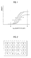
- Fig. 1 is a view showing one example of the characteristic curve of the silver halide light-sensitive material for the color filter prepared according to the present invention.
- Fig. 2 is a view showing one embodiment of the master color filter used in the present invention.
- Fig. 3 is a view showing one embodiment of the color filter prepared according to the present invention.
- Fig. 4 is a view showing one embodiment of the layer structure of the silver halide light-sensitive material for the color filter prepared according to the present invention.
- the master color filter (a) may be manufactured using the above-described evaporation, dyeing, printing, pigment dispersion, electrodeposition or electrodeposition transfer of a resist, however, in the present invention, from the standpoint of convenience, a silver halide color light-sensitive material (the first silver halide color light-sensitive material) comprising a light-transmittable support having thereon coatings, such as a commercially available color negative film, a color positive film for movies, a color reversal film, a color autopositive (color direct positive) film, a color intermediate film and a light-sensitive material by the silver dye bleaching process, is used.
- a silver halide color light-sensitive material comprising a light-transmittable support having thereon coatings, such as a commercially available color negative film, a color positive film for movies, a color reversal film, a color autopositive (color direct positive) film, a color intermediate film and a light-sensitive material by the silver dye bleaching process, is used.
- the silver halide light-sensitive material (b) (the second silver halide color light-sensitive material) which will be described below may also be used.
- the light-sensitive material used for the purpose of manufacturing the master color filter (a) is not limited in the color sensitivity to the combination of blue sensitivity, green sensitivity and red sensitivity, but combination with ultraviolet sensitivity, yellow sensitivity or infrared sensitivity may be used and a plurality of infrared sensitivities different in the sensitive wavelength region may also be used.
- the above-described silver halide color light-sensitive material for master color filter typically comprises a yellow coupler-containing silver halide emulsion layer, a magenta coupler-containing silver halide emulsion layer and a cyan coupler-containing silver halide emulsion layer.
- the construction may be such that the yellow coupler-containing silver halide emulsion layer has color sensitivity in the blue spectral region, the magenta coupler-containing silver halide emulsion layer has color sensitivity in the green spectral region and the cyan coupler-containing silver halide emulsion layer has color sensitivity in the red spectral region.
- An infrared dye-forming coupler is incorporated into the magenta coupler-containing silver halide emulsion layer, the yellow coupler-containing silver halide emulsion layer or both of these silver halide emulsion layers, or a silver halide emulsion layer having the same color sensitivity as the color sensitivity of either the magenta coupler-containing silver halide emulsion layer or the yellow coupler-containing silver halide emulsion layer or having color sensitivity in both spectral regions of these layers is separately provided and an infrared dye-forming coupler is incorporated into the layer.
- Preferred infrared dye-forming couplers for use in the present invention are those having a peak wavelength at from 700 nm to 1,100 nm in the light absorption spectrum upon color formation by the color development processing.
- the infrared dye-forming coupler is preferably a compound represented by the following formula (I): wherein L represents -CO- or -SO 2 -, R 1 represents an alkyl group, an aryl group or a heterocyclic group, R 2 represents a hydrogen atom, an alkyl group or an aryl group, R 3 represents a substituent, n represents 0, 1, 2, 3 or 4, and X represents a hydrogen atom or a group capable of splitting off upon coupling with an oxidation product of the developing agent.
- R 1 , R 2 , R 3 , n and X are described in detail below.
- R 1 represents an alkyl group, an aryl group or a heterocyclic group.
- the alkyl group is a substituted or unsubstituted linear, branched or cyclic alkyl group.
- the unsubstituted alkyl group is an unsubstituted linear, branched or cyclic alkyl group having from 1 to 36, preferably from 1 to 24, carbon atoms (e.g., methyl, ethyl, propyl, butyl, pentyl, hexyl, heptyl, octyl, decyl, dodecyl, tetradecyl, hexadecyl, octadecyl, isopropyl, t-butyl, 2-ethylhexyl, cyclohexyl, adamantyl).
- substituent in the substituted alkyl group examples include a halogen atom (e.g., fluorine, chlorine, bromine), a hydroxy group, a carboxyl group, a cyano group, a nitro group, an aryl group (having from 6 to 24, preferably from 6 to 14, carbon atoms, e.g., phenyl, naphthyl), an alkoxy group (having from 1 to 36, preferably from 1 to 24, carbon atoms, e.g., methoxy, ethoxy, propoxy, butoxy, hexyloxy, octyloxy, dodecyloxy, tetradecyloxy, hexadecyloxy, octadecyloxy, isopropoxy, 2-ethylhexyloxy, cyclohexyloxy), an aryloxy group (having from 6 to 36, preferably from 6 to 14, carbon atoms, e.g., flu
- the substituent in the substituted alkyl group is preferably a halogen atom, a cyano group, a carboxyl group, a hydroxy group, an alkoxy group, an aryloxy group, an alkylthio group, an arylthio group, a carbamoyl group, an amido group, an oxycarbonyl group, a carbonyloxy group, an oxycarbonylamido group, a carbamoylamino group, a sulfonamido group, a sulfamoyl group, a sulfonyl group or an imido group.
- the substituent in the substituted alkyl group is more preferably a halogen atom, a cyano group, an alkoxy group, an aryloxy group, a carbamoyl group, an amido group, an oxycarbonyl group, a carbonyloxy group, an oxycarbonylamido group, a carbamoylamino group, a sulfonamido group, a sulfamoyl group, a sulfonyl group or an imido group.
- substituents may further have a substituent.
- the substituted alkyl group may have a plurality of substituents and when two or more substituents are present, they may be the same or different.
- the aryl group is a substituted or unsubstituted aryl group.
- substituent in the substituted aryl group include the substituents described above as the substituent in the substituted alkyl group represented by R 1 and an alkyl group.
- a substituted aryl group is preferred and the substituent is preferably a halogen atom, a cyano group, an alkyl group, an aryl group, a heterocyclic group, an alkoxy group, an aryloxy group, a heterocyclic oxy group, an alkylthio group, an arylthio group, a carbonyloxy group, a carbamoyloxy group, an oxycarbonyl group, a carbamoyl group, an amino group, an acylamino group, an oxycarbonylamino group, a carbamoylamino group, a sulfonamido group, a sulfamoylamino group, an imido group, a sulfonyl group or a sulfamoyl group, more preferably, a halogen atom, a cyano group, an alkyl group, an aryl group, an alkoxy group, an aryloxy group
- the heterocyclic group is a 5-, 6- or 7-membered heterocyclic ring containing at least one of a nitrogen atom, an oxygen atom and a sulfur atom (e.g., pyrazolyl, imidazolyl, oxazolyl, thiazolyl, pyridyl, pyrimidyl, triazolyl, tetrazolyl, benzoxazolyl).
- the heterocyclic group may further be substituted by a substituent described above for the substituted alkyl group represented by R 1 or by an alkyl group.
- R 2 represents a hydrogen atom, an alkyl group or an aryl group, and the alkyl group and the aryl group have the same meanings as the alkyl group and the aryl group described above for R 1 , respectively.
- R 2 is preferably a hydrogen atom.
- R 3 represents a substituent, and n represents 0 or an integer of from 1 to 4.
- the substituent represented by R 3 includes the substituents described above for the substituted alkyl group represented by R 1 and an alkyl group.
- the substituent represented by R 3 is preferably a halogen atom, a hydroxy group, a cyano group, an alkyl group, an aryl group, a heterocyclic group, an alkoxy group, an aryloxy group, an alkylthio group, an arylthio group, a carbonyloxy group, an oxycarbonyl group, an acylamino group, an oxycarbonylamino group, a carbamoylamino group, a sulfonamido group, a sulfamoyl group, a sulfonyl group or an imido group, more preferably a halogen atom, an alkoxy group, an oxycarbonyl group, an acylamin
- n is preferably 0 or 1.
- X represents a hydrogen atom or a group capable of splitting off upon coupling with an oxidation product of the developing agent.
- the group capable of splitting off upon coupling with an oxidation product of the developing agent include a halogen'atom (e.g., fluorine, chlorine, bromine, iodine), a heterocyclic group or imido group which splits off by a nitrogen atom (e.g., splitting-off groups described in JP-A-56-38044, JP-B-58-10739 (the term "JP-B” as used herein means an "examined Japanese patent publication"), JP-B-56-54134 and JP-B-56-45135), an alkylthio group (e.g., splitting-off groups described in JP-A-56-126833), an arylthio group (e.g., splitting-off groups described in U.S.
- halogen'atom e.g., fluorine, chlorine, bromine, iodine
- Patent 4,351,897, JP-A-2-160233 an alkoxy group (e.g., splitting-off groups described in European Patent 423727), an aryloxy group (e.g., splitting-off groups described in European Patents 428902 and 299726), splitting-off groups described in U.S. Patent 4,072,525, JP-A-5-34878, JP-A-5-313322, European Patent 514896, JP-A-6-34796 and JP-A-7-48376, a carbonyloxy group and a carbamoyloxy group.
- an alkoxy group e.g., splitting-off groups described in European Patent 423727
- an aryloxy group e.g., splitting-off groups described in European Patents 428902 and 299726
- X is preferably a hydrogen atom, a halogen atom, an alkoxy group, an aryloxy group, an alkylthio group, an arylthio group, an imido group, a carbonyoxy group or a carbamoyloxy group, more preferably a hydrogen atom, a halogen atom (e.g., fluorine, chlorine), an alkoxy group, a carbonyloxy group or a carbamoyloxy group, and most preferably a hydrogen atom, a fluorine atom, a chlorine atom, an alkoxy group or a carbamoyloxy group.
- L represents -CO- or -SO 2 -, with -CO- being preferred.
- the coupler represented by formula (I) preferably has a structure represented'by the following formula (II): wherein R 4 has the same meaning as R 1 , R 5 represents an acyl group, an oxycarbonyl group, a carbamoyl group or a sulfonyl group, and X 1 has the same meaning as X.
- R 5 is described in detail below.
- R 5 represents an acyl group, an oxycarbonyl group, a carbamoyl group or a sulfonyl group.
- the acyl group is an acyl group having from 2 to 48, preferably from 2 to 24, carbon atoms (e.g., acetyl, propionyl, 2-ethylhexanoyl, isopropionyl, pivaloyl, octanoyl, decanoyl, tetradecanoyl, hexadecanoyl, cyclohexanoyl, benzoyl, trifluoroacetyl, 4-methylbenzoyl, 2-methoxybenzoyl, 2,5-dichlorobenzoyl, 2-methanesulfonamidobenzoyl, 4-t-butylbenzoyl, 2-(2,4-di-t-amylphenoxy)hexanoyl, 3-tetradecyloxycarbony
- R 5 is preferably an acyl group, an oxycarbonyl group or a carbamoyl group, more preferably an acyl group or an oxycarbonyl group.
- the amount of the infrared dye-forming coupler for use in the present invention is not particularly limited, however, it is preferably from 0.01 to 1.00 g/m 2 .
- the infrared dye-forming coupler may be added to any layer of the light-sensitive material, however, the color sensitivity of silver halide needs be adjusted so that the infrared dye is contained at least in a red image picture area formed when the light-sensitive material is developed, because out of red, green and blue, red transmits near infrared light most. Therefore, the infrared dye-forming coupler is added to the same layer as the magenta coupler and/or the yellow coupler or to the same layer as the silver halide emulsion layer having the same color sensitivity as these couplers.
- the infrared dye-forming coupler may be used together with a silver halide emulsion having color sensitivity different from yellow, magenta and cyan respective couplers and subjected to superposition exposure at the time of exposure of the light-sensitive material to thereby form an infrared dye in the red image picture area.
- the infrared dye may be formed, if desired, in the green, blue, black or other image picture area.
- the above-described silver halide color light-sensitive material (the first silver halide color light-sensitive material) is subjected to pattern exposure by fluorescent tube, CRT, plasma, light emitting diode (LED) or laser as a light source according to digital signals programmed so that red, green and blue colors can be formed, the black matrix area can be substantially colorless and a pixel pattern in the shape required can be obtained.
- a laser ray is preferred because the light spot size can be reduced and a high-precision pattern can be written at high speed.
- the black matrix area is substantially colorless
- the quantity of light necessary for forming sufficiently black color in the black matrix area can be obtained when the silver halide light-sensitive material (b) for color filter is exposed to white light through the master color filter (a) manufactured, and the area may be colored to gray or other color for controlling the quantity of light (excessive quantity of light causes blur and the pattern obtained becomes poor in the edge sharpness).
- the exposure pattern namely, the pixel pattern of the master color filter (a) can be easily varied by performing digital exposure using at least three laser light sources.
- the laser may be selected from various gas lasers, liquid lasers, solid lasers, semiconductor lasers and semiconductor diodes, according to the color sensitivity of the light-sensitive material used.
- the exposure may also be performed using a wavelength conversion element obtained by combining a nonlinear optical material and a coherent light source such as laser ray.
- the term "nonlinear optical element" as used herein means a material capable of giving nonlinearity between the polarization and the electric field appeared upon application of a strong photoelectric field such as laser rays.
- this material include an inorganic compound such as lithium niobate, potassium dihydrogenphosphate (KDP), lithium iodate and BaB 2 O 4 , a urea derivative, a nitroaniline derivative, a nitropyridine-N-oxide derivative such as 3-methyl-4-nitropyridine-N-oxide (POM), and the compounds described in JP-A-61-53462 and JP-A-62-210432.
- the wavelength conversion element is known to have the monocrystal optical waveguide path form or the fiber form and either is useful.
- the exposure method and exposure apparatus which can be used in the present invention are described in JP-A-2-129625, JP-A-5-176144, JP-A-5-199372, JP-A-6-127021, JP-A-7-15593, JP-A-7-140567, JP-A-7-248549, JP-A-7-248541, JP-A-7-295115, JP-A-7-290760, JP-A-7-301868, JP-A-7-301869, JP-A-7-306481 and JP-A-8-15788.
- Various commercially available laser exposure apparatuses can of course be used.
- the silver halide color light-sensitive material after the above-described pattern exposure is processed according to the known normal development processing and thereby, a master color filter (a) colored to red, green and blue and having a substantially colorless black matrix area is obtained.
- the silver halide color light-sensitive material (b) for (the second silver halide color light-sensitive material) color filter for use in the present invention is a silver halide color light-sensitive material comprising a transparent substrate having thereon at least a red-sensitive silver halide emulsion layer containing a coupler having sensitivity to the red of the master color filter (a) and forming a red color, a green-sensitive silver halide emulsion layer containing a coupler having sensitivity to the green of the master color filter (a) and forming a green color, a blue-sensitive silver halide emulsion layer containing a coupler having sensitivity to the blue of the master color filter (a) and forming a blue color, and an infrared-sensitive emulsion.
- the coupler which forms a red color may be a combination of a yellow coupler with a magenta coupler or a red coupler capable of solely forming a red color.
- the coupler which forms a green color may be a combination of a yellow coupler with a cyan coupler or a green coupler capable of solely forming a green color.
- the coupler which forms a blue color may be a combination of a cyan coupler with a magenta coupler or a coupler capable of solely forming a blue color.
- the silver halide light-sensitive material (b) for color filter used in the present invention a material having a characteristic curve shown in Fig. 1 is used, the blue-sensitive emulsion layer contains a cyan coupler and a magenta coupler (or contains a blue coupler), the green-sensitive emulsion layer contains a yellow coupler and a cyan coupler (or contains a green coupler), and the red-sensitive emulsion layer contains a yellow coupler and a magenta coupler (or contains a red coupler).
- the blue-sensitive emulsion layer contains a cyan coupler and a magenta coupler (or contains a blue coupler)
- the green-sensitive emulsion layer contains a yellow coupler and a cyan coupler (or contains a green coupler)
- the red-sensitive emulsion layer contains a yellow coupler and a magenta coupler (or contains a red coupler).
- symbol "a” corresponds to a red-sensitive emulsion
- symbol “b” corresponds to a green-sensitive emulsion
- symbol “c” corresponds to a blue-sensitive emulsion
- symbol “d” corresponds to an infrared-sensitive emulsion.
- This silver halide light-sensitive material for color filter is exposed to blue, green, red and white lights using a master color filter as shown in Fig. 2 having a pattern in a density capable of giving exposure at the positions of point A and point B in Fig. 1.
- the background area is substantially colorless and transparent, but may be colored to gray or other color for controlling the quantity of light.
- the light-sensitive material is subjected to color development, desilvering (bleach-fixing) and water washing and then a color filter having formed thereon blue, green and red colors as shown in Fig. 3 is obtained.
- the background area is black.
- Fig. 4 shows another embodiment of the layer structure of the silver halide light-sensitive material (b) for color filter used in the present invention.
- reference numeral 1 represents a protective layer
- reference numeral 2 represents an antihalation layer
- reference numeral 3 represents a support.
- a coupler in the same system can be added to a layer adjacent to each silver halide emulsion layer, therefore, color mixing of dyes between respective emulsion layers can be restrained even without the interposition of an interlayer and the color filter can be reduced in the thickness.
- an interlayer can be disposed between emulsion layers having different color sensitivities and in this case, the amount of the color mixing inhibitor added can be reduced.
- the silver halide light-sensitive material is, in the same manner as above, exposed using a master color filter as shown in Fig. 2 and then subjected to color development, bleach-fixing and water washing.
- the silver halide emulsion layers different in the color sensitivity each is constituted by at least two unit layers.
- the unit layers having the same color sensitivity may be different or the same in the sensitivity.
- These two unit layers each contains at least one coupler such that the hues formed are different between layers.
- the order of providing three silver halide emulsion layers having color sensitivity to red, green or blue is not limited to the order above but may be freely selected.
- a subbing layer, an interlayer, a yellow filter layer capable of bleaching, a protective layer or an ultraviolet absorbing layer may be provided, if desired.
- the master color filter (a) when one-shot exposure with white light is performed, in the case of equal magnification, the master color filter (a) is placed close to or in contact with the silver halide light-sensitive material (b) for color filter and the binder layers of these two light-sensitive materials face each other.
- the master color filter (a) may be improved in the adhesion or blur when it is exposed in the state such that the surface on the support side is laminated with a rigid transparent material such as glass or a load such as glass is imposed thereon.
- the pixel pattern of the master color filter (a) may be enlarged or reduced to a similitude by means of a camera for the photomechanical process and exposed on a silver halide light-sensitive material (b) for color filter.
- a pixel pattern of the master color filter (a) is formed larger than the desired size and reduced upon printing, the color filter obtained has a pattern of higher precision and the digital exposure by laser or the like is advantageously facilitated.
- a color correction filter of various types or an ND (Neutral Density) filter may be interposed between the white light source and the master color filter (a) on exposure.
- the silver halide grain which can be used in the silver halide light-sensitive material (b) for color filter of the present invention includes silver chloride, silver bromide, silver iodochloride, silver chlorobromide and silver iodochlorobromide.
- the silver chloride content is preferably 50 mol% or more, more preferably 80 mol% or more.
- the silver iodide content is preferably 2 mol% or less, more preferably 1 mol% or less, still more preferably 0.5 mol% or less.
- the silver halide emulsion for use in the present invention may be a homogeneous crystal structure grain or a multiple structure grain having different halogen compositions between the inside of the grain and the surface of the grain. Further, silver halide having a different composition may be joined to the grain by epitaxial conjunction. Furthermore, a compound other than silver halide, such as silver rhodanate or lead oxide, may be joined thereto.
- the high silver chloride emulsion for use in the present invention may have a structure such that a stratified or non-stratified silver bromide localized phase is present in the inside and/or surface of silver halide.
- the halogen composition in the localized phase preferably has a silver bromide content of at least 20 mol%, more preferably in excess of 30 mol%.
- the silver bromide content in the silver bromide localized phase can be analyzed by the X-ray diffraction method.
- the application method of the X-ray diffraction method to silver halide grains is described in, for example, C.R. Berry and S.J. Marino, Photographic Science and Technology , Vol. 2, p. 149 (1955), and ibid.
- the silver bromide localized phase may be present in the inside of a grain, or at the edge or corner of or on the plane of the grain surface, however, it is preferably joined to the corner part of a grain by epitaxial conjunction.
- the average grain size of silver halide grains for use in the present invention is preferably from 0.05 to 0.9 ⁇ m, more preferably from 0.1 to 0.5 ⁇ m.
- the thickness is preferably from 0.05 to 0.9 ⁇ m, more preferably from 0.1 to 0.5 ⁇ m.
- a monodisperse emulsion having a narrow grain size distribution may also be used.
- the monodisperse emulsion is a silver halide emulsion, for example, having a grain size distribution such that 80% or more by number or weight of all grains have a size falling within the average grain size ⁇ 30%.
- a monodisperse silver halide emulsion having a coefficient of variation of 20% or less, preferably 15% or less, may be used.
- a polydisperse emulsion having a wide grain size distribution may also be used.
- the silver halide emulsion which can be used in the present invention may be prepared by the method described, for example, in Research disclosure (RD) "I. Emulsion Preparation and Types", Vol. 176, No. 17643, pp. 22-23 (December, 1978), ibid. , No. 18716, p. 648 (November, 1979), P. Glafkides, Chimie et Physique Photographique , Paul Montel (1967), G.F. Duffin, Photographic Emulsion Chemistry , the Focal Press (1966), and V.L. Zelikman et al, Making and Coating Photographic Emulsion, the Focal Press (1964).
- RD Research disclosure
- a tabular grain having an aspect ratio of about 5 or more may also be used in the present invention.
- the tabular grain may be easily prepared by the methods described in Gutoff, Photographic Science and Engineering , Vol. 14, pp. 248-257 (1970), U.S. Patents 4,434,226, 4,414,310, 4,433,048 and 4,439,520, and British Patent 2,112,157.
- a mixture of grains having various crystal forms may also be used.
- the light-sensitive silver halide emulsion is usually a silver halide emulsion subjected to chemical sensitization.
- the chemical sensitization of the light-sensitive silver halide emulsion for use in the present invention may be performed by chalcogen sensitization such as sulfur sensitization, selenium sensitization and tellurium sensitization, noble metal sensitization using gold, platinum or palladium, or reduction sensitization, which are known to the emulsion for normal light-sensitive materials, and these sensitization methods may be used individually or in combination (see, for example, JP-A-3-110555 and Japanese Patent Application No. 4-75794).
- the chemical sensitization may also be performed in the presence of a nitrogen-containing heterocyclic compound (see, JP-A-62-253159). Further, an antifoggant which will be described later may be added after completion of the chemical sensitization. More specifically, the methods described in JP-A-5-45833 and JP-A-62-40446 may be used.
- the pH is preferably from 5.3 to 10.5, more preferably from 5.5 to 8.5, and the pAg is preferably from 6.0 to 10.5, more preferably from 6.8 to 9.0.
- the coating amount of the light-sensitive silver halide emulsion for use in the present invention is from 1 mg/m 2 to 10 g/m 2 as calculated in terms of silver.
- the light-sensitive silver halide emulsion for use in the present invention is subjected to spectral sensitization with a methine dye or the like so that the light-sensitive silver halide can have color sensitivity to green, red or infrared. Further, the blue-sensitive emulsion may be subjected to spectral sensitization in the blue region, if desired.
- the dye which can be used includes cyanine dyes, merocyanine dyes, complex cyanine dyes, complex merocyanine dyes, holopolar cyanine dyes, hemicyanine dyes, styryl dyes and hemioxonol dyes.
- sensitizing dyes may be used individually or in combination thereof, and the combination of sensitizing dyes is often used for the purpose of supersensitization or for controlling the wavelength of spectral sensitivity.
- a dye which itself has no spectral sensitization effect, or a compound which absorbs substantially no visible light, but which exhibits supersensitization may be incorporated into the emulsion (for example, those described in U.S. Patent 3,615,641 and JP-A-63-23145).
- the sensitizing dye may be added to the emulsion before, during or after chemical ripening, or may be added before or after nucleation of silver halide grains according to U.S. Patents 4,183,756 and 4,225,666.
- the sensitizing dye or supersensitizer may be added as a solution of an organic solvent such as methanol, a dispersion of gelatin or a solution of a surface active agent. The amount added is in general on the order of from 10 -8 to 10 -2 mol per mol of silver halide.
- the color developing agent which can be used in the present invention may be sufficient if the oxidation product of the developing agent formed on the development of silver halide makes coupling reaction with a coupler to form a dye and such a color developing agent is known in the photographic field.
- Specific examples of the color developing agent are described in T.H. James, The Theory of the Photographic Process , 4th ed., pp. 291-334 and pp. 353-361.
- a particularly preferred color developing agent is a p-phenylenediamine derivative.
- the color developing agents described in JP-A-8-254610 and JP-A-7-333107 can also be used.
- a two-equivalent coupler substituted by a splitting-off group is preferred more than a four-equivalent color coupler having a hydrogen atom at the active site because the coated silver amount can be reduced.
- a representative example of the yellow coupler which can be used in the present invention is an oil protect-type acylacetamide-base coupler. Specific examples thereof are described in U.S. Patents 2,407,210, 2,875,057 and 3,265,506.
- a two-equivalent yellow coupler is preferably used and representative examples thereof include oxygen atom-releasing yellow couplers described in U.S. Patents 3,408,194, 3,447,928, 3,935,501 and 4,022,620, and nitrogen atom-releasing yellow couplers described in JP-B-58-10739, U.S.
- OLS West German Patent Publication
- the ⁇ -pivaloylacetanilide-base coupler is excellent in the fastness, particularly light fastness, of the colored dye, whereas the ⁇ -benzoylacetanilide-base coupler can provide a high color density.
- the magenta coupler which can be used in the present invention includes oil protect-type, preferably, 5-pyrazolone-base couplers and pyrazoloazole-base couplers such as pyrazolotriazoles.
- the 5-pyrazolone-base coupler is preferably substituted by an arylamino group or an acylamino group at the 3-position in view of hue and color density of the colored dye. Representative examples thereof are described in U.S. Patents 2,311,082, 2,343,703, 2,600,788, 2,908,573, 3,062,653, 3,152,896 and 3,936,015.
- the splitting-off group of the two-equivalent 5-pyrazolone-base coupler is particularly'preferably the nitrogen atom splitting-off group described in U.S. Patent 4,310,619 or the arylthio group described in U.S. Patent 4,351,897.
- the 5-pyrazolone-base coupler having a ballast group described in European Patent 73,636 can provide a high
- the pyrazoloazole-base coupler includes pyrazolobenzimidazoles described in U.S. Patent 3,369,879, preferably pyrazolo[5,1-c][1,2,4]triazoles described in U.S. Patent 3,725,067, pyrazolotetrazoles described in Research Disclosure , No. 24220 (June, 1984), and pyrazolopyrazoles described in Research Disclosure , No. 24230 (June, 1984).
- imidazo[1,2-b]pyrazoles described in European Patent 119,741 are preferred, and pyrazolo[1,5-b][1,2,4]triazole described in European Patent 119,860 is particularly preferred.
- the cyan coupler which can be used in the present invention includes naphthol-base couplers described in U.S. Patents 2,474,293, 4,052,212, 4,146,396, 4,228,233 and 4,296,200, phenolic cyan couplers having an alkyl group of ethyl or greater group at the meta-position of the phenol nucleus described in U.S. Patent 3,772,002, 2,5-diacylamino-substituted phenolic couplers described in U.S. Patents 2,772,162, 3,758,308, 4,126,396, 4,334,011 and 4,327,173, West German Patent Publication (OLS) No.
- Typical examples of the dye forming polymer coupler are described in U.S. Patents 3,451,820, 4,080,211 and 4,367,282, and British Patent 2,102,173.
- Examples of the coupler which solely forms a red color includes the red polymer coupler obtained by copolymerizing a yellow coupler component and a magenta coupler component described in JP-A-9-189986.
- Examples of the coupler which solely forms a green color include the green polymer coupler obtained by copolymerizing a yellow coupler component with a cyan coupler component described in JP-A-9-204026.
- Examples of the coupler which solely form a blue color include the blue polymer coupler obtained by copolymerizing a cyan coupler component and a magenta coupler component described in JP-A-9-204027.
- a coupler which releases a photographically useful residue upon coupling is also preferably used in the present invention.
- Preferred examples of the DIR coupler which releases a development inhibitor are described in patents cited in RD, No. 17643, Item VII-F, JP-A-57-151944, JP-A-57-154234, JP-A-60-184248 and U.S. Patent 4,248,962.
- couplers which can be used in the light-sensitive material for use in the present invention include competitive couplers described in U.S. Patent 4,130,427, polyequivalent couplers described in U.S. Patents 4,283,472, 4,338,393 and 4,310,618, DIR redox compound-releasing couplers described in JP-A-60-185950, and couplers which release a dye capable of recovering the color after being released described in European Unexamined Patent Publication 173,302A.
- the equivalent ratio of the coupler to silver halide in each silver halide emulsion layer is preferably from 1 to 3.
- the equivalent ratio is preferably from 1 to 2.
- the term "equivalent ratio" as used herein has meaning such that assuming that the theoretical amount of silver halide necessary for all couplers to form a color is an equivalent ratio of 1, when silver halide is coated in an amount of, for example, two times the theoretical amount, the equivalent ratio is 2. In other words, when a 2-equivalent coupler is used and the coated silver amount is 2 mols based on 1 mol of the coupler, the equivalent ratio is 1, and when the coated silver amount is 4 mol, the equivalent ratio is 2.
- the coupler for use in the present invention may be incorporated into the light-sensitive material by various known dispersion methods.
- the high boiling point solvent for use in the oil-in-water dispersion method are described in U.S. Patent 2,322,027.
- the amount of the high boiling point solvent is 10 g or less, preferably 5 g or less, more preferably from 0.01 to 1 g, per g of the coupler, and 2 g or less, preferably 1 g or less, more preferably 0.5 g or less, per g of the binder.
- the size of the coupler dispersion (coupler emulsified product) obtained by the oil-in-water dispersion method is from 0.05 to 0.9 ⁇ m, preferably from 0.1 to 0.5 ⁇ m.
- the coupler-containing layer preferably uses a dye image preservability improving compound described in European Unexamined Patent Publication EP0,277,589A2. In particular, it is preferably used in combination with a pyrazoloazole-base magenta coupler.
- Compound (F) which reacts with the aromatic amine-base developing agent remaining after color development to produce a chemically inactive and substantially colorless compound and/or Compound (G) which reacts with an oxidation product of the aromatic amine-base developing agent remaining after color development to produce a chemically inactive and substantially colorless compound are preferably used simultaneously or individually, for example, for preventing staining or other side reaction due to a colored dye produced by the reaction of the color developing agent or oxidation product thereof remaining in the layer with a coupler during storage after the processing.
- the silver halide emulsion layer or interlayer of the light-sensitive material for use in the present invention may contain a hydroquinone derivative, an aminophenol derivative, a gallic acid derivative or an ascorbic acid derivative as an antifoggant or a color mixing inhibitor.
- a hydroquinone derivative an aminophenol derivative, a gallic acid derivative or an ascorbic acid derivative as an antifoggant or a color mixing inhibitor.
- preferred are those which hardly generate stains even upon heating at from 160 to 200°C.
- Examples of the ultraviolet absorbent include benzotriazole compounds substituted by an aryl group (for example, those described in U.S. Patent 3,533,794), 4-thiazolidone compounds (for example, those described in U.S. Patents 3,314,794 and 3,352,681), benzophenone compounds (for example, those described in JP-A-46-2784), cinnamic ester compounds (for example, those described in U.S. Patents 3,705,805 and 3,707,395), butadiene compounds (for example, those described in U.S. Patent 4,045,229) and benzoxazole compounds (for example, those described in U.S. Patents 3,406,070 and 4,271,307).
- benzotriazole compounds substituted by an aryl group for example, those described in U.S. Patent 3,533,794
- 4-thiazolidone compounds for example, those described in U.S. Patents 3,314,794 and 3,352,681
- benzophenone compounds for example,
- An ultraviolet light absorbing coupler e.g., ⁇ -naphthol-base cyan dye forming coupler
- an ultraviolet absorbing polymer may also be used.
- the ultraviolet absorbent may be mordanted to a specific layer.
- the benzotriazole compound substituted by an aryl group is preferred.
- an antifungal or antiseptic as described in JP-A-63-271247 is preferably added so as to prevent various molds and bacteria from proliferation in the hydrophilic colloid layer to deteriorate the image.
- Gelatin is advantageous as the binder or protective colloid which can be used in the silver halide emulsion layer, the interlayer or the protective layer of the light-sensitive material for use in the present invention, however, other hydrophilic polymers may also be used.
- the hydrophilic polymer include polyvinyl alcohol, polyvinyl alcohol partial acetal, polyvinyl butyral, poly-N-vinylpyrrolidone, polyacrylic acid, polyacrylamide, polyvinylimidazole, polyvinylpyrazole, carrageenan, gum arabi and a homopolymer or copolymer of cellulose derivatives such as hydroxyalkyl cellulose, carboxymethyl cellulose, cellulose sulfate, cellulose acetate hydrogen phthalate and sodium alginate.
- a graft polymer of gelatin with other polymer may be used and examples of the gelatin graft polymer include those obtained by grafting an acrylic acid, a methacrylic acid, a derivative such as ester or amide of the acrylic acid or methacrylic acid, or a homopolymer or copolymer of vinyl-base monomers such as acrylonitrile or styrene, to gelatin.
- graft polymers to a polymer having somewhat compatibility with gelatin such as a polymer of acrylic acid, methacrylic acid, acrylamide, methacrylamide or hydroxyalkyl methacrylate, are preferred. Examples thereof are described in U.S. Patents 2,763,625, 2,831,767 and 2,956,884, and JP-A-56-65133.
- hydrophilic polymers may be used either individually or in combination of two or more thereof.
- the gelatin may be an alkali-processed gelatin, an acid-processed gelatin, an enzyme-processed gelatin or a mixture of these.
- a gelatin derivative obtained by reacting various compounds such as an acid halide, an acid anhydride, an isocyanate, a bromoacetic acid, an alkanesultone acid, a vinylsulfonamide, a maleinimide compound, a polyalkylene oxide or an epoxy compound, with gelatin may also be used.
- Specific examples of the gelatin derivative are described in U.S. Patents 2,614,928, 3,132,945, 3,186,846 and 3,312,553, British Patents 861,414, 1,033,189 and 1,005,784, and JP-B-42-26845.
- the total binder amount in the light-sensitive material for use in the present invention is preferably from 3 to 10 g/m 2 , and the amount of binder contained in each silver halide emulsion layer or interlayer is preferably from 0.1 to 1.5 g/m 2 , more preferably from 0.2 to 1.0 g/m 2 .
- the support for use in the present invention is preferably a light-transmitting substrate, however, as described in JP-A-7-244212, silver halide emulsion layers provided on a separate support may be transferred and firmly bonded onto a light-transmitting substrate to prepare a light-sensitive material for color filter.
- the support is not necessarily required to be light-transmitting and for example, a support having coated on the back surface thereof carbon black or the like may be used.
- the binder in the release layer or back layer provided is not counted in the above-described "total binder amount”.
- the material constituting the light-transmitting substrate preferably has an optically isotropic property and excellent heat resistance and examples thereof include polyethylene terephthalate, polybutylene terephthalate, polyethylene naphthalate, polystyrene, polycarbonate, polyether sulfone, cellulose acetate, polyarylate, soda glass, borosilicate glass and quartz.
- the surface of the substrate constituted by the above-described material may be subjected to undercoating treatment, if desired. Further, the surface may be subjected to glow discharge, corona discharge or ultraviolet (UV) irradiation treatment.
- undercoating treatment if desired.
- the surface may be subjected to glow discharge, corona discharge or ultraviolet (UV) irradiation treatment.
- UV ultraviolet
- the light-transmitting substrate may be used in the form of a plate, a sheet or a film.
- the thickness of the substrate may be appropriately selected depending upon the use and the construction material, however, it is commonly from 0.01 to 10 mm. For example, in the case of a glass substrate, the thickness is from 0.3 to 3 mm.
- the light-sensitive material for use in the present invention is subjected to color development by the usual methods described in RD, No. 17643, pp. 28-29 and ibid. , No. 18716, p. 651, left to tight columns, to obtain a microcolor filter.
- the light-sensitive material is subjected to color development, desilvering and water washing.
- bleach-fixing processing using a bleach-fixing solution may be performed in place of bleaching using a bleaching solution and fixing using a fixing solution, or bleaching, fixing and bleach-fixing may be combined in any order.
- Stabilization may be performed in place of water washing, or stabilization may be performed after water washing.
- mono-bath processing using a mono-bath developing-bleaching-fixing processing solution capable of conducting color development, bleaching and fixing in one bath may also be performed.
- pre-hardening processing, neutralization processing therefor, stop-fixing processing, after-hardening processing, regulating or intensification may be performed.
- so-called activator processing may be performed in place of color development processing.
- a developing machine used in usual photographic processing may be used.
- a developing machine for glass dry plate or a developing apparatus described in JP-A-7-56015 may be used.
- a heat-resistant and water-proof resin having a high electric resistivity may be provided as an outermost protective layer (overcoat layer).
- the resin are described in U.S. Patents 4,171,979, 4,049,861, 4,333,998, 4,698,295 and 4,668,601, European Unexamined Patent Publications 179636A and 556810A, JP-A-3-163416, JP-A-3-188153, JP-A-5-78443, JP-A-1-276101, JP-A-2-179628, JP-A-5-19115, JP-A-5-173012, JP-A-5-264811, JP-A-60-216307, JP-A-63-218771, JP-A-52-22099, JP-A-52-22100, JP-A-53-142447, JP-A-54-137072, JP-A-54-83999, JP-A-55-125104, JP-A-5
- a transparent electrode may be provided by evaporation coating, for example, vacuum evaporation or sputtering.
- an orientating layer of polyimide resin or the like may be provided.
- a deflecting plate or plate difference film may be provided on the surface opposite to the emulsion surface side of the light-transmitting substrate of the color filter.
- a plastic film substrate having provided thereon a gas barrier layer or hard coat layer may be used as the light-transmitting substrate.
- a color positive film for movies "Fuji Color Positive Film CL” (produced by Fuji Photo Film Co., Ltd.) was subjected to digital exposure as shown in Fig. 2 from the emulsion surface thereof using an He-Cd laser (B light), a green semiconductor excited laser (using SHG) (G light) and an He-Ne laser (R light).
- Each RGB pixel had a size of 200 ⁇ m ⁇ 300 ⁇ m
- the black matrix (BM) area had a width of 25 ⁇ m
- the entire picture plane size was 24 cm ⁇ 16 cm.
- the exposed light-sensitive material was developed according to the formulation of ECP-2B processing issued by Eastman Kodak Company to manufacture a master color filter having formed thereon RGB colors.
- a process for manufacturing a color filter using the master color filter prepared is described below.
- Color Light-Sensitive Material 1A On a 100 ⁇ m-thick polyethylene terephthalate support having a back layer formed by coating carbon black dispersed in polyvinyl chloride, gelatin subbing was applied and thereon from the first to eighth layers each having the following structure were simultaneously coated one on another to prepare Color Light-Sensitive Material 1A.
- the components and the coated amounts (unit: g/m 2 ) are shown below. With respect to the silver halide, the coated amount is calculated in terms of silver.
- First Layer release layer: Hydroxyethyl cellulose (HEC-5P500; produced by Daicel Chemical KK) 0.35 Terminal alkyl-modified polyvinyl alcohol (average polymerization degree: 300) 0.08 Antistatic Agent (Cpd-1) 0.03 Second Layer (gelatin adjacent layer): Gelatin 0.60 Third Layer (blue-sensitive layer): Silver halide emulsion spectrally sensitized by Blue Sensitizing Dyes (ExS-1 and ExS-2) (AgBr 30 Cl 70 ; average grain size: 0.35 ⁇ m) 0.33 Gelatin 1.00 Cyan Coupler (ExC-2) 0.57 Magenta Coupler (ExM-3) 0.05 Ultraviolet Absorbent (Cpd-6) 0.03 Ultraviolet Absorbent (Cpd-7) 0.08 High Boiling Point Solvent (Solv-1) 0.23 Fourth Layer (interlayer): Gelatin 0.38 Color Mixing Inhibitor (Cpd-2) 0.02 Color Mixing Inhibitor (Cpd-10)
- sodium dodecylbenzenesulfonate as an emulsification dispersion aid
- ethyl acetate as an auxiliary solvent
- Surface Active Agent (Cpd-17) as a coating aid
- potassium polystyrenesulfonate as a thickening agent
- a 0.7 mm-thick transparent alkali-free glass (20 cm ⁇ 30 cm) was used as the light-transmitting substrate.
- a 1:3 (by weight) mixture of gelatin and colloidal silica (average particle size: 7 to 9 m ⁇ ) having added thereto saponin as a surface active agent was coated.
- the dry thickness of the layer formed was 0.2 ⁇ m.
- the protective layer of Color Light-Sensitive Material 1A prepared above was adhered onto the coated surface of the light-transmitting substrate.
- the laminate obtained was traveled at a linear velocity of 0.45 m/min in a laminator where the temperature was set so that the temperature on the contact surface could be about 130°C.
- the support of the light-sensitive material was peeled off together with the release layer from the emulsion surface. Then, second and upper emulsion layers were evenly bonded to the substrate and white spots were not observed.
- the thus-prepared substrate having emulsion layers was subjected to one-shot exposure from the emulsion surface side at an equal magnification or half (1/2) reduction through the master color filter prepared above using a camera for the photomechanical process.
- the exposed substrate was developed according to the following steps and as a result, a color filter having formed thereon BGR three colors and black color as shown in Fig. 3 in one operation was prepared. Processing Step Temperature (°C) Time Hardening 38 3 min. Water washing-1 35 1 min. Color development 38 80 s Stopping 38 20 s Bleach-fixing 38 90 s Water washing-2 35 40 s Water washing-3 35 80 s Drying 60 2 min.
- Each processing solution had the following composition.
- the stopping solution was an aqueous 2% acetic acid solution.
- Hardening Solution Sodium sulfate (anhydrous) 160.0 g Sodium carbonate (anhydrous) 4.6 g Glyoxal (40%) 50.0 ml Water to make 1 l pH (25°C) 9.5
- Color Developer Water 800 ml D-Sorbitol 0.15 g Sodium naphthalenesulfonate ⁇ formalin condensate 0.15 g Pentasodium nitrilotris (methylenephosphonate) 1.8 g Diethylenetriaminepentaacetic acid 0.5 g 1-Hydroxyethylidene-1,1-diphosphonic acid 0.15 g Diethylene glycol 12.0 ml Benzyl alcohol 13.5 ml Potassium chloride 6.5 g Potassium bromide 0.1 g Potassium carbonate 30.0 g Sodium sulfite 2.4
- an overcoat agent "SS5333/SS0333” produced by Nippon Synthetic Rubber KK was coated by means of a spinner to have a dry thickness of 2.5 ⁇ m, pre-heated at 120°C for 30 minutes and then baked at 180°C for 30 minutes to form a protective layer.
- An optically isotropic 80 ⁇ m-thick polyarylate substrate having laminated on the back surface thereof a polypropylene protective layer (20 ⁇ m) was subjected to glow discharge treatment and thereon two layers of an SBR latex layer and a gelatin layer were coated so as to improve adhesion to the photographic emulsion layer. Further thereon, from the first to ninth layers each having the following structure were simultaneously coated one on another to prepare Color Light-Sensitive Material 2A.
- the components and the coated amounts (unit: g/m 2 ) are shown below. With respect to the silver halide, the coated amount is calculated in terms of silver.
- First Layer Gelatin 0.70 Antihalation dye (fine particle dispersion) 0.17 Carboxymethyl cellulose 0.05 Surface Active Agent (Cpd-16) 0.03 Hardening Agent (H-1) 0.05 Second Layer (first red-sensitive layer): Silver halide emulsion spectrally sensitized by Red Sensitizing Dyes (ExS-4 and ExS-5) (AgCl; average grain size: 0.18 ⁇ m) 0.11 Gelatin 0.70 Magenta Coupler (ExM-1) 0.15 Discoloration Inhibitor (Cpd-3) 0.08 Discoloration Inhibitor (Cpd-5) 0.01 High Boiling Point Solvent (Solv-4) 0.28 High Boiling Point Solvent (Solv-5) 0.14 Polymer (Cpd-11) 0.08 Third Layer (second red-sensitive layer): Silver halide emulsion spectrally sensitized by Red Sensitizing Dyes (ExS-4 and ExS-5) (AgCl; average grain size: 0.18
- sodium dodecylbenzenesulfonate as an emulsification dispersion aid
- ethyl acetate as an auxiliary solvent
- Surface Active Agent (Cpd-17) as a coating aid
- potassium polystyrenesulfonate as a thickening agent
- Color Light-Sensitive Material 2A prepared above was subjected to contact exposure in one shot using the same master color filter as in Example 1 and then developed through the following steps. As a result, a color filter having formed thereon B, G, R three colors and black color in one operation was prepared.
- the processing solution were the same as those used in Example 1.
- the after-hardening solution was an aqueous 4% glutaraldehyde solution. Processing Step Temperature (°C) Time Color development 38 80 s Bleach-fixing 38 90 s Water washing-1 35 40 s After-hardening 35 3 min. Water washing-2 35 2 min. Drying 60 2 min.
- the following composition was coated to have a dry thickness of 2.5 ⁇ m, then dried and hardened with ultraviolet rays to form a protective layer.
- the resulting color filter was good in the adhesion between the color filter layer and the protective layer and had good resistance against chemicals.
- a color liquid crystal panel comprising a plastic film substrate was produced.
- Formulation of Overcoat Composition Monomer (1) 77.4 wt% Monomer (2) 7.7 Polymer CAB 531 (produced by Eastman Chemical) 11.7 Photopolymerization initiator 2.4 Sensitizer 0.8 Diluting solvent (MEK) for coating -
- a master color filter having any pixel pattern can be easily manufactured using a commercially available silver halide color light-sensitive material.
- a silver halide color light-sensitive material for color filter By subjecting a silver halide color light-sensitive material for color filter to one-shot exposure using this master color filter and then to one-time development processing, a color filter can be easily manufactured within a short time.
- the color filter obtained has red, green and blue color areas excellent in the spectral characteristics.
- PEN-1A described in Example 1 of JIII Journal of Technical Disclosure , No. 94-6023 was used and subjected to the surface treatment and then to gelatin subbing in the same manner to prepare color light-sensitive materials (3A, 3B, 4A, 4B) each having the following structure.
- the components and the coating amounts are shown below. With respect to the silver halide and colloidal silver emulsion, the coating amount is calculated in terms of silver.
- the silver halide emulsion in each layer is a negative silver chlorobromide or silver chloride.
- Second Layer (red-sensitive layer): Silver chloride spectrally sensitized by Red Sensitizing Dyes (ExS-4 and ExS-5) (average grain size: 0.18 ⁇ m) 0.90 Gelatin 2.68 Yellow Coupler (ExY-1) 1.22 Magenta Coupler (ExM-1) 0.30 Discoloration Inhibitor (Cpd-3) 0.16 Discoloration Inhibitor (Cpd-5) 0.02 Polymer (Cpd-11) 0.16 Stain Inhibitor (Cpd-13) 0.16 High Boiling Point Solvent (Solv-4) 0.53 High Boiling Point Solvent (Solv-5) 0.28 High Boiling Point Solvent (Solv-6) 0.48 Third Layer (interlayer): Gelatin 0.38 Color Mixing Inhibitor (Cpd-2) 0.38 Color Mixing Inhibitor (Cpd-2) 0.38 Color Mixing Inhibitor (Cpd-2) 0.38 Color Mixing Inhibitor (Cpd-2) 0.38 Color Mixing Inhibitor (
- sodium dodecylbenzenesulfonate as an emulsification dispersion aid
- ethyl acetate as an auxiliary solvent
- Surface Active Agent (Cpd-17) as a coating aid
- potassium polystyrenesulfonate as a thickening agent
- Color Light-Sensitive Material 3B was prepared by adding 0.30 g/m 2 of Infrared Dye-Forming Coupler (C-1) to the second layer (red-sensitive layer) of Color Light-Sensitive Material 3A.
- First Layer Gelatin 0.70 Colloidal silver emulsion (average grain size: 0.02 ⁇ m) 0.20 Second Layer (gelatin layer): Gelatin 0.50 Third Layer (red-sensitive layer): Silver chloride spectrally sensitized by Red Sensitizing Dyes (ExS-4 and ExS-5) (average grain size: 0.18 ⁇ m) 0.70 Gelatin 2.10 Cyan Coupler (ExC-2) 0.93 Ultraviolet Absorbent (Cpd-6) 0.20 Ultraviolet Absorbent (Cpd-7) 0.40 High Boiling Point Solvent (Solv-1) 0.93 Color mixing inhibitor (Cpd-2) 0.02 Compound (Cpd-12) 0.01 Fourth Layer (interlayer): Gelatin 0.53 Color Mixing Inhibitor (Cpd-10) 0.18 High Boiling Point Solvent (Solv-1) 0.05 High Boiling Point Solvent (Solv-2) 0.13 Irradiation Preventive Dye (Dye-1) 0.01 Irradiation Preventive Dye (Dye
- Color Light-Sensitive Material 4B was prepared by adding 0.24 g/m 2 of Infrared Dye-Forming Coupler (C-15) to the fifth layer (green-sensitive layer) and the seventh layer (blue-sensitive layer) of Color Light-Sensitive Material 4A.
- C-15 Infrared Dye-Forming Coupler
- Each of Color Light-Sensitive Materials 3A, 3B, 4A and 4B prepared above was subjected to digital exposure of a pattern as shown in Fig. 2 from the emulsion surface thereof using an He-Cd laser (B light), a green semiconductor excited laser (using SHG) (G light) and an He-Ne laser (R light) while controlling the quantity of light so as to obtain hues in agreement with the color sensitivity of BGR of the silver halide light-sensitive material for color filter which will be described later.
- Each RGB pixel had a size of 250 ⁇ m ⁇ 175 ⁇ m
- the black matrix (BM) area had a width of 25 ⁇ m
- the entire picture plane size was 15 cm ⁇ 10 cm.
- the BF area was exposed so as to form gray color having an ND of 0.3 for the purpose of controlling the quantity of light. Further, for the positioning in the after-processing, a dragonfly mark was also printed.
- Each exposed light-sensitive material was developed through the following steps and a master color filter having formed thereon BGR and gray colors in one operation was manufactured. Processing Step Temperature (°C) Time Color development 38 90 s Bleach-fixing 38 90 s Water washing-1 25 30 s After-hardening 25 3 min. Water washing-2 25 40 s Water washing-3 25 90 s Drying 80 2 min.
- First Layer release layer: Hydroxyethyl cellulose (HEC-SP500; produced by Daicel Chemical KK) 0.35 Terminal alkyl-modified polyvinyl, alcohol (average polymerization degree: 300) 0.08 Antistatic Agent (Cpd-1) 0.03 Second Layer (gelatin adjacent layer): Gelatin 0.60 Third Layer (blue-sensitive layer): Silver halide emulsion spectrally sensitized by Blue Sensitizing Dyes (ExS-1 and ExS-2) (AgBr 30 Cl 70 ; average grain size: 0.35 ⁇ m) 0.33 Gelatin 1.00 Cyan Coupler (ExC-4) 0.57 Magenta Coupler (ExM-2) 0.05 Ultraviolet Absorbent (Cpd-6) 0.03 Ultraviolet Absorbent (Cpd-7) 0.08 High Boiling Point Solvent (Solv-1) 0.23 Fourth Layer (interlayer): Gelatin 0.38 Color Mixing Inhibitor (Cpd-2) 0.02 Color Mixing Inhibitor (Cpd-1)
- sodium dodecylbenzenesulfonate as an emulsification dispersion aid
- ethyl acetate as an auxiliary solvent
- Surface Active Agent (Cpd-17) as a coating aid
- potassium polystyrenesulfonate as a thickening agent
- a 0.7 mm-thick transparent alkali-free glass 24 cm ⁇ 32 cm was used as the light-transmitting substrate.
- a 1:3 (by weight) mixture of gelatin and colloidal silica (average particle size: 7 to 9 m ⁇ ) having added thereto saponin as a surface active agent was coated.
- the dry thickness of the layer formed was 0.2 ⁇ m.
- the protective layer of Color Light-Sensitive Material CF-1 prepared above was adhered onto the coated surface of the light-transmitting substrate.
- the laminate obtained was traveled at a linear velocity of 0.45 m/min in a laminator where the temperature was set so that the temperature on the contact surface could be about 130°C.
- the support of the light-sensitive material was peeled off together with the release layer from the emulsion surface. Then, second and upper emulsion layers were evenly bonded to the substrate and white spots were not observed.
- the thus-prepared substrate having emulsion layers was subjected to one-shot exposure from the emulsion surface side in a quartered face manner at an equal magnification through each master color filter prepared in Example 3 with its layer surface being put into contact with the substrate.
- the quatered face manner is as follows.
- the emulsion layer surface is imaginatively divided into four areas, and each area is exposed (by one-shot exposure) through a master color filter in order while other areas are masked, to prepare four color filters from one light-sensitive material.
- the exposed substrate was developed according to the following steps and as a result, four sets of a color filter having formed thereon BGR three colors and black color as shown in Fig. 3 in one operation were prepared.
- the color developer, the bleach-fixing solution and the washing water were the same as used in Example 3 and the stopping solution was an aqueous 2% acetic acid solution.
- Sodium sulfate (anhydrous) 160.0 g Sodium carbonate (anhydrous) 4.6 g Formalin (37%) 20.0 ml Water to make 1 l pH (25°C) 9.5
- the color filters obtained each had a black matrix (BM) having a density of 2.5 or more.
- BM black matrix
- the red picture element area was stained, whereas in the case where exposure was performed using a master color filter containing an infrared dye (3B, 4B), the red picture element area formed was free of color staining.
- the components and the coating amounts (unit: g/m 2 ) are shown below. With respect to the silver halide emulsion, the coating amount is calculated in terms of silver.
- First Layer Gelatin 0.70 Antihalation dye (fine particle dispersion) 0.17 Carboxymethyl cellulose 0.05 Surface active agent (Cpd-16) 0.03 Hardening Agent (H-1) 0.05 Second Layer (infrared-sensitive layer): Silver halide emulsion spectrally sensitized by Infrared Sensitizing Dye (ExS-6) (AgBr 30 Cl 70 ; average grain size: 0.2 ⁇ m) 0.44 Stabilizer (Cpd-12) 0.005 Gelatin 1.42 Cyan Coupler (ExC-4) 0.10 Yellow Coupler (ExY-1) 0.45 Magenta Coupler (ExM-1) 0.22 Discoloration Inhibitor (Cpd-3) 0.05 High Boiling Point Solvent (Solv-1) 0.28 High Boiling Point Solvent (Solv-2) 0.6 Polymer (Cpd-14) 0.03 Third Layer (interlayer): Gelatin 0.38 Discoloration Inhibitor (Cpd-2) 0.02 Discoloration Inhibitor (ExS-
- sodium dodecylbenzenesulfonate as an emulsification dispersion aid
- ethyl acetate as an auxiliary solvent
- Surface Active Agent (Cpd-17) as a coating aid
- potassium polystyrenesulfonate as a thickening agent
- Color Light-Sensitive Material CF-2 prepared above was subjected to one-shot exposure at an equal magnification or a half reduction through each of the master color filters prepared in Example 3 using a camera for photomechanical process, and then to color development according to the following steps. As a result, color filters each having BGR three colors and black color formed in one operation were prepared.
- the processing solutions were the same as those used in Example 3. Processing Step Temperature (°C) Time Color development 38 80 s Bleach-fixing 38 90 s Water washing-1 25 1 min. After-hardening 25 3 min. Water washing-2 25 2 min. Drying 80 2 min.
- Example 4 in the case where exposure was performed using a master color filter containing an infrared dye (3B, 4B), color staining was not generated and the BM had a high density.
- the following composition was coated to have a dry thickness of 2.5 ⁇ m, then dried and hardened with ultraviolet rays to form a protective layer.
- the resulting color filter was good in the adhesion between the color filter layer and the protective layer and had good resistance against chemicals.
- the picture element by the reduction exposure was small in the roughness as compared with the picture element by the exposure at an equal magnification.
- Overcoat Composition Monomer (1) 77.4 wt% Monomer (2) 7.7 Polymer CAB 531 (produced by Eastman Chemical) 11.7 Photopolymerization initiator 2.4 Sensitizer 0.8 Diluting solvent (MEK) for coating -
- a master color filter having any pixel pattern can be easily manufactured using a silver halide color light-sensitive material containing an infrared dye-forming coupler.
- a silver halide color light-sensitive material for color filter By subjecting a silver halide color light-sensitive material for color filter to one-shot exposure using this master color filter and then to one-time development processing, a color filter can be easily manufactured within a short time.
- the color filter obtained has red, green and blue color areas excellent in the spectral characteristics and a black matrix (BM) having a high optical density.
Landscapes
- Physics & Mathematics (AREA)
- General Physics & Mathematics (AREA)
- Engineering & Computer Science (AREA)
- Manufacturing & Machinery (AREA)
- Optical Filters (AREA)
- Color Television Image Signal Generators (AREA)
- Developing Agents For Electrophotography (AREA)
Abstract
Description
- The present invention relates to a process for manufacturing a color filter having red, green and blue colors excellent in the spectral transmission properties and having superior planeness. The present invention further relates to a process for easily mass-producing a color filter.
- The microcolor filter (hereinafter referred to as a color filter) is being used in a color face plate for a cathode-ray tube display, a photoelectric transfer element plate for copying, a filter for a single tube-type color television camera, a flat panel display using liquid crystal or a color solid camera element.
- The color filter in common use is constituted by regularly disposing primary colors of red, green and blue, however, the color filter may comprise four or other color hues, if desired. For example, a color filter for camera tube or a color filter for liquid crystal display is required to have a black pattern (black matrix) for various purposes.
- Specific examples of the disposition of red, green and blue colors include mosaic disposition, stripe disposition and delta disposition, and the disposition may be selected according to the requirement.
- Conventionally known methods for producing a color filter include evaporation, dyeing, printing, pigment dispersion, electrodeposition and electrodeposition transfer of a resist. However, the color filter obtained by these methods is deficient in that a complicated production process is required, pinholes or scratches are readily generated, the yield is low, and accuracy is not ensured.
- In order to solve these problems, a process for manufacturing a color filter according to an external development method (for example, JP-A-55-6342, the term "JP-A" as used herein means an "unexamined published Japanese patent application") or an internal development method (for example, JP-A-62-148952 and JP-A-62-71950), using a silver halide color light-sensitive material, has been investigated. The former method requires to perform color development at least three times and the processing procedure is far from simpleness. The latter method is very simple because a color filter can be manufactured by one-shot exposure and one-time development, however, a mask for exposure (master color filter) having a filter of colors in agreement with the spectral sensitivity of the silver halide color light-sensitive material needs be manufactured and this is cumbersome. JP-A-60-133427 describes a process of using two kinds of normal negative silver halide color light-sensitive materials and performing negative/positive reversal of an original color filter pattern to form a color filter.
- However, the color filter obtained by this method is found to be insufficient in the spectral transmission property. Further, the pattern of an original color filter is necessary to form and this remains cumbersome.
- EP-A-713137 discloses a method for producing a color filter having blue, green and red pixel patterns which comprises pattern exposing a silver halide photosensitive material containing photosensitive silver halide on a support, colon developing the material in the presence of a developing agent and a coupler, and desilvering the material, wherein the green pixel pattern comprises a yellow component which has an absorption peak wavelength between 400 nm and 450 nm and satisfies the condition that when the absorbance at the peak wavelength is taken as 1. the absorbance at 500 nm is 0.35 or less. and a cyan component which has an absorption peak wavelength between 630 nm and 700 nm and satisfies the condition that when the absorbance at the peak wavelength is taken as 1, the absorbance at 570 nm is 0.35 or less.
- A first object of the present invention is to provide a process for manufacturing a color filter, which requires no complicated process, which is suitable for mass production and which is difficult to cause defects in the production process of a panel.
- A second object of the present invention is to provide a process for manufacturing a color filter having red, green and blue areas excellent in the spectral transmission property.
- Other objects and effects of the present invention will be apparent from the following description.
- The above-described objects of the present invention have been achieved by providing a process for producing a color filter having red, green and blue pixel patterns and a black matrix comprising the steps of:
- (1) providing a master color filter having pixel
patterns colored to red, green and blue, respectively, and
having a substantially colorless area corresponding to the
black matrix, by a process comprising:
- exposing a first silver halide color light-sensitive material comprising a transparent support having thereon at least three silver halide emulsion layers having different color sensitivity from each other; and
- color developing and desilvering said exposed light-sensitive material;
- said first silver halide color light-sensitive material comprises at least a yellow coupler-containing silver halide emulsion Layer, a magenta coupler-containing silver halide emulsion layer and a cyan coupler-containing silver halide emulsion layer;
- (2) providing a second silver halide color light-sensitive
material comprising a transparent substrate
having thereon at least:
- a red-sensitive silver halide emulsion Layer containing a coupler which is sensitive to the red color of said master color filter and which forms a red color;
- a green-sensitive silver halide emulsion layer containing a couoler which is sensitive to the green color of said master color filter and which forms a green color;
- a blue-sensitive silver halide emulsion layer containing a coupler which is sensitive to the blue color of said master color filter and which forms a blue color; and
- an infrared-sensitive emulsion;
- (3) one-shot exposing said second silver halide color light-sensitive material with white light through the master color filter; and then
- (4) color developing and desilvering said one-shot exposed light-sensitive material characterized in that
- either at least one of said yellow coupler containing silver halide emulsion layer and said magenta coupler-containing silver halide emulsion layer contains an infrared dye-forming coupler, or
- said first silver halide color light-sensitive material further comprises a silver halide emulsion layer which contains an infrared dye-forming coupler and which has the same sensitivity as that of either or both of said yellow coupler-containing silver halide emulsion layer and said magenta coupler-containing silver halide emulsion layer.
-
- In a first preferred embodiment, the pattern exposure of the first silver halide color light-sensitive material is carried out using a laser ray.
- In a second preferred embodiment, the one-shot exposure of the second silver halide color light-sensitive material is carried out in a reduced magnification manner.
- In a third preferred embodiment, the infrared dye-forming coupler is represented by the following formula (I):wherein L represents -CO- or -SO2-, R1 represents an alkyl group, an aryl group or a heterocyclic group, R2 represents a hydrogen atom, an alkyl group or an aryl group, R3 represents a substituent, n represents 0, 1, 2, 3 or 4, and X represents a hydrogen atom or a group capable of splitting off upon coupling with an oxidation product of a developing agent.

- Fig. 1 is a view showing one example of the characteristic curve of the silver halide light-sensitive material for the color filter prepared according to the present invention.
- Fig. 2 is a view showing one embodiment of the master color filter used in the present invention.
- Fig. 3 is a view showing one embodiment of the color filter prepared according to the present invention.
- Fig. 4 is a view showing one embodiment of the layer structure of the silver halide light-sensitive material for the color filter prepared according to the present invention.
- The present invention is described in detail below.
- The master color filter (a) may be manufactured using the above-described evaporation, dyeing, printing, pigment dispersion, electrodeposition or electrodeposition transfer of a resist, however, in the present invention, from the standpoint of convenience, a silver halide color light-sensitive material (the first silver halide color light-sensitive material) comprising a light-transmittable support having thereon coatings, such as a commercially available color negative film, a color positive film for movies, a color reversal film, a color autopositive (color direct positive) film, a color intermediate film and a light-sensitive material by the silver dye bleaching process, is used. The silver halide light-sensitive material (b) (the second silver halide color light-sensitive material) which will be described below may also be used. The light-sensitive material used for the purpose of manufacturing the master color filter (a) is not limited in the color sensitivity to the combination of blue sensitivity, green sensitivity and red sensitivity, but combination with ultraviolet sensitivity, yellow sensitivity or infrared sensitivity may be used and a plurality of infrared sensitivities different in the sensitive wavelength region may also be used.
- The above-described silver halide color light-sensitive material for master color filter typically comprises a yellow coupler-containing silver halide emulsion layer, a magenta coupler-containing silver halide emulsion layer and a cyan coupler-containing silver halide emulsion layer. For example, the construction may be such that the yellow coupler-containing silver halide emulsion layer has color sensitivity in the blue spectral region, the magenta coupler-containing silver halide emulsion layer has color sensitivity in the green spectral region and the cyan coupler-containing silver halide emulsion layer has color sensitivity in the red spectral region.
- An infrared dye-forming coupler is incorporated into the magenta coupler-containing silver halide emulsion layer, the yellow coupler-containing silver halide emulsion layer or both of these silver halide emulsion layers, or a silver halide emulsion layer having the same color sensitivity as the color sensitivity of either the magenta coupler-containing silver halide emulsion layer or the yellow coupler-containing silver halide emulsion layer or having color sensitivity in both spectral regions of these layers is separately provided and an infrared dye-forming coupler is incorporated into the layer.
- Preferred infrared dye-forming couplers for use in the present invention are those having a peak wavelength at from 700 nm to 1,100 nm in the light absorption spectrum upon color formation by the color development processing. The infrared dye-forming coupler is preferably a compound represented by the following formula (I):wherein L represents -CO- or -SO2-, R1 represents an alkyl group, an aryl group or a heterocyclic group, R2 represents a hydrogen atom, an alkyl group or an aryl group, R3 represents a substituent, n represents 0, 1, 2, 3 or 4, and X represents a hydrogen atom or a group capable of splitting off upon coupling with an oxidation product of the developing agent.

- R1, R2, R3, n and X are described in detail below.
- R1 represents an alkyl group, an aryl group or a heterocyclic group. The alkyl group is a substituted or unsubstituted linear, branched or cyclic alkyl group. The unsubstituted alkyl group is an unsubstituted linear, branched or cyclic alkyl group having from 1 to 36, preferably from 1 to 24, carbon atoms (e.g., methyl, ethyl, propyl, butyl, pentyl, hexyl, heptyl, octyl, decyl, dodecyl, tetradecyl, hexadecyl, octadecyl, isopropyl, t-butyl, 2-ethylhexyl, cyclohexyl, adamantyl).
- Examples of the substituent in the substituted alkyl group include a halogen atom (e.g., fluorine, chlorine, bromine), a hydroxy group, a carboxyl group, a cyano group, a nitro group, an aryl group (having from 6 to 24, preferably from 6 to 14, carbon atoms, e.g., phenyl, naphthyl), an alkoxy group (having from 1 to 36, preferably from 1 to 24, carbon atoms, e.g., methoxy, ethoxy, propoxy, butoxy, hexyloxy, octyloxy, dodecyloxy, tetradecyloxy, hexadecyloxy, octadecyloxy, isopropoxy, 2-ethylhexyloxy, cyclohexyloxy), an aryloxy group (having from 6 to 36, preferably from 6 to 14, carbon atoms, e.g., phenoxy, naphthyloxy), an alkylthio group (having from 1 to 36, preferably from 1 to 24, carbon atoms, e.g., methylthio, ethylthio, butylthio, hexylthio, oxtylthio, dodecylthio, tetradecylthio, hexadecylthio, octadecylthio, isobutylthio, 2-ethylhexylthio, cyclohexylthio), an arylthio group (having from 6 to 36, preferably from 6 to 14, carbon atoms, e.g., phenylthio, naphthylthio), a carbonyloxy group (having from 2 to 38, preferably from 2 to 24, carbon atoms, e.g., acetoxy, proionyloxy, heptacarbonyloxy, benzoyloxy, 4-t-butylbenzoyloxy, pivaloyloxy), an oxycarbonyl group (having from 2 to 40, preferably from 2 to 26, carbon atoms, e.g., methoxycarbonyl, ethoxycarbonyl, pivaloyloxy, 2-ethylhexyloxycarbonyl, dodecyloxycarbonyl, hexadecyloxycarbonyl, cyclopentyloxycarbonyl, cyclohexyloxycarbonyl, phenoxycarbonyl, 2,4-di-t-amylphenoxycarbonyl, 4-t-octylphenoxycarbonyl, 2,6-di-t-butyl-4-methylcyclohexyloxycarbonyl), a carbamoyl group (having from 1 to 48, preferably from 1 to 24, carbon atoms, e.g., carbamoyl, N-methylcarbamoyl, N-ethylcarbamoyl, N-octylcarbamoyl, N-hexadecylcarbamoyl, N-phenylcarbamoyl, N,N-dipropylcarbamoyl, N,N-dibutylcarbamoyl, N,N-diphenylcarbamoyl, N-methyl-N-octadecylcarbamoyl), an acylamino group (having from 1 to 38, preferably from 1 to 24, carbon atoms, e.g., acetylamino, propionylamino, octanoylamino, tetradecanoylamino, 2-ethylhexanoylamino, pivaloylamino, cyclohexanoylamino, benzoylamino), an oxycarbonylamino group (having from 2 to 38, preferably 2 to 24, carbon atoms, e.g., methoxycarbonylamino, ethoxycarbonylamino, butoxycarbonylamino, dodecyloxycarbonylamino, hexadecyloxycarbonylamino, phenoxycarbonylamino, 2,6-di-t-butyl-4-methylcyclohexyloxycarbonylamino), a carbamoylamino group (having from 2 to 36, preferably from 2 to 24, carbon atoms, e.g., N-methylcarbamoylamino, N-butylcarbamoylamino, N-dodecylcarbamoylamino, N-phenylcarbamoylamino, N,N-dibutylcarbamoylamino, N-octyl-N-phenylcarbamoylamino), an amino group (having from 1 to 36, preferably from 1 to 24, carbon atoms, e.g., ethylamino, propylamino, butylamino, octylamino, dodecylamino, hexadecylamino, diethylamino, dibutylamino, cyclohexylamino, dicyclohexylamino, anilino, diphenylamino, 2-ethylhexylamino), a sulfonamido group (having from 1 to 36, preferably from 1 to 24, carbon atoms, e.g., methanesulfonamido, ethanesulfonamido, butanesulfonamido, octanesulfonamido, hexadecanesulfonamido, benzenesulfonamido, p-toluenesulfonamide), a sulfamoyl group (having from 0 to 36, preferably from 0 to 18, carbon atoms, e.g., sulfamoyl, N-ethylsulfamoyl, N-butylsulfamoyl, N-octylsulfamoyl, N-dodecylsulfamoyl, N-phenylsulfamoyl, N,N-diethylsulfamoyl, N,N-dicyclohexylsulfamoyl, N-methyl-N-octadecylsulfamoyl, N-ethyl-N-phenylsulfamoyl), a sulfonyl group (having from 1 to 36, preferably from 1 to 18, carbon atoms, e.g., methylsulfonyl, ethylsulfonyl, butylsulfonyl, octylsulfonyl, hexadecylsulfonyl, phenylsulfonyl, cyclohexylsulfonyl), a sulfamoylamino group (having from 1 to 36, preferably from 1 to 24, carbon atoms, e.g., N-butylsulfamoylamino, N-dodecylsulfamoylamino, N-phenylsulfamoylamino, N,N-dioctylsulfamoylamino, N-methyl-N-phenylsulfamoylamino) and an imido group (having from 4 to 24, preferably from 4 to 20, carbon atoms, e.g., succinimido, hexadecenylsuccinimido, hexadecylsuccinimido, 5,5-dimethylhydantoin-1-yl).
- The substituent in the substituted alkyl group is preferably a halogen atom, a cyano group, a carboxyl group, a hydroxy group, an alkoxy group, an aryloxy group, an alkylthio group, an arylthio group, a carbamoyl group, an amido group, an oxycarbonyl group, a carbonyloxy group, an oxycarbonylamido group, a carbamoylamino group, a sulfonamido group, a sulfamoyl group, a sulfonyl group or an imido group.
- The substituent in the substituted alkyl group is more preferably a halogen atom, a cyano group, an alkoxy group, an aryloxy group, a carbamoyl group, an amido group, an oxycarbonyl group, a carbonyloxy group, an oxycarbonylamido group, a carbamoylamino group, a sulfonamido group, a sulfamoyl group, a sulfonyl group or an imido group.
- These substituents may further have a substituent. The substituted alkyl group may have a plurality of substituents and when two or more substituents are present, they may be the same or different.
- The aryl group is a substituted or unsubstituted aryl group. Examples of the substituent in the substituted aryl group include the substituents described above as the substituent in the substituted alkyl group represented by R1 and an alkyl group. A substituted aryl group is preferred and the substituent is preferably a halogen atom, a cyano group, an alkyl group, an aryl group, a heterocyclic group, an alkoxy group, an aryloxy group, a heterocyclic oxy group, an alkylthio group, an arylthio group, a carbonyloxy group, a carbamoyloxy group, an oxycarbonyl group, a carbamoyl group, an amino group, an acylamino group, an oxycarbonylamino group, a carbamoylamino group, a sulfonamido group, a sulfamoylamino group, an imido group, a sulfonyl group or a sulfamoyl group, more preferably, a halogen atom, a cyano group, an alkyl group, an aryl group, an alkoxy group, an aryloxy group, a carbonyloxy group, a carbamoyloxy group, an oxycarbonyl group, a carbamoyl group, an acylamino group, an oxycarbonylamino group, a carbamoylamino group, a sulfonamido group, a sulfamoylamino group, an imido group, a sulfonyl group or a sulfamoyl group.
- The heterocyclic group is a 5-, 6- or 7-membered heterocyclic ring containing at least one of a nitrogen atom, an oxygen atom and a sulfur atom (e.g., pyrazolyl, imidazolyl, oxazolyl, thiazolyl, pyridyl, pyrimidyl, triazolyl, tetrazolyl, benzoxazolyl). The heterocyclic group may further be substituted by a substituent described above for the substituted alkyl group represented by R1 or by an alkyl group.
- R2 represents a hydrogen atom, an alkyl group or an aryl group, and the alkyl group and the aryl group have the same meanings as the alkyl group and the aryl group described above for R1, respectively. R2 is preferably a hydrogen atom.
- R3 represents a substituent, and n represents 0 or an integer of from 1 to 4. The substituent represented by R3 includes the substituents described above for the substituted alkyl group represented by R1 and an alkyl group. The substituent represented by R3 is preferably a halogen atom, a hydroxy group, a cyano group, an alkyl group, an aryl group, a heterocyclic group, an alkoxy group, an aryloxy group, an alkylthio group, an arylthio group, a carbonyloxy group, an oxycarbonyl group, an acylamino group, an oxycarbonylamino group, a carbamoylamino group, a sulfonamido group, a sulfamoyl group, a sulfonyl group or an imido group, more preferably a halogen atom, an alkoxy group, an oxycarbonyl group, an acylamino group, an oxycarbonylamino group, a carbamoylamino group, a sulfonamido group, a sulfamoyl group or an imido group, and most preferably an acylamino group, an oxycarbonylamino group, a carbamoylamino group or a sulfonamido group. n represents 0 or an integer of from 1 to 4.
- n is preferably 0 or 1.
- X represents a hydrogen atom or a group capable of splitting off upon coupling with an oxidation product of the developing agent. Examples of the group capable of splitting off upon coupling with an oxidation product of the developing agent include a halogen'atom (e.g., fluorine, chlorine, bromine, iodine), a heterocyclic group or imido group which splits off by a nitrogen atom (e.g., splitting-off groups described in JP-A-56-38044, JP-B-58-10739 (the term "JP-B" as used herein means an "examined Japanese patent publication"), JP-B-56-54134 and JP-B-56-45135), an alkylthio group (e.g., splitting-off groups described in JP-A-56-126833), an arylthio group (e.g., splitting-off groups described in U.S. Patent 4,351,897, JP-A-2-160233), an alkoxy group (e.g., splitting-off groups described in European Patent 423727), an aryloxy group (e.g., splitting-off groups described in European Patents 428902 and 299726), splitting-off groups described in U.S. Patent 4,072,525, JP-A-5-34878, JP-A-5-313322, European Patent 514896, JP-A-6-34796 and JP-A-7-48376, a carbonyloxy group and a carbamoyloxy group.
- X is preferably a hydrogen atom, a halogen atom, an alkoxy group, an aryloxy group, an alkylthio group, an arylthio group, an imido group, a carbonyoxy group or a carbamoyloxy group, more preferably a hydrogen atom, a halogen atom (e.g., fluorine, chlorine), an alkoxy group, a carbonyloxy group or a carbamoyloxy group, and most preferably a hydrogen atom, a fluorine atom, a chlorine atom, an alkoxy group or a carbamoyloxy group. L represents -CO- or -SO2-, with -CO- being preferred.
- The coupler represented by formula (I) preferably has a structure represented'by the following formula (II):wherein R4 has the same meaning as R1, R5 represents an acyl group, an oxycarbonyl group, a carbamoyl group or a sulfonyl group, and X1 has the same meaning as X.

- R5 is described in detail below.
- R5 represents an acyl group, an oxycarbonyl group, a carbamoyl group or a sulfonyl group. The acyl group is an acyl group having from 2 to 48, preferably from 2 to 24, carbon atoms (e.g., acetyl, propionyl, 2-ethylhexanoyl, isopropionyl, pivaloyl, octanoyl, decanoyl, tetradecanoyl, hexadecanoyl, cyclohexanoyl, benzoyl, trifluoroacetyl, 4-methylbenzoyl, 2-methoxybenzoyl, 2,5-dichlorobenzoyl, 2-methanesulfonamidobenzoyl, 4-t-butylbenzoyl, 2-(2,4-di-t-amylphenoxy)hexanoyl, 3-tetradecyloxycarbonylpropionyl, 2-(4-dodecyloxyphenoxy)butanoyl), the oxycarbonyl group is an oxycarbonyl group having from 2 to 48, preferably from 2 to 24, carbon atoms (e.g., methoxycarbonyl, ethoxycarbonyl, propyloxycarbonyl, butoxycarbonyl, hexyloxycarbonyl, octyloxycarbonyl, dodecyloxycarbonyl, tetradecyloxycarbonyl, hexadecyloxycarbonyl, octadecylcarbonyl, isopropyloxycarbonyl, isobutoxycarbonyl, isoamyloxycarbonyl, cyclohexyloxycarbonyl, 2-ethylhexyloxycarbonyl, 2-methoxyethoxycarbonyl, 2-phenoxyethoxycarbonyl, phenoxycarbonyl), the carbamoyl group is a carbamoyl group having from 2 to 48, preferably from 2 to 24, carbon atoms (e.g., N-methylcarbamoyl, N-ethylcarbamoyl, N-propylcarbamoyl, N-butylcarbamoyl, N-hexylcarbamoyl, N-octylcarbamoyl, N-dodecylcarbamoyl, N-hexadecylcarbamoyl, N,N-diethylcarbamoyl, N,N-dibutylcarbamoyl, N,N-dioctylcarbamoyl, N-methyl-N-octylcarbamoyl, N-phenylcarbamoyl, N,N-diphenylcarbamoyl, N-methyl-N-phenylcarbamoyl, N-cyclohexylcarbamoyl, N-(2-ethylhexyl)carbamoyl), and the sulfonyl group is a sulfonyl group having from 1 to 48, preferably from 1 to 24, carbon atoms (e.g., methylsulfonyl, ethylsulfonyl, butylsulfonyl, dodecylsulfonyl, hexadecylsulfonyl, cyclohexylsulfonyl, phenylsulfonyl, 4-methylphenylsulfonyl, 4-dodecyloxyhenylsulfonyl, 2-octyloxy-5-t-octylphenylsulfonyl).
- R5 is preferably an acyl group, an oxycarbonyl group or a carbamoyl group, more preferably an acyl group or an oxycarbonyl group.
- Specific compound examples of the infrared dye-forming coupler represented by formula (I) are shown below.
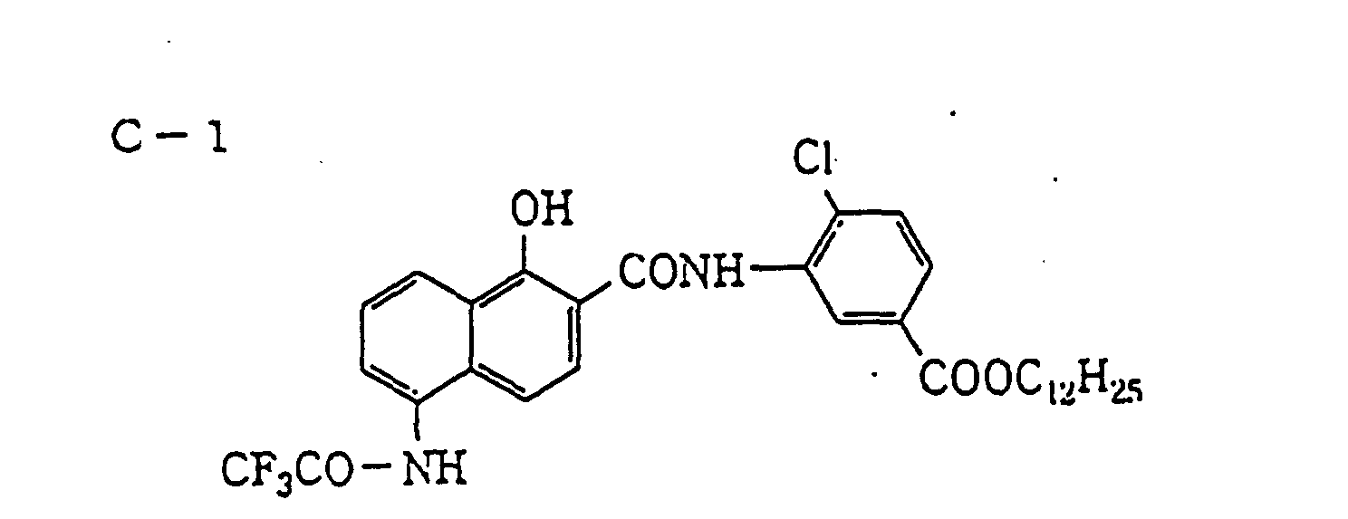


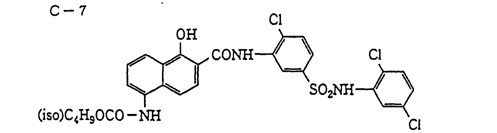
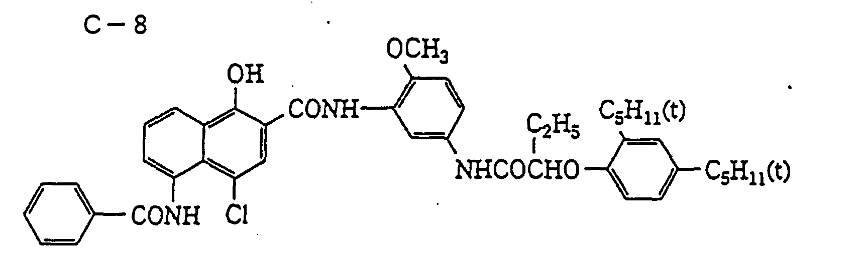
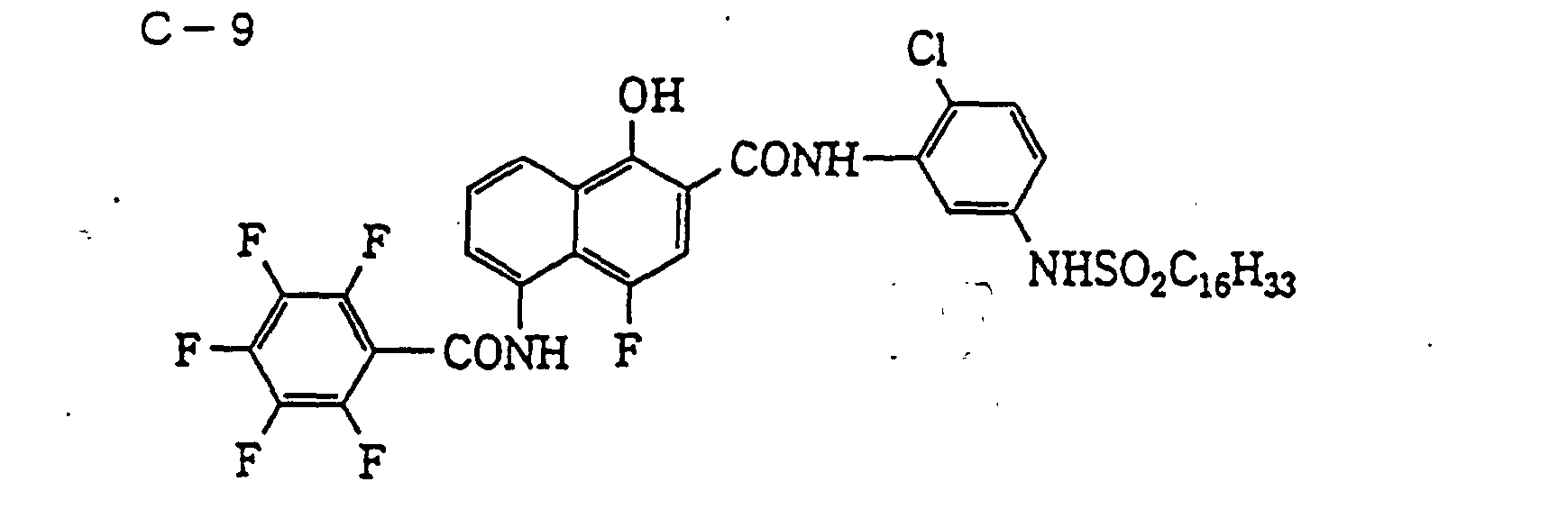


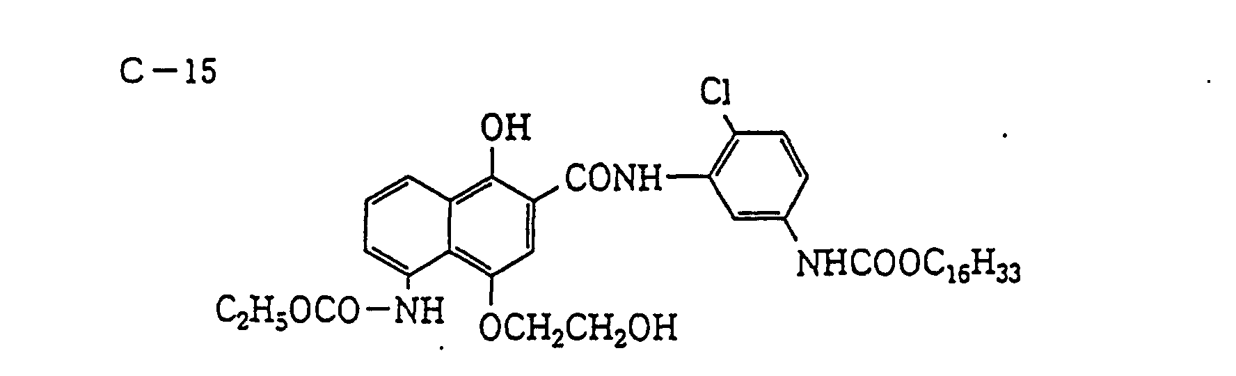


- The amount of the infrared dye-forming coupler for use in the present invention is not particularly limited, however, it is preferably from 0.01 to 1.00 g/m2.
- The infrared dye-forming coupler may be added to any layer of the light-sensitive material, however, the color sensitivity of silver halide needs be adjusted so that the infrared dye is contained at least in a red image picture area formed when the light-sensitive material is developed, because out of red, green and blue, red transmits near infrared light most. Therefore, the infrared dye-forming coupler is added to the same layer as the magenta coupler and/or the yellow coupler or to the same layer as the silver halide emulsion layer having the same color sensitivity as these couplers. Alternatively, the infrared dye-forming coupler may be used together with a silver halide emulsion having color sensitivity different from yellow, magenta and cyan respective couplers and subjected to superposition exposure at the time of exposure of the light-sensitive material to thereby form an infrared dye in the red image picture area. The infrared dye may be formed, if desired, in the green, blue, black or other image picture area.
- The above-described silver halide color light-sensitive material (the first silver halide color light-sensitive material) is subjected to pattern exposure by fluorescent tube, CRT, plasma, light emitting diode (LED) or laser as a light source according to digital signals programmed so that red, green and blue colors can be formed, the black matrix area can be substantially colorless and a pixel pattern in the shape required can be obtained. In this case, a laser ray is preferred because the light spot size can be reduced and a high-precision pattern can be written at high speed.
- With respect to the term "the black matrix area is substantially colorless", it is enough if the quantity of light necessary for forming sufficiently black color in the black matrix area can be obtained when the silver halide light-sensitive material (b) for color filter is exposed to white light through the master color filter (a) manufactured, and the area may be colored to gray or other color for controlling the quantity of light (excessive quantity of light causes blur and the pattern obtained becomes poor in the edge sharpness).
- In the present invention, the exposure pattern, namely, the pixel pattern of the master color filter (a) can be easily varied by performing digital exposure using at least three laser light sources. The laser may be selected from various gas lasers, liquid lasers, solid lasers, semiconductor lasers and semiconductor diodes, according to the color sensitivity of the light-sensitive material used. Further, the exposure may also be performed using a wavelength conversion element obtained by combining a nonlinear optical material and a coherent light source such as laser ray. The term "nonlinear optical element" as used herein means a material capable of giving nonlinearity between the polarization and the electric field appeared upon application of a strong photoelectric field such as laser rays. Preferred examples of this material include an inorganic compound such as lithium niobate, potassium dihydrogenphosphate (KDP), lithium iodate and BaB2O4, a urea derivative, a nitroaniline derivative, a nitropyridine-N-oxide derivative such as 3-methyl-4-nitropyridine-N-oxide (POM), and the compounds described in JP-A-61-53462 and JP-A-62-210432. The wavelength conversion element is known to have the monocrystal optical waveguide path form or the fiber form and either is useful.
- The exposure method and exposure apparatus which can be used in the present invention are described in JP-A-2-129625, JP-A-5-176144, JP-A-5-199372, JP-A-6-127021, JP-A-7-15593, JP-A-7-140567, JP-A-7-248549, JP-A-7-248541, JP-A-7-295115, JP-A-7-290760, JP-A-7-301868, JP-A-7-301869, JP-A-7-306481 and JP-A-8-15788. Various commercially available laser exposure apparatuses can of course be used.
- The silver halide color light-sensitive material after the above-described pattern exposure is processed according to the known normal development processing and thereby, a master color filter (a) colored to red, green and blue and having a substantially colorless black matrix area is obtained.
- The silver halide color light-sensitive material (b) for (the second silver halide color light-sensitive material) color filter for use in the present invention is a silver halide color light-sensitive material comprising a transparent substrate having thereon at least a red-sensitive silver halide emulsion layer containing a coupler having sensitivity to the red of the master color filter (a) and forming a red color, a green-sensitive silver halide emulsion layer containing a coupler having sensitivity to the green of the master color filter (a) and forming a green color, a blue-sensitive silver halide emulsion layer containing a coupler having sensitivity to the blue of the master color filter (a) and forming a blue color, and an infrared-sensitive emulsion. The coupler which forms a red color may be a combination of a yellow coupler with a magenta coupler or a red coupler capable of solely forming a red color. The coupler which forms a green color may be a combination of a yellow coupler with a cyan coupler or a green coupler capable of solely forming a green color. The coupler which forms a blue color may be a combination of a cyan coupler with a magenta coupler or a coupler capable of solely forming a blue color.
- According to one embodiment of the silver halide light-sensitive material (b) for color filter used in the present invention, a material having a characteristic curve shown in Fig. 1 is used, the blue-sensitive emulsion layer contains a cyan coupler and a magenta coupler (or contains a blue coupler), the green-sensitive emulsion layer contains a yellow coupler and a cyan coupler (or contains a green coupler), and the red-sensitive emulsion layer contains a yellow coupler and a magenta coupler (or contains a red coupler). In Fig. 1, symbol "a" corresponds to a red-sensitive emulsion, symbol "b" corresponds to a green-sensitive emulsion, symbol "c" corresponds to a blue-sensitive emulsion and symbol "d" corresponds to an infrared-sensitive emulsion. This silver halide light-sensitive material for color filter is exposed to blue, green, red and white lights using a master color filter as shown in Fig. 2 having a pattern in a density capable of giving exposure at the positions of point A and point B in Fig. 1. In Fig. 2, the background area is substantially colorless and transparent, but may be colored to gray or other color for controlling the quantity of light. Thereafter, the light-sensitive material is subjected to color development, desilvering (bleach-fixing) and water washing and then a color filter having formed thereon blue, green and red colors as shown in Fig. 3 is obtained. In Fig. 3, the background area is black.
- Fig. 4 shows another embodiment of the layer structure of the silver halide light-sensitive material (b) for color filter used in the present invention. In Fig. 4,
reference numeral 1 represents a protective layer,reference numeral 2 represents an antihalation layer, andreference numeral 3 represents a support. As shown in Fig. 4, a coupler in the same system can be added to a layer adjacent to each silver halide emulsion layer, therefore, color mixing of dyes between respective emulsion layers can be restrained even without the interposition of an interlayer and the color filter can be reduced in the thickness. Of course, an interlayer can be disposed between emulsion layers having different color sensitivities and in this case, the amount of the color mixing inhibitor added can be reduced. In manufacturing a color filter using this silver halide light-sensitive material, the silver halide light-sensitive material is, in the same manner as above, exposed using a master color filter as shown in Fig. 2 and then subjected to color development, bleach-fixing and water washing. In this silver halide light-sensitive material, the silver halide emulsion layers different in the color sensitivity each is constituted by at least two unit layers. The unit layers having the same color sensitivity may be different or the same in the sensitivity. These two unit layers each contains at least one coupler such that the hues formed are different between layers. - In the above-described silver halide light-sensitive material, the order of providing three silver halide emulsion layers having color sensitivity to red, green or blue is not limited to the order above but may be freely selected. In addition to the above-described layer structure, a subbing layer, an interlayer, a yellow filter layer capable of bleaching, a protective layer or an ultraviolet absorbing layer may be provided, if desired.
- In the present invention, when one-shot exposure with white light is performed, in the case of equal magnification, the master color filter (a) is placed close to or in contact with the silver halide light-sensitive material (b) for color filter and the binder layers of these two light-sensitive materials face each other. The master color filter (a) may be improved in the adhesion or blur when it is exposed in the state such that the surface on the support side is laminated with a rigid transparent material such as glass or a load such as glass is imposed thereon.
- In the present invention, the pixel pattern of the master color filter (a) may be enlarged or reduced to a similitude by means of a camera for the photomechanical process and exposed on a silver halide light-sensitive material (b) for color filter. In particular, when a pixel pattern of the master color filter (a) is formed larger than the desired size and reduced upon printing, the color filter obtained has a pattern of higher precision and the digital exposure by laser or the like is advantageously facilitated.
- Further, in order to concord the quantity of red, green, blue or white light transmitted through the master color filter (a) with the sensitivity characteristics in the spectrum of the silver halide light-sensitive material (b) for color filter, a color correction filter of various types or an ND (Neutral Density) filter may be interposed between the white light source and the master color filter (a) on exposure.
- The silver halide grain which can be used in the silver halide light-sensitive material (b) for color filter of the present invention includes silver chloride, silver bromide, silver iodochloride, silver chlorobromide and silver iodochlorobromide. The silver chloride content is preferably 50 mol% or more, more preferably 80 mol% or more. The silver iodide content is preferably 2 mol% or less, more preferably 1 mol% or less, still more preferably 0.5 mol% or less.
- The silver halide emulsion for use in the present invention may be a homogeneous crystal structure grain or a multiple structure grain having different halogen compositions between the inside of the grain and the surface of the grain. Further, silver halide having a different composition may be joined to the grain by epitaxial conjunction. Furthermore, a compound other than silver halide, such as silver rhodanate or lead oxide, may be joined thereto.
- In particular, the high silver chloride emulsion for use in the present invention may have a structure such that a stratified or non-stratified silver bromide localized phase is present in the inside and/or surface of silver halide. The halogen composition in the localized phase preferably has a silver bromide content of at least 20 mol%, more preferably in excess of 30 mol%. The silver bromide content in the silver bromide localized phase can be analyzed by the X-ray diffraction method. The application method of the X-ray diffraction method to silver halide grains is described in, for example, C.R. Berry and S.J. Marino, Photographic Science and Technology, Vol. 2, p. 149 (1955), and ibid., Vol. 4, p. 22 (1957). The silver bromide localized phase may be present in the inside of a grain, or at the edge or corner of or on the plane of the grain surface, however, it is preferably joined to the corner part of a grain by epitaxial conjunction.
- In order to achieve a large specific surface area and a high development activity while reducing the silver amount as much as possible, the average grain size of silver halide grains for use in the present invention is preferably from 0.05 to 0.9 µm, more preferably from 0.1 to 0.5 µm. In the case of a tabular grain, the thickness is preferably from 0.05 to 0.9 µm, more preferably from 0.1 to 0.5 µm.
- A monodisperse emulsion having a narrow grain size distribution may also be used. The monodisperse emulsion is a silver halide emulsion, for example, having a grain size distribution such that 80% or more by number or weight of all grains have a size falling within the average grain size ± 30%. Also, a monodisperse silver halide emulsion having a coefficient of variation of 20% or less, preferably 15% or less, may be used.
- A polydisperse emulsion having a wide grain size distribution may also be used.
- The silver halide emulsion which can be used in the present invention may be prepared by the method described, for example, in Research disclosure (RD) "I. Emulsion Preparation and Types", Vol. 176, No. 17643, pp. 22-23 (December, 1978), ibid., No. 18716, p. 648 (November, 1979), P. Glafkides, Chimie et Physique Photographique, Paul Montel (1967), G.F. Duffin, Photographic Emulsion Chemistry, the Focal Press (1966), and V.L. Zelikman et al, Making and Coating Photographic Emulsion, the Focal Press (1964).
- The monodisperse emulsions described in U.S. Patents 3,574,628 and 3,655,394 and British Patent 1,413,748 are also preferred.
- Furthermore, a tabular grain having an aspect ratio of about 5 or more may also be used in the present invention. The tabular grain may be easily prepared by the methods described in Gutoff, Photographic Science and Engineering, Vol. 14, pp. 248-257 (1970), U.S. Patents 4,434,226, 4,414,310, 4,433,048 and 4,439,520, and British Patent 2,112,157.
- A mixture of grains having various crystal forms may also be used.
- The light-sensitive silver halide emulsion is usually a silver halide emulsion subjected to chemical sensitization. The chemical sensitization of the light-sensitive silver halide emulsion for use in the present invention may be performed by chalcogen sensitization such as sulfur sensitization, selenium sensitization and tellurium sensitization, noble metal sensitization using gold, platinum or palladium, or reduction sensitization, which are known to the emulsion for normal light-sensitive materials, and these sensitization methods may be used individually or in combination (see, for example, JP-A-3-110555 and Japanese Patent Application No. 4-75794). The chemical sensitization may also be performed in the presence of a nitrogen-containing heterocyclic compound (see, JP-A-62-253159). Further, an antifoggant which will be described later may be added after completion of the chemical sensitization. More specifically, the methods described in JP-A-5-45833 and JP-A-62-40446 may be used.
- At the time of chemical sensitization, the pH is preferably from 5.3 to 10.5, more preferably from 5.5 to 8.5, and the pAg is preferably from 6.0 to 10.5, more preferably from 6.8 to 9.0.
- The coating amount of the light-sensitive silver halide emulsion for use in the present invention is from 1 mg/m2 to 10 g/m2 as calculated in terms of silver.
- The light-sensitive silver halide emulsion for use in the present invention is subjected to spectral sensitization with a methine dye or the like so that the light-sensitive silver halide can have color sensitivity to green, red or infrared. Further, the blue-sensitive emulsion may be subjected to spectral sensitization in the blue region, if desired.
- The dye which can be used includes cyanine dyes, merocyanine dyes, complex cyanine dyes, complex merocyanine dyes, holopolar cyanine dyes, hemicyanine dyes, styryl dyes and hemioxonol dyes.
- Specific examples thereof include sensitizing dyes described in U.S. Patent 4,617,257, JP-A-59-180550, JP-A-64-13546, JP-A-5-45828 and JP-A-5-45834.
- These sensitizing dyes may be used individually or in combination thereof, and the combination of sensitizing dyes is often used for the purpose of supersensitization or for controlling the wavelength of spectral sensitivity.
- Together with the sensitizing dye, a dye which itself has no spectral sensitization effect, or a compound which absorbs substantially no visible light, but which exhibits supersensitization may be incorporated into the emulsion (for example, those described in U.S. Patent 3,615,641 and JP-A-63-23145).
- The sensitizing dye may be added to the emulsion before, during or after chemical ripening, or may be added before or after nucleation of silver halide grains according to U.S. Patents 4,183,756 and 4,225,666. The sensitizing dye or supersensitizer may be added as a solution of an organic solvent such as methanol, a dispersion of gelatin or a solution of a surface active agent. The amount added is in general on the order of from 10-8 to 10-2 mol per mol of silver halide.
- The additives for use in these steps are described in RD, No. 17643, ibid., No. 18716 and ibid., No. 307105, and the pertinent parts thereof are summarized below.
Kinds of Additives RD17643 RD18716 RD307105 1. Chemical sensitizer p. 23 p. 648, right col. p. 866 2. Sensitivity increasing agent p. 648, right col. 3. Spectral sensitizer, supersensitizer pp. 23-24 p. 648, right col.-p. 649, right col. pp. 866-868 4. Brightening agent p. 24 p. 648, right col. p. 868 5. Antifoggant, stabilizer pp. 24-25 p. 649, right col. pp. 868-870 6. Light absorbent, filter dye, UV absorbent pp. 25-26 p. 649, right col.-p. 650, left col. p. 873 7. Dye image stabilizer p. 25 p. 650, left col. p. 872 8. Hardening agent p. 26 p. 651, left col. pp. 874-875 9. Binder p. 26 p. 651, left col. p. 873-874 10. Plasticizer, lubricant p. 27 p. 650, right col. p. 876 11. Coating aid, surface active agent pp. 26-27 p. 650, right col. pp. 875-876 12. Antistatic agent p. 27 p. 650, right col. pp. 876-877 - The color developing agent which can be used in the present invention may be sufficient if the oxidation product of the developing agent formed on the development of silver halide makes coupling reaction with a coupler to form a dye and such a color developing agent is known in the photographic field. Specific examples of the color developing agent are described in T.H. James, The Theory of the Photographic Process, 4th ed., pp. 291-334 and pp. 353-361. A particularly preferred color developing agent is a p-phenylenediamine derivative. The color developing agents described in JP-A-8-254610 and JP-A-7-333107 can also be used.
- In the present invention, various known color couplers may be used, and specific examples thereof are described in patents cited in Research Disclosure (RD), No. 17643, VII-C to G.
- As the coupler for use in the present invention, a two-equivalent coupler substituted by a splitting-off group is preferred more than a four-equivalent color coupler having a hydrogen atom at the active site because the coated silver amount can be reduced.
- A representative example of the yellow coupler which can be used in the present invention is an oil protect-type acylacetamide-base coupler. Specific examples thereof are described in U.S. Patents 2,407,210, 2,875,057 and 3,265,506. In the present invention, a two-equivalent yellow coupler is preferably used and representative examples thereof include oxygen atom-releasing yellow couplers described in U.S. Patents 3,408,194, 3,447,928, 3,935,501 and 4,022,620, and nitrogen atom-releasing yellow couplers described in JP-B-58-10739, U.S. Patents 4,401,752 and 4,326,024, RD, 18053 (April, 1979), British Patent 1,425,020, West German Patent Publication (OLS) Nos. 2,219,917, 2,261,361, 2,329,587 and 2,433,812. The α-pivaloylacetanilide-base coupler is excellent in the fastness, particularly light fastness, of the colored dye, whereas the α-benzoylacetanilide-base coupler can provide a high color density.
- The magenta coupler which can be used in the present invention includes oil protect-type, preferably, 5-pyrazolone-base couplers and pyrazoloazole-base couplers such as pyrazolotriazoles. The 5-pyrazolone-base coupler is preferably substituted by an arylamino group or an acylamino group at the 3-position in view of hue and color density of the colored dye. Representative examples thereof are described in U.S. Patents 2,311,082, 2,343,703, 2,600,788, 2,908,573, 3,062,653, 3,152,896 and 3,936,015. The splitting-off group of the two-equivalent 5-pyrazolone-base coupler is particularly'preferably the nitrogen atom splitting-off group described in U.S. Patent 4,310,619 or the arylthio group described in U.S. Patent 4,351,897. The 5-pyrazolone-base coupler having a ballast group described in European Patent 73,636 can provide a high color density.
- The pyrazoloazole-base coupler includes pyrazolobenzimidazoles described in U.S. Patent 3,369,879, preferably pyrazolo[5,1-c][1,2,4]triazoles described in U.S. Patent 3,725,067, pyrazolotetrazoles described in Research Disclosure, No. 24220 (June, 1984), and pyrazolopyrazoles described in Research Disclosure, No. 24230 (June, 1984). In view of small yellow side absorption and light fastness of the colored dye, imidazo[1,2-b]pyrazoles described in European Patent 119,741 are preferred, and pyrazolo[1,5-b][1,2,4]triazole described in European Patent 119,860 is particularly preferred.
- The cyan coupler which can be used in the present invention includes naphthol-base couplers described in U.S. Patents 2,474,293, 4,052,212, 4,146,396, 4,228,233 and 4,296,200, phenolic cyan couplers having an alkyl group of ethyl or greater group at the meta-position of the phenol nucleus described in U.S. Patent 3,772,002, 2,5-diacylamino-substituted phenolic couplers described in U.S. Patents 2,772,162, 3,758,308, 4,126,396, 4,334,011 and 4,327,173, West German Patent Publication (OLS) No. 3,329,729 and JP-B-3-18175, and phenolic couplers having a phenylureido group at the 2-position and an acylamino group at the 5-position described in U.S. Patents 3,446,622, 4,333,999, 4,451,559 and 4,427,767. In particular, carbostyryl-base couplers described in JP-A-7-294714 are preferably used in the present invention because the couplers have excellent heat resistance and light resistance. As the cyan coupler for green color, pyrolotriazole-base couplers described in JP-A-8-179122 and JP-A-8-136722 are useful.
- Other than the above-described couplers, various couplers described below can be used in the present invention.
- Typical examples of the dye forming polymer coupler are described in U.S. Patents 3,451,820, 4,080,211 and 4,367,282, and British Patent 2,102,173. Examples of the coupler which solely forms a red color includes the red polymer coupler obtained by copolymerizing a yellow coupler component and a magenta coupler component described in JP-A-9-189986. Examples of the coupler which solely forms a green color include the green polymer coupler obtained by copolymerizing a yellow coupler component with a cyan coupler component described in JP-A-9-204026. Examples of the coupler which solely form a blue color include the blue polymer coupler obtained by copolymerizing a cyan coupler component and a magenta coupler component described in JP-A-9-204027.
- A coupler which releases a photographically useful residue upon coupling is also preferably used in the present invention. Preferred examples of the DIR coupler which releases a development inhibitor are described in patents cited in RD, No. 17643, Item VII-F, JP-A-57-151944, JP-A-57-154234, JP-A-60-184248 and U.S. Patent 4,248,962.
- As the coupler which imagewise releases a nucleating agent or development accelerator upon development, those described in British Patents 2,097,140 and 2,131,188, JP-A-59-157638 and JP-A-59-170840 are preferred.
- In addition, couplers which can be used in the light-sensitive material for use in the present invention include competitive couplers described in U.S. Patent 4,130,427, polyequivalent couplers described in U.S. Patents 4,283,472, 4,338,393 and 4,310,618, DIR redox compound-releasing couplers described in JP-A-60-185950, and couplers which release a dye capable of recovering the color after being released described in European Unexamined Patent Publication 173,302A.
- In the present invention, the equivalent ratio of the coupler to silver halide in each silver halide emulsion layer is preferably from 1 to 3. In particular, when a silver halide emulsion used has an average grain size (in the case of a tabular grain, determined by the thickness) of 0.9 µm or less, particularly 0.5 µm or less, the equivalent ratio is preferably from 1 to 2. The term "equivalent ratio" as used herein has meaning such that assuming that the theoretical amount of silver halide necessary for all couplers to form a color is an equivalent ratio of 1, when silver halide is coated in an amount of, for example, two times the theoretical amount, the equivalent ratio is 2. In other words, when a 2-equivalent coupler is used and the coated silver amount is 2 mols based on 1 mol of the coupler, the equivalent ratio is 1, and when the coated silver amount is 4 mol, the equivalent ratio is 2.
- The coupler for use in the present invention may be incorporated into the light-sensitive material by various known dispersion methods.
- Examples of the high boiling point solvent for use in the oil-in-water dispersion method are described in U.S. Patent 2,322,027. The amount of the high boiling point solvent is 10 g or less, preferably 5 g or less, more preferably from 0.01 to 1 g, per g of the coupler, and 2 g or less, preferably 1 g or less, more preferably 0.5 g or less, per g of the binder. The size of the coupler dispersion (coupler emulsified product) obtained by the oil-in-water dispersion method is from 0.05 to 0.9 µm, preferably from 0.1 to 0.5 µm.
- The process and effect of the latex dispersion method and specific examples of the latex for impregnation are described in U.S. Patent 4,199,363 and West German Patent Publication (OLS) Nos. 2,541,274 and 2,541,230.
- In the light-sensitive material for use in the present invention, the coupler-containing layer preferably uses a dye image preservability improving compound described in European Unexamined Patent Publication EP0,277,589A2. In particular, it is preferably used in combination with a pyrazoloazole-base magenta coupler.
- More specifically, Compound (F) which reacts with the aromatic amine-base developing agent remaining after color development to produce a chemically inactive and substantially colorless compound and/or Compound (G) which reacts with an oxidation product of the aromatic amine-base developing agent remaining after color development to produce a chemically inactive and substantially colorless compound, are preferably used simultaneously or individually, for example, for preventing staining or other side reaction due to a colored dye produced by the reaction of the color developing agent or oxidation product thereof remaining in the layer with a coupler during storage after the processing.
- The silver halide emulsion layer or interlayer of the light-sensitive material for use in the present invention may contain a hydroquinone derivative, an aminophenol derivative, a gallic acid derivative or an ascorbic acid derivative as an antifoggant or a color mixing inhibitor. Among these compounds, preferred are those which hardly generate stains even upon heating at from 160 to 200°C.
- In order to prevent deterioration of the cyan dye image due to heat and, in particular, light, it is more effective to incorporate an ultraviolet absorbent into the cyan color forming layer and both layers adjacent thereto.
- Examples of the ultraviolet absorbent include benzotriazole compounds substituted by an aryl group (for example, those described in U.S. Patent 3,533,794), 4-thiazolidone compounds (for example, those described in U.S. Patents 3,314,794 and 3,352,681), benzophenone compounds (for example, those described in JP-A-46-2784), cinnamic ester compounds (for example, those described in U.S. Patents 3,705,805 and 3,707,395), butadiene compounds (for example, those described in U.S. Patent 4,045,229) and benzoxazole compounds (for example, those described in U.S. Patents 3,406,070 and 4,271,307). An ultraviolet light absorbing coupler (e.g., α-naphthol-base cyan dye forming coupler) or an ultraviolet absorbing polymer may also be used. The ultraviolet absorbent may be mordanted to a specific layer. Among these ultraviolet absorbents, the benzotriazole compound substituted by an aryl group is preferred.
- To the light-sensitive material for use in the present invention, an antifungal or antiseptic as described in JP-A-63-271247 is preferably added so as to prevent various molds and bacteria from proliferation in the hydrophilic colloid layer to deteriorate the image.
- Gelatin is advantageous as the binder or protective colloid which can be used in the silver halide emulsion layer, the interlayer or the protective layer of the light-sensitive material for use in the present invention, however, other hydrophilic polymers may also be used. Examples of the hydrophilic polymer include polyvinyl alcohol, polyvinyl alcohol partial acetal, polyvinyl butyral, poly-N-vinylpyrrolidone, polyacrylic acid, polyacrylamide, polyvinylimidazole, polyvinylpyrazole, carrageenan, gum arabi and a homopolymer or copolymer of cellulose derivatives such as hydroxyalkyl cellulose, carboxymethyl cellulose, cellulose sulfate, cellulose acetate hydrogen phthalate and sodium alginate.
- Also, a graft polymer of gelatin with other polymer may be used and examples of the gelatin graft polymer include those obtained by grafting an acrylic acid, a methacrylic acid, a derivative such as ester or amide of the acrylic acid or methacrylic acid, or a homopolymer or copolymer of vinyl-base monomers such as acrylonitrile or styrene, to gelatin. In particular, graft polymers to a polymer having somewhat compatibility with gelatin, such as a polymer of acrylic acid, methacrylic acid, acrylamide, methacrylamide or hydroxyalkyl methacrylate, are preferred. Examples thereof are described in U.S. Patents 2,763,625, 2,831,767 and 2,956,884, and JP-A-56-65133.
- Representative examples of the synthetic hydrophilic polymer material which can be used are described in West German Patent Publication (OLS) No. 2,312,708, U.S. Patents 3,620,751 and 3,879,205, and JP-B-43-7561.
- The above-described hydrophilic polymers may be used either individually or in combination of two or more thereof.
- The gelatin may be an alkali-processed gelatin, an acid-processed gelatin, an enzyme-processed gelatin or a mixture of these. Further, a gelatin derivative obtained by reacting various compounds such as an acid halide, an acid anhydride, an isocyanate, a bromoacetic acid, an alkanesultone acid, a vinylsulfonamide, a maleinimide compound, a polyalkylene oxide or an epoxy compound, with gelatin may also be used. Specific examples of the gelatin derivative are described in U.S. Patents 2,614,928, 3,132,945, 3,186,846 and 3,312,553, British Patents 861,414, 1,033,189 and 1,005,784, and JP-B-42-26845.
- The total binder amount in the light-sensitive material for use in the present invention is preferably from 3 to 10 g/m2, and the amount of binder contained in each silver halide emulsion layer or interlayer is preferably from 0.1 to 1.5 g/m2, more preferably from 0.2 to 1.0 g/m2.
- The support for use in the present invention is preferably a light-transmitting substrate, however, as described in JP-A-7-244212, silver halide emulsion layers provided on a separate support may be transferred and firmly bonded onto a light-transmitting substrate to prepare a light-sensitive material for color filter. In this case, the support is not necessarily required to be light-transmitting and for example, a support having coated on the back surface thereof carbon black or the like may be used.
- In this case, the binder in the release layer or back layer provided is not counted in the above-described "total binder amount".
- The material constituting the light-transmitting substrate preferably has an optically isotropic property and excellent heat resistance and examples thereof include polyethylene terephthalate, polybutylene terephthalate, polyethylene naphthalate, polystyrene, polycarbonate, polyether sulfone, cellulose acetate, polyarylate, soda glass, borosilicate glass and quartz.
- The surface of the substrate constituted by the above-described material may be subjected to undercoating treatment, if desired. Further, the surface may be subjected to glow discharge, corona discharge or ultraviolet (UV) irradiation treatment.
- The light-transmitting substrate may be used in the form of a plate, a sheet or a film. The thickness of the substrate may be appropriately selected depending upon the use and the construction material, however, it is commonly from 0.01 to 10 mm. For example, in the case of a glass substrate, the thickness is from 0.3 to 3 mm.
- The light-sensitive material for use in the present invention is subjected to color development by the usual methods described in RD, No. 17643, pp. 28-29 and ibid., No. 18716, p. 651, left to tight columns, to obtain a microcolor filter.
- For example, the light-sensitive material is subjected to color development, desilvering and water washing. In the desilvering process, bleach-fixing processing using a bleach-fixing solution may be performed in place of bleaching using a bleaching solution and fixing using a fixing solution, or bleaching, fixing and bleach-fixing may be combined in any order. Stabilization may be performed in place of water washing, or stabilization may be performed after water washing. Further, mono-bath processing using a mono-bath developing-bleaching-fixing processing solution capable of conducting color development, bleaching and fixing in one bath may also be performed. In combination with these processing steps, pre-hardening processing, neutralization processing therefor, stop-fixing processing, after-hardening processing, regulating or intensification may be performed. In the above-described processing, so-called activator processing may be performed in place of color development processing.
- With respect to the developing apparatus, in the case of a flexible support (substrate), a developing machine used in usual photographic processing may be used. In the case of a hard support such as glass, a developing machine for glass dry plate or a developing apparatus described in JP-A-7-56015 may be used.
- On the color filter produced by the process of the present invention, a heat-resistant and water-proof resin having a high electric resistivity may be provided as an outermost protective layer (overcoat layer). Examples of the resin are described in U.S. Patents 4,171,979, 4,049,861, 4,333,998, 4,698,295 and 4,668,601, European Unexamined Patent Publications 179636A and 556810A, JP-A-3-163416, JP-A-3-188153, JP-A-5-78443, JP-A-1-276101, JP-A-2-179628, JP-A-5-19115, JP-A-5-173012, JP-A-5-264811, JP-A-60-216307, JP-A-63-218771, JP-A-52-22099, JP-A-52-22100, JP-A-53-142447, JP-A-54-137072, JP-A-54-83999, JP-A-55-125104, JP-A-53-57023, JP-A-53-121100, JP-A-56-91233, JP-A-57-90489, JP-A-62-21150, JP-A-62-23042, JP-A-62-23043, JP-A-62-24256, JP-A-62-25758, JP-A-62-229133 and Japanese Patent Application Nos. 8-235621, 8-238154 and 8-276027.
- On the color filter produced by the process of the present invention, a transparent electrode (ITO) may be provided by evaporation coating, for example, vacuum evaporation or sputtering.
- Further thereon, an orientating layer of polyimide resin or the like may be provided.
- Furthermore, a deflecting plate or plate difference film may be provided on the surface opposite to the emulsion surface side of the light-transmitting substrate of the color filter.
- In place of the glass plate, a plastic film substrate having provided thereon a gas barrier layer or hard coat layer may be used as the light-transmitting substrate.
- The color LCD and the production method thereof are described in detail in Shoichi Matsumoto and Ichiryo Tsunoda, Ekisho no Kiso to Oyo (Basic Study and Application of Liquid Crystal), issued by Kogyo Chosa Kai (1991), Flat Panel Display, 1996, complied by Nikkei Microdevice, issued by Nikkei BP Sha (1995), Oyo Butsuri (Applied Physics), Vol. 64, No. 10, p. 1042 (1995) and JP-A-1-114820.
- The present invention will be described in greater detail with reference to the following Examples.
- Examples 1 and 2 are not in accordance with the present invention.
- A color positive film for movies "Fuji Color Positive Film CL" (produced by Fuji Photo Film Co., Ltd.) was subjected to digital exposure as shown in Fig. 2 from the emulsion surface thereof using an He-Cd laser (B light), a green semiconductor excited laser (using SHG) (G light) and an He-Ne laser (R light). Each RGB pixel had a size of 200 µm × 300 µm, the black matrix (BM) area had a width of 25 µm, and the entire picture plane size was 24 cm × 16 cm.
- The exposed light-sensitive material was developed according to the formulation of ECP-2B processing issued by Eastman Kodak Company to manufacture a master color filter having formed thereon RGB colors.
- A process for manufacturing a color filter using the master color filter prepared is described below.
- On a 100 µm-thick polyethylene terephthalate support having a back layer formed by coating carbon black dispersed in polyvinyl chloride, gelatin subbing was applied and thereon from the first to eighth layers each having the following structure were simultaneously coated one on another to prepare Color Light-Sensitive Material 1A. The components and the coated amounts (unit: g/m2) are shown below. With respect to the silver halide, the coated amount is calculated in terms of silver.
First Layer (release layer): Hydroxyethyl cellulose (HEC-5P500; produced by Daicel Chemical KK) 0.35 Terminal alkyl-modified polyvinyl alcohol (average polymerization degree: 300) 0.08 Antistatic Agent (Cpd-1) 0.03 Second Layer (gelatin adjacent layer): Gelatin 0.60 Third Layer (blue-sensitive layer): Silver halide emulsion spectrally sensitized by Blue Sensitizing Dyes (ExS-1 and ExS-2) (AgBr30Cl70; average grain size: 0.35 µm) 0.33 Gelatin 1.00 Cyan Coupler (ExC-2) 0.57 Magenta Coupler (ExM-3) 0.05 Ultraviolet Absorbent (Cpd-6) 0.03 Ultraviolet Absorbent (Cpd-7) 0.08 High Boiling Point Solvent (Solv-1) 0.23 Fourth Layer (interlayer): Gelatin 0.38 Color Mixing Inhibitor (Cpd-2) 0.02 Color Mixing Inhibitor (Cpd-10) 0.09 High Boiling Point Solvent (Solv-1) 0.03 High Boiling Point Solvent (Solv-3) 0.01 Ultraviolet Absorbent (Cpd-8) 0.02 Ultraviolet Absorbent (Cpd-7) 0.02 Ultraviolet Absorbent (Cpd-6) 0.01 Ultraviolet Absorbent (Cpd-9) 0.02 Polymer (Cpd-11) 0.04 Yellow Dye (YF-1) 0.17 Fifth Layer (green-sensitive layer): Silver halide emulsion spectrally sensitized by Green Sensitizing Dye (ExS-3) (AgCl; average grain size: 0.18 µm) 0.71 Gelatin 1.39 Cyan Coupler (ExC-1) 0.34 Yellow Coupler (ExY-2) 0.47 Discoloration Inhibitor (Cpd-5) 0.01 Stain Inhibitor (Cpd-13) 0.01 High Boiling Point Solvent (Solv-1) 0.27 High Boiling Point Solvent (Solv-2) 0.39 Polymer (Cpd-14) 0.03 Sixth Layer (interlayer): Gelatin 0.38 Color Mixing Inhibitor (Cpd-2) 0.02 Color Mixing Inhibitor (Cpd-10) 0.09 High Boiling Point Solvent (Solv-1) 0.03 High Boiling Point Solvent (Solv-3) 0.01 Ultraviolet Absorbent (Cpd-8) 0.02 Ultraviolet Absorbent (Cpd-7) 0.02 Ultraviolet Absorbent (Cpd-6) 0.01 Ultraviolet Absorbent (Cpd-9) 0.02 Polymer (Cpd-11) 0.04 Irradiation Preventive Dye (Dye-1) 0.005 Irradiation Preventive Dye (Dye-2) 0.02 Seventh Layer (red-sensitive layer): Silver halide emulsion spectrally sensitized by Red Sensitizing Dyes (ExS-4 and ExS-5) (AgCl; average grain size: 0.18 µm) 0.36 Gelatin 1.33 Yellow Coupler (EXY-1) 0.61 Magenta Coupler (ExM-2) 0.25 Discoloration Inhibitor (Cpd-3) 0.11 Discoloration Inhibitor (Cpd-4) 0.005 Discoloration Inhibitor (Cpd-5) 0.01 High Boiling Point Solvent (Solv-1) 0.43 High Boiling Point Solvent (Solv-2) 0.11 Polymer (Cpd-14) 0.03 Eighth Layer (protective layer): Gelatin 0.70 Antihalation dye (fine particle dispersion) 0.17 Carboxymethyl cellulose 0.05 Polymer (Cpd-15) 0.14 Surface Active Agent (Cpd-16) 0.03 Hardening Agent (H-1) 0.12 - In each layer, sodium dodecylbenzenesulfonate as an emulsification dispersion aid, ethyl acetate as an auxiliary solvent, Surface Active Agent (Cpd-17) as a coating aid and potassium polystyrenesulfonate as a thickening agent were used.


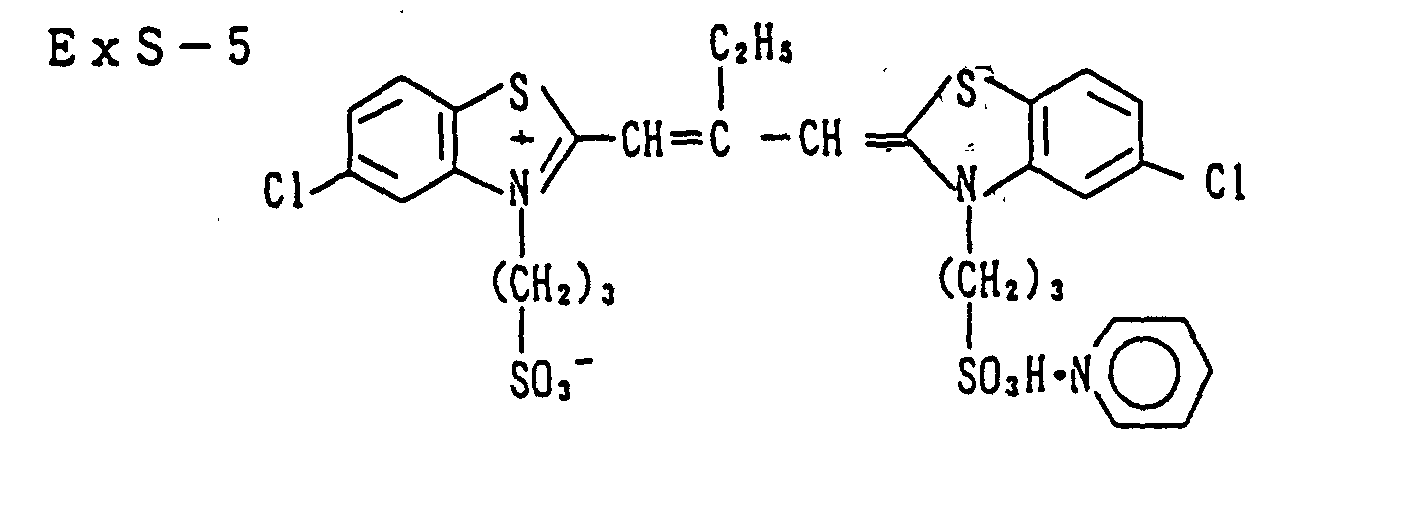


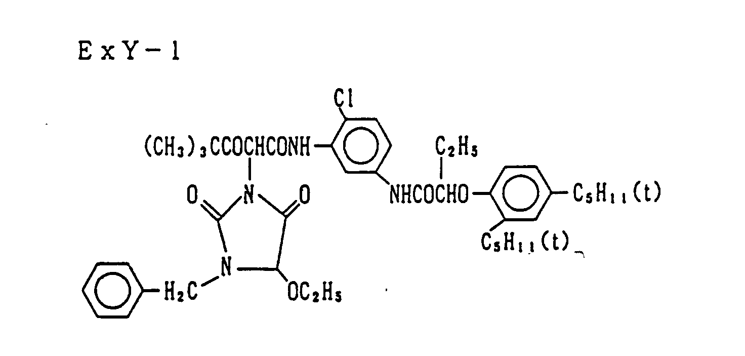

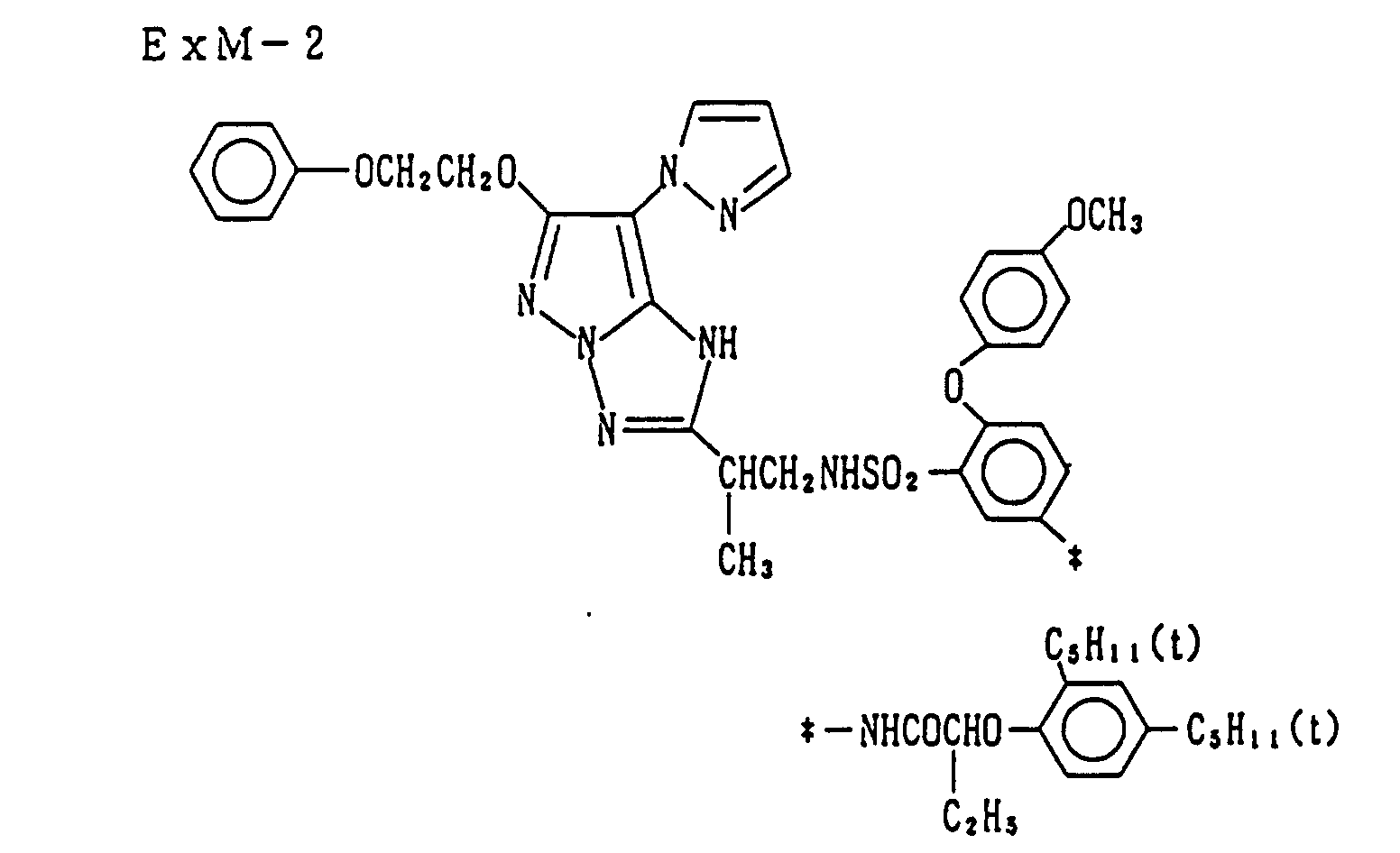

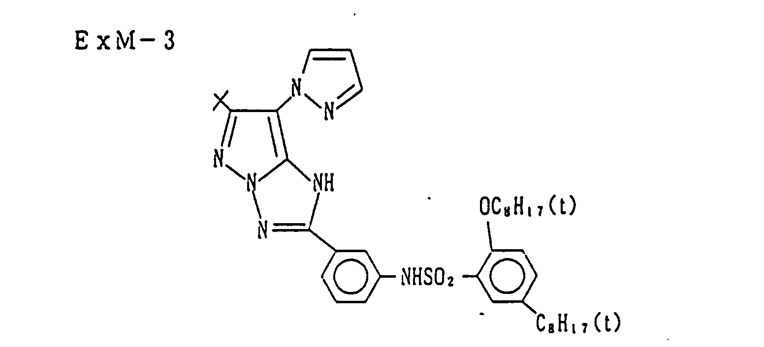

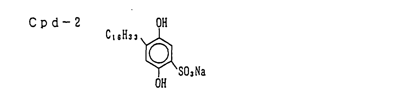


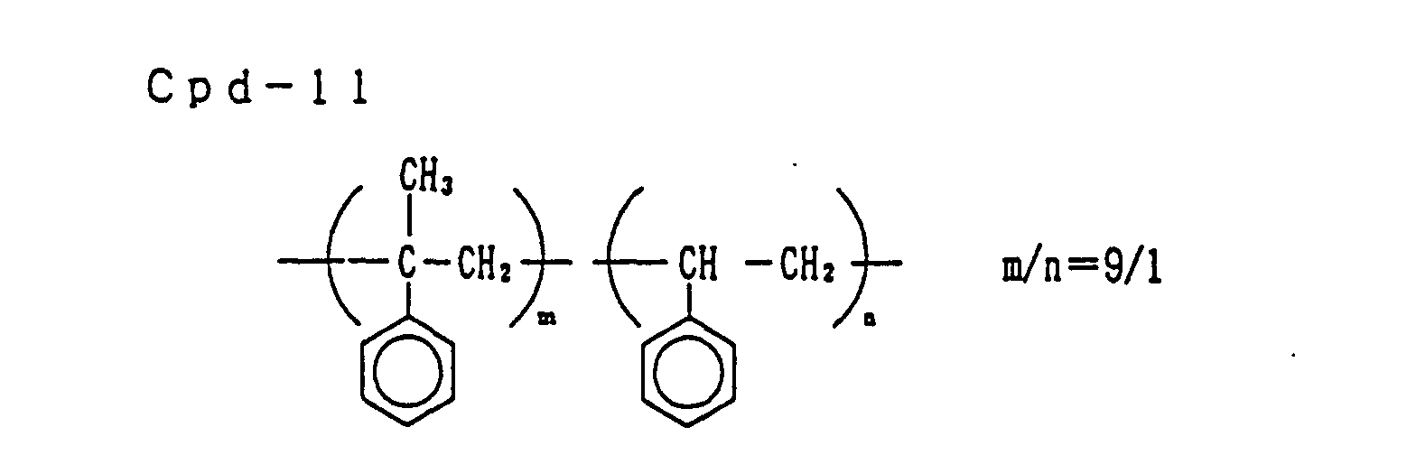
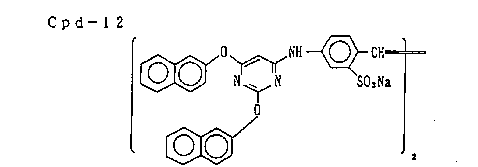


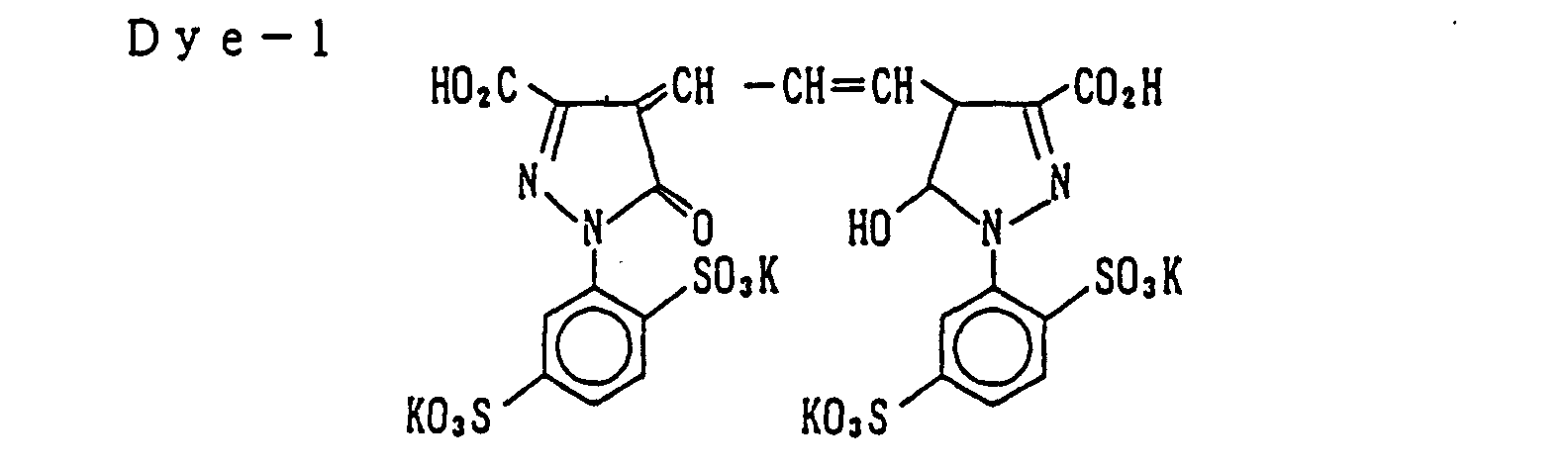
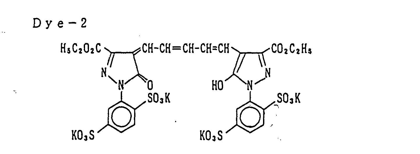


- A 0.7 mm-thick transparent alkali-free glass (20 cm × 30 cm) was used as the light-transmitting substrate. On the surface thereof, a 1:3 (by weight) mixture of gelatin and colloidal silica (average particle size: 7 to 9 mµ) having added thereto saponin as a surface active agent was coated. The dry thickness of the layer formed was 0.2 µm.
- The protective layer of Color Light-Sensitive Material 1A prepared above was adhered onto the coated surface of the light-transmitting substrate. The laminate obtained was traveled at a linear velocity of 0.45 m/min in a laminator where the temperature was set so that the temperature on the contact surface could be about 130°C. After the laminate was cooled almost to room temperature, the support of the light-sensitive material was peeled off together with the release layer from the emulsion surface. Then, second and upper emulsion layers were evenly bonded to the substrate and white spots were not observed.
- The thus-prepared substrate having emulsion layers was subjected to one-shot exposure from the emulsion surface side at an equal magnification or half (1/2) reduction through the master color filter prepared above using a camera for the photomechanical process. The exposed substrate was developed according to the following steps and as a result, a color filter having formed thereon BGR three colors and black color as shown in Fig. 3 in one operation was prepared.
Processing Step Temperature (°C) Time Hardening 38 3 min. Water washing-1 35 1 min. Color development 38 80 s Stopping 38 20 s Bleach-fixing 38 90 s Water washing-2 35 40 s Water washing-3 35 80 s Drying 60 2 min. - Each processing solution had the following composition. The stopping solution was an aqueous 2% acetic acid solution.
Hardening Solution: Sodium sulfate (anhydrous) 160.0 g Sodium carbonate (anhydrous) 4.6 g Glyoxal (40%) 50.0 ml Water to make 1 ℓ pH (25°C) 9.5 Color Developer: Water 800 ml D-Sorbitol 0.15 g Sodium naphthalenesulfonate·formalin condensate 0.15 g Pentasodium nitrilotris (methylenephosphonate) 1.8 g Diethylenetriaminepentaacetic acid 0.5 g 1-Hydroxyethylidene-1,1-diphosphonic acid 0.15 g Diethylene glycol 12.0 ml Benzyl alcohol 13.5 ml Potassium chloride 6.5 g Potassium bromide 0.1 g Potassium carbonate 30.0 g Sodium sulfite 2.4 g Disodium N,N-bis(sulfonatoethyl)- 8.0 g hydroxylamine Triethanolamine 6.0 g Benzotriazole 0.01 g N-Ethyl-N-(β-methanesulfonamidoethyl)-3-methyl-4- aminoaniline 3/2 sulfate monohydrate6.0 g Water to make 1 ℓ pH (25°C) 10.6 Bleach-Fixing Solution: Water 600 ml Ammonium thiosulfate (750 g/ℓ) 160 ml Ammonium sulfite 40.0 g Ammonium ethylenediaminetetraacetato ferrate 55.0 g Ethylenediaminetetraacetic acid 5.0 g Ammonium nitrate 10.0 g Ammonium bromide 25.0 g Water to make 1 ℓ pH (25°C) 6.0 - Deionized water having an electric conductivity of 5 µS or less
- On the color filter obtained, an overcoat agent "SS5333/SS0333" produced by Nippon Synthetic Rubber KK was coated by means of a spinner to have a dry thickness of 2.5 µm, pre-heated at 120°C for 30 minutes and then baked at 180°C for 30 minutes to form a protective layer.
- An optically isotropic 80 µm-thick polyarylate substrate having laminated on the back surface thereof a polypropylene protective layer (20 µm) was subjected to glow discharge treatment and thereon two layers of an SBR latex layer and a gelatin layer were coated so as to improve adhesion to the photographic emulsion layer. Further thereon, from the first to ninth layers each having the following structure were simultaneously coated one on another to prepare Color Light-Sensitive Material 2A. The components and the coated amounts (unit: g/m2) are shown below. With respect to the silver halide, the coated amount is calculated in terms of silver.
First Layer (antihalation layer): Gelatin 0.70 Antihalation dye (fine particle dispersion) 0.17 Carboxymethyl cellulose 0.05 Surface Active Agent (Cpd-16) 0.03 Hardening Agent (H-1) 0.05 Second Layer (first red-sensitive layer): Silver halide emulsion spectrally sensitized by Red Sensitizing Dyes (ExS-4 and ExS-5) (AgCl; average grain size: 0.18 µm) 0.11 Gelatin 0.70 Magenta Coupler (ExM-1) 0.15 Discoloration Inhibitor (Cpd-3) 0.08 Discoloration Inhibitor (Cpd-5) 0.01 High Boiling Point Solvent (Solv-4) 0.28 High Boiling Point Solvent (Solv-5) 0.14 Polymer (Cpd-11) 0.08 Third Layer (second red-sensitive layer): Silver halide emulsion spectrally sensitized by Red Sensitizing Dyes (ExS-4 and ExS-5) (AgCl; average grain size: 0.18 µm) 0.26 Gelatin 0.64 Yellow Coupler (ExY-1) 0.61 Stain Inhibitor (Cpd-13) 0.08 Discoloration Inhibitor (Cpd-5) 0.04 High Boiling Point Solvent (Solv-6) 0.24 Polymer (Cpd-14) 0.08 Fourth Layer (interlayer): Gelatin 0.38 Irradiation Preventive Dye (Dye-1) 0.005 Irradiation Preventive Dye (Dye-2) 0.02 Fifth Layer (first green-sensitive layer): Silver halide emulsion spectrally sensitized by Green Sensitizing Dye (ExS-3) (AgCl; average grain size: 0.18 µm) 0.23 Gelatin 0.62 Yellow Coupler (ExY-1) 0.54 Discoloration Inhibitor (Cpd-5) 0.03 Stain Inhibitor (Cpd-13) 0.07 High Boiling Point Solvent (Solv-6) 0.22 Polymer (Cpd-14) 0.07 Sixth Layer (second green-sensitive layer): Silver halide emulsion spectrally sensitized by Green Sensitizing Dye (ExS-3) (AgCl; average grain size: 0.18 µm) 0.19 Gelatin 0.68 Cyan Coupler (ExC-3) 0.20 Cyan Coupler (ExC-4) 0.03 High Boiling Point Solvent (Solv-7) 0.51 Polymer (Cpd-14) 0.02 Seventh Layer (interlayer): Gelatin 0.38 Color Mixing Inhibitor (Cpd-2) 0.02 Color Mixing Inhibitor (Cpd-10) 0.09 High Boiling Point Solvent (Solv-1) 0.03 High Boiling Point Solvent (Solv-3) 0.01 Ultraviolet Absorbent (Cpd-8) 0.02 Ultraviolet Absorbent (Cpd-7) 0.02 Ultraviolet Absorbent (Cpd-6) 0.01 Ultraviolet Absorbent (Cpd-9) 0.02 Polymer (Cpd-11) 0.04 Yellow Dye (YF-1) 0.17 Eighth Layer (blue-sensitive layer): Silver halide emulsion spectrally sensitized by Blue Sensitizing Dyes (ExS-1 and EXS-2) (AgBr30Cl70; average grain size: 0.35 µm) 0.33 Gelatin 0.98 Cyan Coupler (ExC-2) 0.57 Magenta Coupler (ExM-3) 0.05 Ultraviolet Absorbent (Cpd-6) 0.03 Ultraviolet Absorbent (Cpd-7) 0.08 High Boiling Point Solvent (Solv-1) 0.23 Hardening Agent (H-1) 0.08 Ninth Layer (protective layer): Gelatin (acid-processed) 0.65 Antistatic agent (Cpd-1) 0.01 Snowtex-O (produced by Nissan Kagaku Kogyo KK) 0.19 - In each layer, sodium dodecylbenzenesulfonate as an emulsification dispersion aid, ethyl acetate as an auxiliary solvent, Surface Active Agent (Cpd-17) as a coating aid and potassium polystyrenesulfonate as a thickening agent were used.

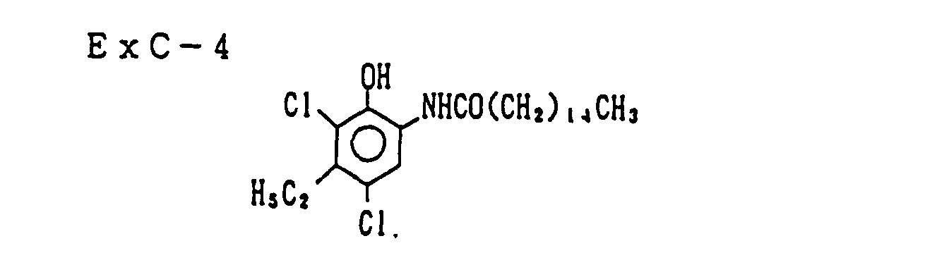



- Color Light-Sensitive Material 2A prepared above was subjected to contact exposure in one shot using the same master color filter as in Example 1 and then developed through the following steps. As a result, a color filter having formed thereon B, G, R three colors and black color in one operation was prepared. The processing solution were the same as those used in Example 1. The after-hardening solution was an aqueous 4% glutaraldehyde solution.
Processing Step Temperature (°C) Time Color development 38 80 s Bleach-fixing 38 90 s Water washing-1 35 40 s After-hardening 35 3 min. Water washing-2 35 2 min. Drying 60 2 min. - On the color filter layer obtained, the following composition was coated to have a dry thickness of 2.5 µm, then dried and hardened with ultraviolet rays to form a protective layer. The resulting color filter was good in the adhesion between the color filter layer and the protective layer and had good resistance against chemicals. Using the thus-manufactured color filter, a color liquid crystal panel comprising a plastic film substrate was produced.
Formulation of Overcoat Composition: Monomer (1) 77.4 wt% Monomer (2) 7.7 Polymer CAB 531 (produced by Eastman Chemical) 11.7 Photopolymerization initiator 2.4 Sensitizer 0.8 Diluting solvent (MEK) for coating - 
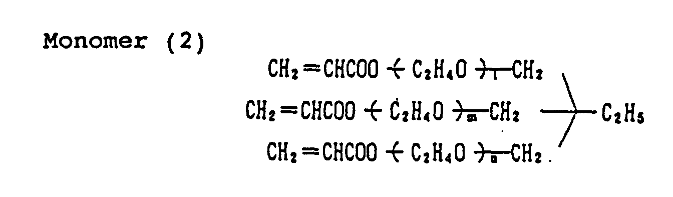
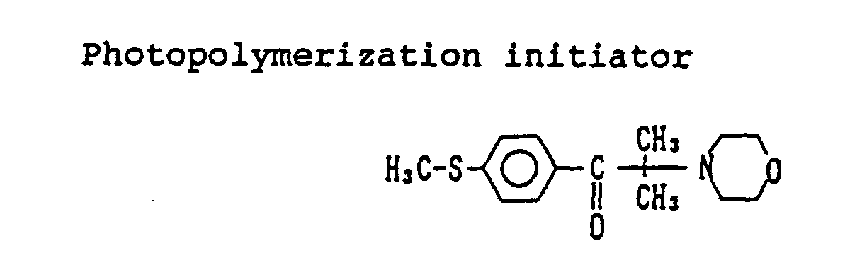
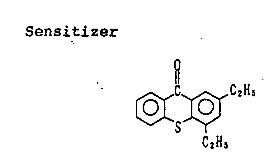
- A master color filter having any pixel pattern can be easily manufactured using a commercially available silver halide color light-sensitive material. By subjecting a silver halide color light-sensitive material for color filter to one-shot exposure using this master color filter and then to one-time development processing, a color filter can be easily manufactured within a short time. The color filter obtained has red, green and blue color areas excellent in the spectral characteristics.
- PEN-1A described in Example 1 of JIII Journal of Technical Disclosure, No. 94-6023 was used and subjected to the surface treatment and then to gelatin subbing in the same manner to prepare color light-sensitive materials (3A, 3B, 4A, 4B) each having the following structure.
- The components and the coating amounts (unit: g/m2) are shown below. With respect to the silver halide and colloidal silver emulsion, the coating amount is calculated in terms of silver. The silver halide emulsion in each layer is a negative silver chlorobromide or silver chloride.
-
First Layer (antihalation layer): Gelatin 0.70 Antihalation dye (fine particle dispersion) 0.17 Carboxymethyl cellulose 0.05 Surface Active Agent (Cpd-16) 0.03 Hardening Agent (H-1) 0.05 Second Layer (red-sensitive layer): Silver chloride spectrally sensitized by Red Sensitizing Dyes (ExS-4 and ExS-5) (average grain size: 0.18 µm) 0.90 Gelatin 2.68 Yellow Coupler (ExY-1) 1.22 Magenta Coupler (ExM-1) 0.30 Discoloration Inhibitor (Cpd-3) 0.16 Discoloration Inhibitor (Cpd-5) 0.02 Polymer (Cpd-11) 0.16 Stain Inhibitor (Cpd-13) 0.16 High Boiling Point Solvent (Solv-4) 0.53 High Boiling Point Solvent (Solv-5) 0.28 High Boiling Point Solvent (Solv-6) 0.48 Third Layer (interlayer): Gelatin 0.38 Color Mixing Inhibitor (Cpd-2) 0.02 Color Mixing Inhibitor (Cpd-10) 0.09 High Boiling Point Solvent (Solv-1) 0.03 High Boiling Point Solvent (Solv-3) 0.01 Ultraviolet Absorbent (Cpd-6) 0.01 Ultraviolet Absorbent (Cpd-7) 0.02 Ultraviolet Absorbent (Cpd-8) 0.02 Ultraviolet Absorbent (Cpd-9) 0.02 Polymer (Cpd-11) 0.05 Irradiation Preventive Dye (Dye-1) 0.01 Irradiation Preventive Dye (Dye-2) 0.02 Fourth Layer (green-sensitive layer): Silver chloride spectrally sensitized by Green Sensitizing Dye (ExS-3) (average grain size: 0.18 µm) 1.37 Gelatin 1.53 Cyan Coupler (ExC-1) 0.66 Yellow Coupler (ExY-2) 0.90 Polymer (Cpd-14) 0.06 High Boiling Point Solvent (Solv-1) 0.52 High Boiling Point Solvent (Solv-2) 0.75 Fifth Layer (interlayer): Gelatin 0.38 Color Mixing Inhibitor (Cpd-2) 0.02 Color Mixing Inhibitor (Cpd-10) 0.09 High Boiling Point Solvent (Solv-1) 0.03 High Boiling Point Solvent (Solv-3) 0.01 Ultraviolet Absorbent (Cpd-6) 0.01 Ultraviolet Absorbent (Cpd-7) 0.02 Ultraviolet Absorbent (Cpd-8) 0.02 Ultraviolet Absorbent (Cpd-9) 0.02 Polymer (Cpd-11) 0.05 Yellow Dye (YF-1) 0.17 Sixth Layer (blue-sensitive layer): Silver chlorobromide spectrally sensitized by Blue Sensitizing Dyes (ExS-1 and ExS-2) (Br: 50%, average grain size: 0.35 µm) 0.65 Gelatin 2.42 Cyan Coupler (ExC-2) 0.58 Magenta Coupler (ExM-1) 0.32 Ultraviolet Absorbent (Cpd-6) 0.20 Ultraviolet Absorbent (Cpd-7) 0.40 High Boiling Point Solvent (Solv-1) 1.20 Hardening Agent (H-1) 0.08 High Boiling Point Solvent (Solv-3) 0.25 Seventh Layer (protective layer): Gelatin (acid-processed) 0.65 Antistatic agent (Cpd-1) 0.01 Snowtex-O (produced by Nissan Kagaku Kogyo KK) 0.19 - In each layer, sodium dodecylbenzenesulfonate as an emulsification dispersion aid, ethyl acetate as an auxiliary solvent, Surface Active Agent (Cpd-17) as a coating aid and potassium polystyrenesulfonate as a thickening agent were used.
- Color Light-Sensitive Material 3B was prepared by adding 0.30 g/m2 of Infrared Dye-Forming Coupler (C-1) to the second layer (red-sensitive layer) of Color Light-Sensitive Material 3A.
-
First Layer (antihalation layer): Gelatin 0.70 Colloidal silver emulsion (average grain size: 0.02 µm) 0.20 Second Layer (gelatin layer): Gelatin 0.50 Third Layer (red-sensitive layer): Silver chloride spectrally sensitized by Red Sensitizing Dyes (ExS-4 and ExS-5) (average grain size: 0.18 µm) 0.70 Gelatin 2.10 Cyan Coupler (ExC-2) 0.93 Ultraviolet Absorbent (Cpd-6) 0.20 Ultraviolet Absorbent (Cpd-7) 0.40 High Boiling Point Solvent (Solv-1) 0.93 Color mixing inhibitor (Cpd-2) 0.02 Compound (Cpd-12) 0.01 Fourth Layer (interlayer): Gelatin 0.53 Color Mixing Inhibitor (Cpd-10) 0.18 High Boiling Point Solvent (Solv-1) 0.05 High Boiling Point Solvent (Solv-2) 0.13 Irradiation Preventive Dye (Dye-1) 0.01 Irradiation Preventive Dye (Dye-2) 0.02 Fifth Layer (green-sensitive layer): Silver chloride spectrally sensitized by Green Sensitizing Dye (ExS-3) (average grain size: 0.18 µm) 0.60 Gelatin 2.21 Magenta Coupler (ExM-1) 0.62 Discoloration Inhibitor (Cpd-3) 0.23 Stain Inhibitor (Cpd-4) 0.01 Polymer (Cpd-15) 0.06 High Boiling Point Solvent (Solv-2) 1.23 High Boiling Point Solvent (Solv-3) 0.33 Sixth Layer (interlayer): Gelatin 0.63 Color Mixing Inhibitor (Cpd-10) 0.18 High Boiling Point Solvent (Solv-1) 0.05 High Boiling Point Solvent (Solv-2) 0.12 Ultraviolet Absorbent (Cpd-6) 0.01 Ultraviolet Absorbent (Cpd-7) 0.02 Ultraviolet Absorbent (Cpd-8) 0.06 Ultraviolet Absorbent (Cpd-9) 0.04 Polymer (Cpd-11) 0.05 Yellow Dye (YF-1) 0.15 Seventh Layer (blue-sensitive layer): Silver chlorobromide spectrally sensitized by Blue Sensitizing Dyes (ExS-1 and ExS-2) (Br: 50%, average grain size: 0.35 µm) 0.90 Gelatin 2.50 Yellow Coupler (ExY-1) 2.12 Stain Inhibitor (Cpd-13) 0.14 Discoloration Inhibitor (Cpd-5) 0.03 Polymer (Cpd-14) 0.06 High Boiling Point Solvent (Solv-6) 0.86 Color Mixing Inhibitor (Cpd-2) 0.01 Eighth Layer (ultraviolet absorbing layer): Gelatin 0.30 High Boiling Point Solvent (Solv-2) 0.12 Ultraviolet Absorbent (Cpd-6) 0.01 Ultraviolet Absorbent (Cpd-7) 0.02 Ultraviolet Absorbent (Cpd-8) 0.06 Ultraviolet Absorbent (Cpd-9) 0.04 Ninth Layer (protective layer): Gelatin 0.70 Surface Active Agent (Cpd-16) 0.06 Hardening Agent (H-1) 0.15 
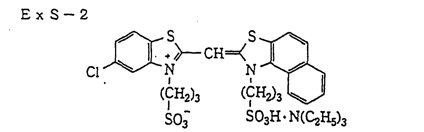
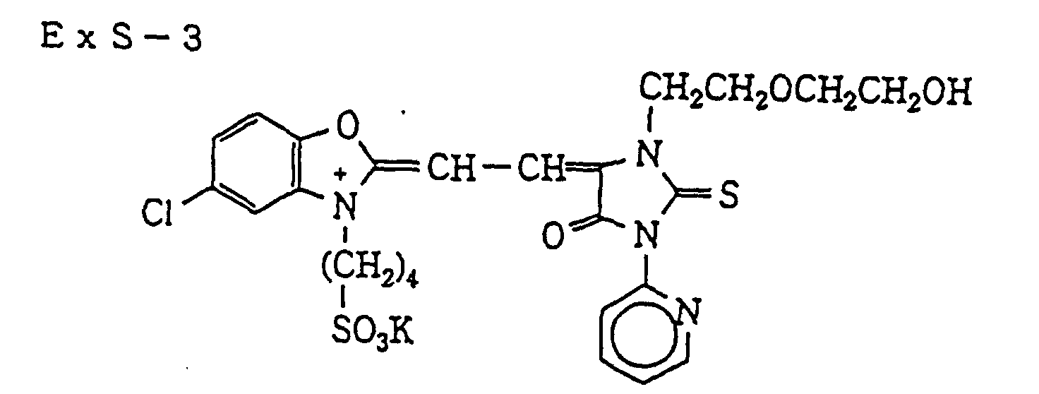

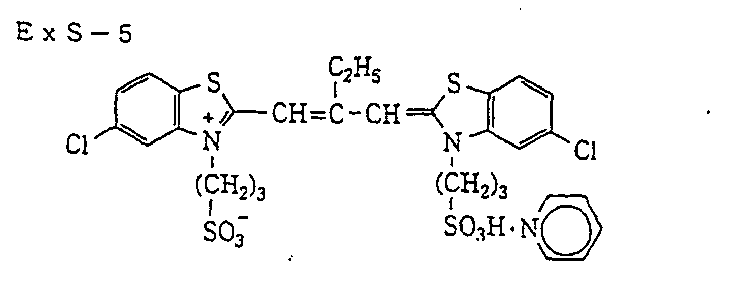
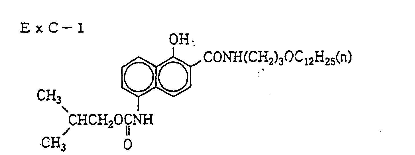
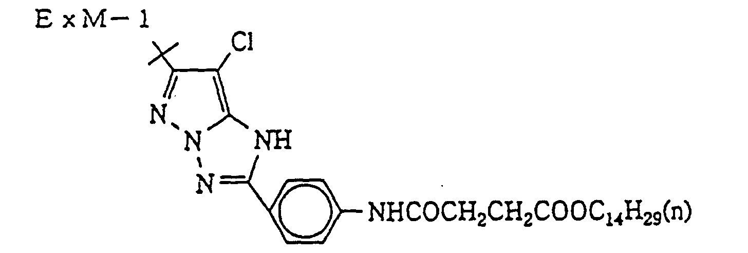
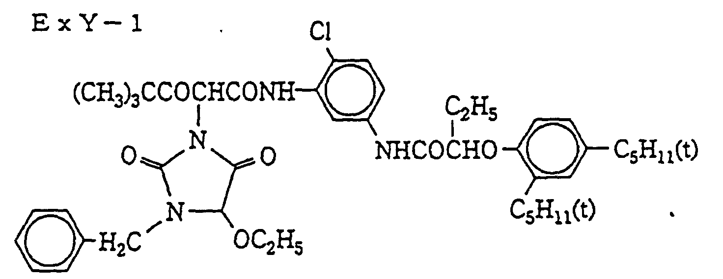




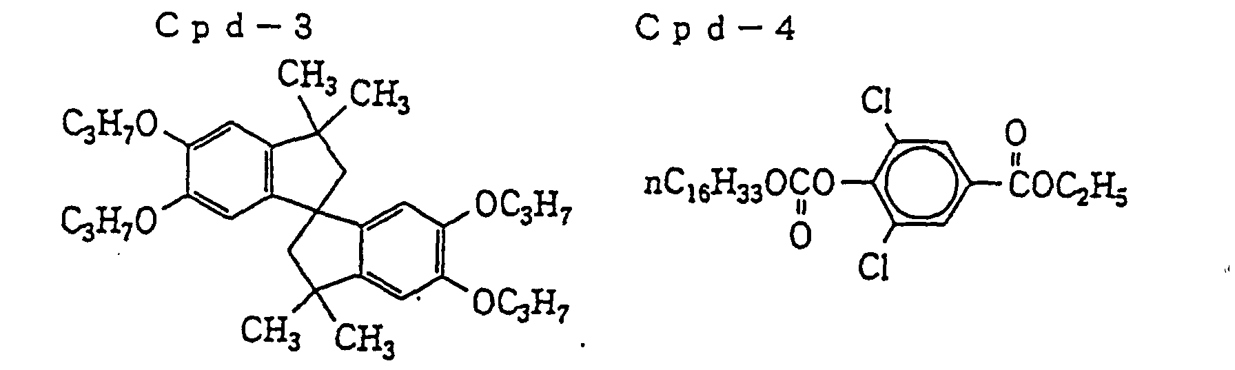
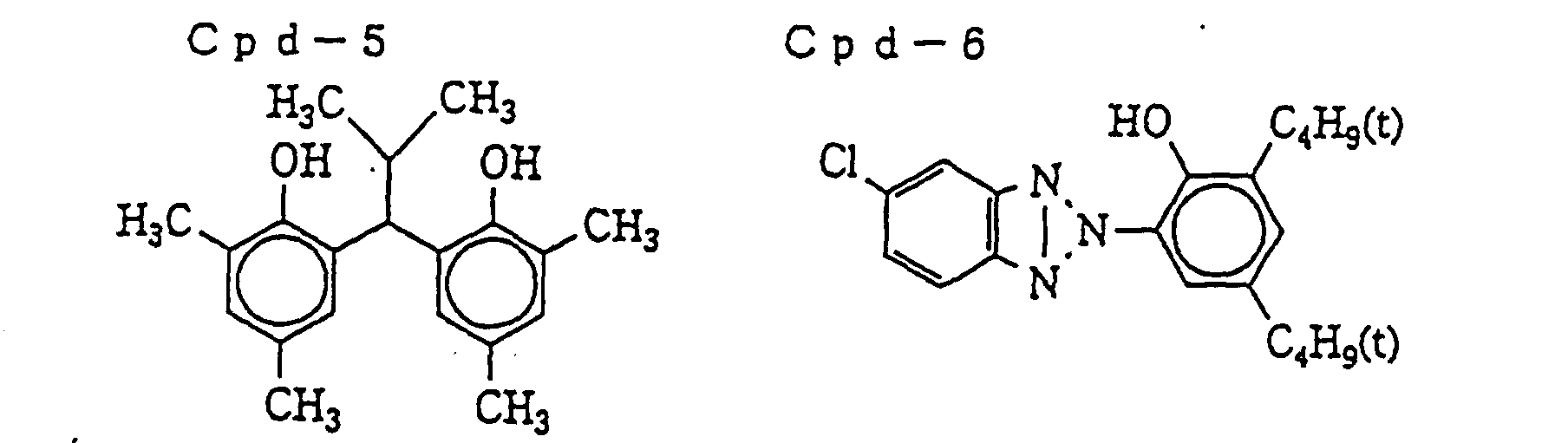


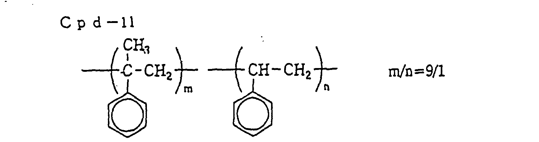
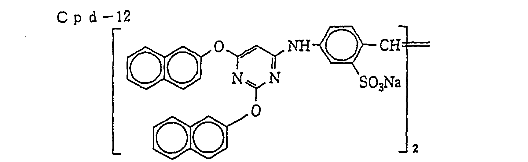

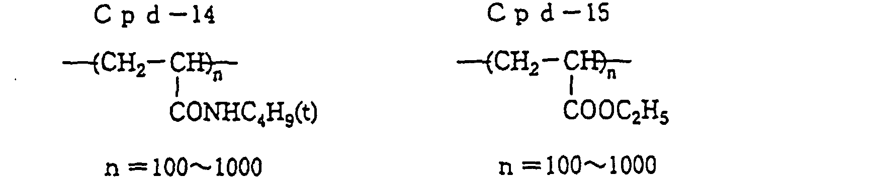

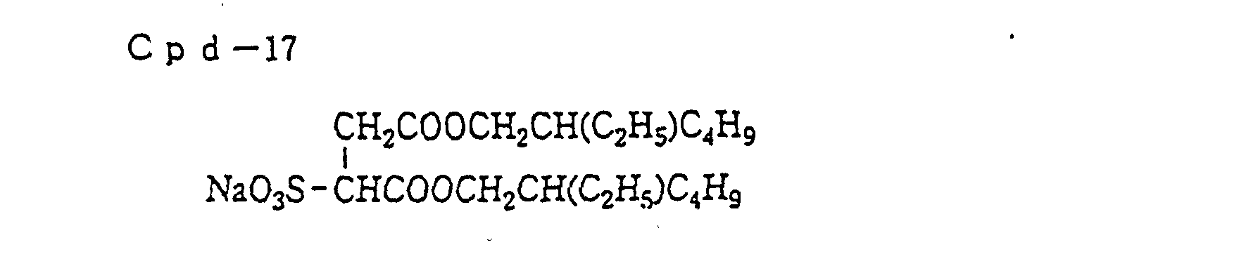


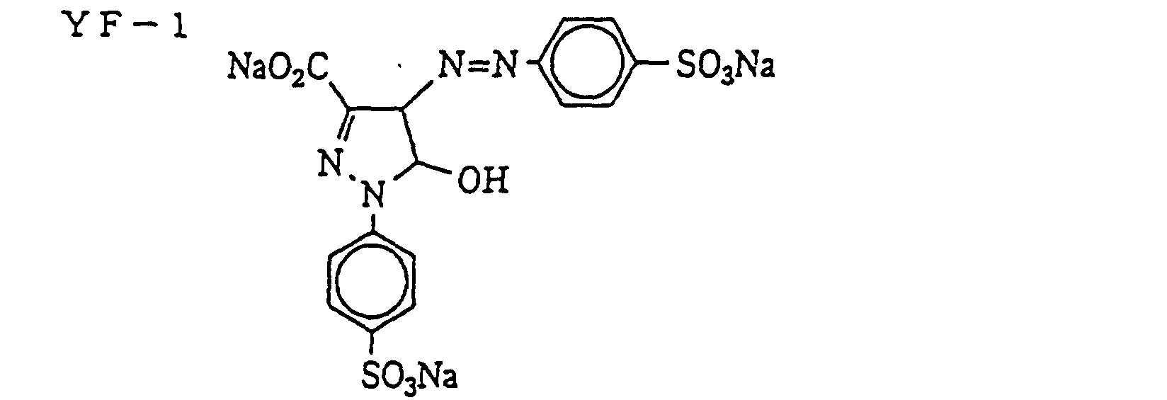

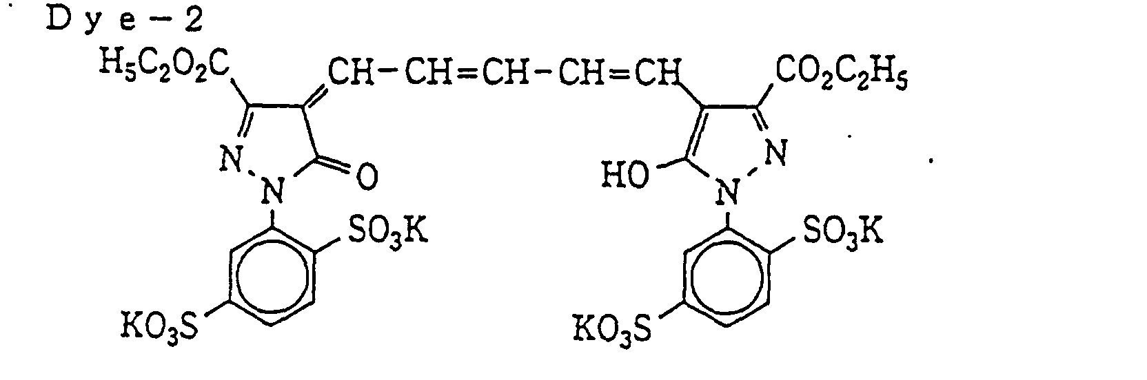
CH2=CHSO2CH2SO2CH=CH2
- Color Light-Sensitive Material 4B was prepared by adding 0.24 g/m2 of Infrared Dye-Forming Coupler (C-15) to the fifth layer (green-sensitive layer) and the seventh layer (blue-sensitive layer) of Color Light-Sensitive Material 4A.
- Each of Color Light-Sensitive Materials 3A, 3B, 4A and 4B prepared above was subjected to digital exposure of a pattern as shown in Fig. 2 from the emulsion surface thereof using an He-Cd laser (B light), a green semiconductor excited laser (using SHG) (G light) and an He-Ne laser (R light) while controlling the quantity of light so as to obtain hues in agreement with the color sensitivity of BGR of the silver halide light-sensitive material for color filter which will be described later. Each RGB pixel had a size of 250 µm × 175 µm, the black matrix (BM) area had a width of 25 µm, and the entire picture plane size was 15 cm × 10 cm. The BF area was exposed so as to form gray color having an ND of 0.3 for the purpose of controlling the quantity of light. Further, for the positioning in the after-processing, a dragonfly mark was also printed.
- Each exposed light-sensitive material was developed through the following steps and a master color filter having formed thereon BGR and gray colors in one operation was manufactured.
Processing Step Temperature (°C) Time Color development 38 90 s Bleach-fixing 38 90 s Water washing-1 25 30 s After-hardening 25 3 min. Water washing-2 25 40 s Water washing-3 25 90 s Drying 80 2 min. Color Developer: Water 800 ml D-Sorbitol 0.15 g Sodium naphthalenesulfonate·formalin condensate 0.15 g Pentasodium nitrilotris(methylenephosphonate) 1.8 g Diethylenetriaminepentaacetic acid 0.5 g 1-Hydroxyethylidene-1,1-diphosphonic acid 0.15 g Diethylene glycol 12.0 ml Benzyl alcohol 13.5 ml Potassium chloride 6.5 g Potassium bromide 0.1 g Potassium carbonate 30.0 g Sodium sulfite 2.4 g Disodium N,N-bis(sulfonatoethyl)-hydroxylamine 8.0 g Triethanolamine 6.0 g Benzotriazole 0.01 g N-Ethyl-N-(β-methanesulfonamidoethyl)-3-methyl-4- aminoaniline 3/2 sulfate monohydrate6.0 g Water to make 1 ℓ pH (25°C) 10.6 Bleach-Fixing Solution: Water 600 ml Ammonium thiosulfate (750 g/ℓ) 160 ml Ammonium sulfite 40.0 g Ammonium ethylenediaminetetraacetato ferrate 55.0 g Ethylenediaminetetraacetic acid 5.0 g Ammonium nitrate 10.0 g Ammonium bromide 25.0 g Water to make 1 ℓ pH (25°C) 6.0 After-Hardening Solution: Aqueous 4% glutaraldehyde solution Washing Water: Deionized water having an electric conductivity of 5 µS or less - A process for manufacturing a color filter using the master color filter prepared in Example 3 is described below.
- On a 100 µm-thick polyethylene terephthalate support having a back layer formed by coating carbon black dispersed in polyvinyl chloride, gelatin subbing was applied and thereon from the first to tenth layers each having the following structure were simultaneously coated one on another to prepare Color Light-Sensitive Material CF-1. The components and the coated amounts (unit: g/m2) are shown below. With respect to the silver halide emulsion, the coated amount is calculated in terms of silver. Unless otherwise indicated, the couplers and other compounds were the same as used in Example 3.
First Layer (release layer): Hydroxyethyl cellulose (HEC-SP500; produced by Daicel Chemical KK) 0.35 Terminal alkyl-modified polyvinyl, alcohol (average polymerization degree: 300) 0.08 Antistatic Agent (Cpd-1) 0.03 Second Layer (gelatin adjacent layer): Gelatin 0.60 Third Layer (blue-sensitive layer): Silver halide emulsion spectrally sensitized by Blue Sensitizing Dyes (ExS-1 and ExS-2) (AgBr30Cl70; average grain size: 0.35 µm) 0.33 Gelatin 1.00 Cyan Coupler (ExC-4) 0.57 Magenta Coupler (ExM-2) 0.05 Ultraviolet Absorbent (Cpd-6) 0.03 Ultraviolet Absorbent (Cpd-7) 0.08 High Boiling Point Solvent (Solv-1) 0.23 Fourth Layer (interlayer): Gelatin 0.38 Color Mixing Inhibitor (Cpd-2) 0.02 Color Mixing Inhibitor (Cpd-10) 0.09 High Boiling Point Solvent (Solv-1) 0.03 High Boiling Point Solvent (Solv-3) 0.01 Ultraviolet Absorbent (Cpd-8) 0.02 Ultraviolet Absorbent (Cpd-7) 0.02 Ultraviolet Absorbent (Cpd-6) 0.01 Ultraviolet Absorbent (Cpd-9) 0.02 Polymer (Cpd-11) 0.04 Yellow Dye (YF-1) 0.17 Fifth Layer (green-sensitive layer): Silver halide emulsion spectrally sensitized by Green Sensitizing Dye (ExS-3) (AgCl; average grain size: 0.18 µm) 0.71 Gelatin 1.39 Cyan Coupler (ExC-1) 0.34 Yellow Coupler (ExY-2) 0.47 Discoloration Inhibitor (Cpd-2) 0.01 Stain Inhibitor (Cpd-13) 0.01 High Boiling Point Solvent (Solv-1) 0.27 High Boiling Point Solvent (Solv-2) 0.39 Polymer (Cpd-14) 0.03 Sixth Layer (interlayer): Gelatin 0.38 Color Mixing Inhibitor (Cpd-2) 0.02 Color Mixing Inhibitor (Cpd-10) 0.09 High Boiling Point Solvent (Solv-1) 0.03 High Boiling Point Solvent (Solv-3) 0.01 Ultraviolet Absorbent (Cpd-8) 0.02 Ultraviolet Absorbent (Cpd-7) 0.02 Ultraviolet Absorbent (Cpd-6) 0.01 Ultraviolet Absorbent (Cpd-9) 0.02 Polymer (Cpd-11) 0.04 Irradiation Preventive Dye (Dye-1) 0.005 Irradiation Preventive Dye (Dye-2) 0.02 Seventh Layer (red-sensitive layer): Silver halide emulsion spectrally sensitized by Red Sensitizing Dyes (ExS-4 and ExS-5) (AgCl; average grain size: 0.18 µm) 0.36 Gelatin 1.33 Yellow Coupler (ExY-1) 0.61 Magenta Coupler (ExM-1) 0.15 Discoloration Inhibitor (Cpd-3) 0.11 Discoloration Inhibitor (Cpd-4) 0.005 Discoloration Inhibitor (Cpd-5) 0.01 High Boiling Point Solvent (Solv-4) 0.26 High Boiling Point Solvent (Solv-5) 0.14 High Boiling Point Solvent (Solv-6) 0.24 Polymer (Cpd-14) 0.03 Eighth Layer (interlayer): Gelatin 0.38 Color Mixing Inhibitor (Cpd-2) 0.02 Color Mixing Inhibitor (Cpd-10) 0.09 High Boiling Point Solvent (Solv-1) 0.03 High Boiling Point Solvent (Solv-3) 0.01 Ultraviolet Absorbent (Cpd-8) 0.02 Ultraviolet Absorbent (Cpd-7) 0.02 Ultraviolet Absorbent (Cpd-6) 0.01 Ultraviolet Absorbent (Cpd-9) 0.02 Polymer (Cpd-11) 0.04 Ninth Layer (infrared-sensitive layer): Silver halide emulsion spectrally sensitized by Infrared Sensitizing Dye (ExS-6) (AgBr30Cl70; average grain size: 0.2 µm) 0.44 Stabilizer (Cpd-12) 0.005 Gelatin 1.42 Cyan Coupler (ExC-2) 0.10 Yellow Coupler (ExY-1) 0.45 Magenta Coupler (ExM-1) 0.22 Discoloration Inhibitor (Cpd-3) 0.05 Discoloration Inhibitor (Cpd-4) 0.005 Discoloration Inhibitor (Cpd-5) 0.02 High Boiling Point Solvent (Solv-1) 0.28 High Boiling Point Solvent (Solv-2) 0.06 Stain Inhibitor (Cpd-13) 0.01 Polymer (Cpd-14) 0.03 Tenth Layer (protective layer): Gelatin 0.70 Antihalation dye (fine particle dispersion) 0.17 Carboxymethyl cellulose 0.05 Polymer (Cpd-15) 0.14 Surface Active Agent (Cpd-16) 0.03 Hardening Agent (H-1) 0.12 - In each layer, sodium dodecylbenzenesulfonate as an emulsification dispersion aid, ethyl acetate as an auxiliary solvent, Surface Active Agent (Cpd-17) as a coating aid and potassium polystyrenesulfonate as a thickening agent were used.


- A 0.7 mm-thick transparent alkali-free glass (24 cm × 32 cm) was used as the light-transmitting substrate. On the surface thereof, a 1:3 (by weight) mixture of gelatin and colloidal silica (average particle size: 7 to 9 mµ) having added thereto saponin as a surface active agent was coated. The dry thickness of the layer formed was 0.2 µm.
- The protective layer of Color Light-Sensitive Material CF-1 prepared above was adhered onto the coated surface of the light-transmitting substrate. The laminate obtained was traveled at a linear velocity of 0.45 m/min in a laminator where the temperature was set so that the temperature on the contact surface could be about 130°C. After the laminate was cooled almost to room temperature, the support of the light-sensitive material was peeled off together with the release layer from the emulsion surface. Then, second and upper emulsion layers were evenly bonded to the substrate and white spots were not observed.
- The thus-prepared substrate having emulsion layers was subjected to one-shot exposure from the emulsion surface side in a quartered face manner at an equal magnification through each master color filter prepared in Example 3 with its layer surface being put into contact with the substrate. The quatered face manner is as follows. The emulsion layer surface is imaginatively divided into four areas, and each area is exposed (by one-shot exposure) through a master color filter in order while other areas are masked, to prepare four color filters from one light-sensitive material. The exposed substrate was developed according to the following steps and as a result, four sets of a color filter having formed thereon BGR three colors and black color as shown in Fig. 3 in one operation were prepared.
Processing Step Temperature (°C) Time Pre-hardening 25 3 min. Water washing-1 25 1 min. Color development 38 80 s Stopping 25 20 s Bleach-fixing 38 90 s Water washing-2 25 40 s After-hardening 25 3 min. Water washing-3 25 90 s Drying 80 2 min. - The color developer, the bleach-fixing solution and the washing water were the same as used in Example 3 and the stopping solution was an aqueous 2% acetic acid solution.
Sodium sulfate (anhydrous) 160.0 g Sodium carbonate (anhydrous) 4.6 g Formalin (37%) 20.0 ml Water to make 1 ℓ pH (25°C) 9.5 - The color filters obtained each had a black matrix (BM) having a density of 2.5 or more. In the case where exposure was performed using a master color filter not containing an infrared dye (3A, 4A), the red picture element area was stained, whereas in the case where exposure was performed using a master color filter containing an infrared dye (3B, 4B), the red picture element area formed was free of color staining.
- An optically isotropic 100 µm-thick polyether sulfone substrate having laminated on the back surface thereof a polypropylene protective layer (thickness: 20 µm) was subjected to glow discharge treatment and thereon two layers of an SBR latex layer and a gelatin layer were coated to have good adhesion to the photographic emulsion layer. Further thereon, from the first to the eleventh layers each having the following structure were simultaneously coated one on another to prepare Color Light-Sensitive Material CF-2 for color filter. The components and the coating amounts (unit: g/m2) are shown below. With respect to the silver halide emulsion, the coating amount is calculated in terms of silver.
First Layer (antihalation layer): Gelatin 0.70 Antihalation dye (fine particle dispersion) 0.17 Carboxymethyl cellulose 0.05 Surface active agent (Cpd-16) 0.03 Hardening Agent (H-1) 0.05 Second Layer (infrared-sensitive layer): Silver halide emulsion spectrally sensitized by Infrared Sensitizing Dye (ExS-6) (AgBr30Cl70; average grain size: 0.2 µm) 0.44 Stabilizer (Cpd-12) 0.005 Gelatin 1.42 Cyan Coupler (ExC-4) 0.10 Yellow Coupler (ExY-1) 0.45 Magenta Coupler (ExM-1) 0.22 Discoloration Inhibitor (Cpd-3) 0.05 High Boiling Point Solvent (Solv-1) 0.28 High Boiling Point Solvent (Solv-2) 0.6 Polymer (Cpd-14) 0.03 Third Layer (interlayer): Gelatin 0.38 Discoloration Inhibitor (Cpd-2) 0.02 Discoloration Inhibitor (Cpd-10) 0.09 High Boiling Point Solvent (Solv-1) 0.03 High Boiling Point Solvent (Solv-3) 0.01 Ultraviolet Absorbent (Cpd-8) 0.02 Ultraviolet Absorbent (Cpd-7) 0.02 Ultraviolet Absorbent (Cpd-6) 0.01 Ultraviolet Absorbent (Cpd-9) 0.02 Polymer (Cpd-11) 0.04 Irradiation Preventive Dye (Dye-3) 0.04 Fourth Layer (first red-sensitive layer): Silver halide emulsion spectrally sensitized by Red Sensitizing Dyes (ExS-4 and ExS-5) (AgCl; average grain size: 0.18 µm) 0.11 Gelatin 0.70 Magenta Coupler (ExM-1) 0.15 Discoloration Inhibitor (Cpd-3) 0.08 Discoloration Inhibitor (Cpd-5) 0.01 High Boiling Point Solvent (Solv-4) 0.28 High Boiling Point Solvent (Solv-5) 0.14 Polymer (Cpd-11) 0.08 Fifth Layer (second red-sensitive layer): Silver halide emulsion spectrally sensitized by Red Sensitizing Dyes (ExS-4 and ExS-5) (AgCl; average grain size: 0.18 µm) 0.26 Gelatin 0.64 Yellow Coupler (ExY-1) 0.61 Stain Inhibitor (Cpd-13) 0.08 Discoloration Inhibitor (Cpd-5) 0.04 High Boiling Point Solvent (Solv-6) 0.24 Polymer (Cpd-14) 0.08 Sixth Layer (interlayer): Gelatin 0.38 Irradiation Preventive Dye (Dye-1) 0.005 Irradiation Preventive Dye (Dye-2) 0.02 Seventh Layer (first green-sensitive layer): Silver halide emulsion spectrally sensitized by Green Sensitizing Dye (ExS-3) (AgCl; average grain size: 0.18 µm) 0.23 Gelatin 0.62 Yellow Coupler (ExY-1) 0.54 Discoloration Inhibitor (Cpd-5) 0.03 Stain Inhibitor (Cpd-13) 0.07 High Boiling Point Solvent (Solv-6) 0.22 Polymer (Cpd-14) 0.07 Eighth Layer (second green-sensitive layer): Silver halide emulsion spectrally sensitized by Green Sensitizing Dye (ExS-3) (AgCl; average grain size: 0.18 µm) 0.19 Gelatin 0.68 Cyan Coupler (ExC-3) 0.20 Cyan Coupler (EXC-2) 0.03 High Boiling Point Solvent (Solv-7) 0.51 Polymer (Cpd-14) 0.02 Ninth Layer (interlayer): Gelatin 0.38 Color Mixing Inhibitor (Cpd-2) 0.02 Color Mixing Inhibitor (Cpd-10) 0.09 High Boiling Point Solvent (Solv-1) 0.03 High Boiling Point Solvent (Solv-3) 0.01 Ultraviolet Absorbent (Cpd-8) 0.02 Ultraviolet Absorbent (Cpd-7) 0.02 Ultraviolet Absorbent (Cpd-6) 0.01 Ultraviolet Absorbent (Cpd-9) 0.02 Polymer (Cpd-11) 0.04 Yellow Dye (YF-1) 0.17 Tenth Layer (blue-sensitive layer): Silver halide emulsion spectrally sensitized by Blue Sensitizing Dyes (ExS-1 and ExS-2) (AgBr30Cl70; average grain size: 0.35 µm) 0.33 Gelatin 0.98 Cyan Coupler (ExC-4) 0.57 Magenta Coupler (ExM-2) 0.05 Ultraviolet Absorbent (Cpd-6) 0.03 Ultraviolet Absorbent (Cpd-7) 0.08 High Boiling Point Solvent (Solv-1) 0.23 Hardening Agent (H-1) 0.08 Eleventh Layer (protective layer): Gelatin (acid-processed) 0.65 Antistatic agent (Cpd-1) 0.01 Snowtex-O (produced by Nissan Kagaku Kogyo KK) 0.19 - In each layer, sodium dodecylbenzenesulfonate as an emulsification dispersion aid, ethyl acetate as an auxiliary solvent, Surface Active Agent (Cpd-17) as a coating aid and potassium polystyrenesulfonate as a thickening agent were used.
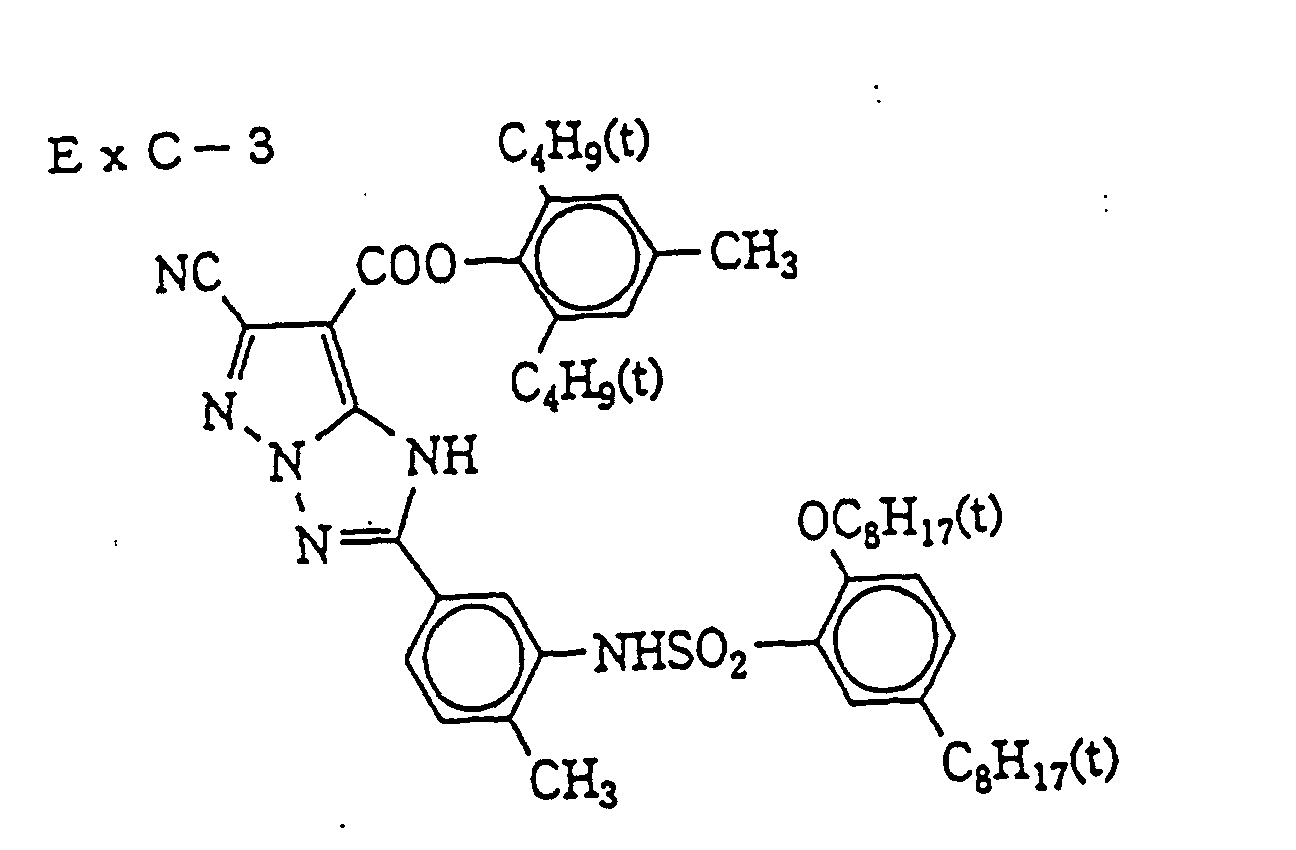
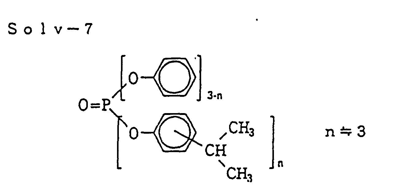
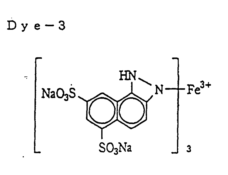
- Color Light-Sensitive Material CF-2 prepared above was subjected to one-shot exposure at an equal magnification or a half reduction through each of the master color filters prepared in Example 3 using a camera for photomechanical process, and then to color development according to the following steps. As a result, color filters each having BGR three colors and black color formed in one operation were prepared. The processing solutions were the same as those used in Example 3.
Processing Step Temperature (°C) Time Color development 38 80 s Bleach-fixing 38 90 s Water washing-1 25 1 min. After-hardening 25 3 min. Water washing-2 25 2 min. Drying 80 2 min. - Similarly to Example 4, in the case where exposure was performed using a master color filter containing an infrared dye (3B, 4B), color staining was not generated and the BM had a high density.
- On the color filter layer obtained, the following composition was coated to have a dry thickness of 2.5 µm, then dried and hardened with ultraviolet rays to form a protective layer. The resulting color filter was good in the adhesion between the color filter layer and the protective layer and had good resistance against chemicals. The picture element by the reduction exposure was small in the roughness as compared with the picture element by the exposure at an equal magnification. Using the thus-manufactured color filter, a color liquid crystal panel comprising a plastic film substrate was produced.
Formulation of Overcoat Composition: Monomer (1) 77.4 wt% Monomer (2) 7.7 Polymer CAB 531 (produced by Eastman Chemical) 11.7 Photopolymerization initiator 2.4 Sensitizer 0.8 Diluting solvent (MEK) for coating - -

-

-

-

- A master color filter having any pixel pattern can be easily manufactured using a silver halide color light-sensitive material containing an infrared dye-forming coupler. By subjecting a silver halide color light-sensitive material for color filter to one-shot exposure using this master color filter and then to one-time development processing, a color filter can be easily manufactured within a short time. The color filter obtained has red, green and blue color areas excellent in the spectral characteristics and a black matrix (BM) having a high optical density.
Claims (4)
- A process for producing a color filter having red, green and blue pixel patterns and a black matrix comprising the steps of:characterized in that(1) providing a master color filter having pixel patterns colored to red, green and blue, respectively, and having a substantially colorless area corresponding to the black matrix, by a process comprising:exposing a first silver halide color light-sensitive material comprising a transparent support having thereon at least three silver halide emulsion layers having different color sensitivity from each other; andcolor developing and desilvering said exposed light-sensitive material;said first silver halide color light-sensitive material comprises' at least a yellow coupler-containing silver halide emulsion layer, a magenta coupler-containing silver halide emulsion layer and a cyan coupler-containing silver halide emulsion layer;(2) providing a second silver halide color light-sensitive material comprising a transparent substrate having thereon at least:a rsd-sensitive silver halide emulsion layer containing a coupler which is sensitive to the red color of said master color filter and which forms a red color;a green-sensitive silver halide emulsion layer containing a coupler which is sensitive to the green color of said master color filter and which forms a green color;a blue-sensitive silver halide emulsion layer containing a coupler which is sensitive to the blue color of said master color filter and which forms a blue color; andan infrared-sensitive emulsion;(3) one-shot exposing said second silver halide color light-sensitive material with white light through the master color filter; and then(4) color developing and desilvering said one-shot exposed light-sensitive materialeither at least one of said yellow coupler containing silver halide emulsion layer and said magenta coupler-containing silver halide emulsion layer contains an infrared dye-forming coupler, orsaid first silver halide color light-sensitive material further comprises a silver halide emulsion layer which contains an infrared dye-forming coupler and which has the same sensitivity as that of either or both of said yellow coupler-containing silver halide emulsion layer and said magenta coupler-containing silver halide emulsion layer.
- The process as claimed in claim 1, wherein said pattern exposure of said first silver halide color light-sensitive material is carried out using a laser ray.
- The process as claimed in claim 1 or 2, wherein the one-shot exposure of said second silver halide color light-sensitive material is carried out in a reduced magnification manner.
- The process as claimed in any of claims 1 to 3 wherein said infrared dye-forming coupler is represented by the following formula (I):wherein L represents -CO- or -SO2-, R1 represents an alkyl group, an aryl group or a heterocyclic group, R2 represents a hydrogen atom, an alkyl group or an aryl group, R3 represents a substituent, n represents 0, 1, 2, 3 or 4, and X represents a hydrogen atom or a group capable of splitting off upon coupling with an oxidation product of a developing agent.

Applications Claiming Priority (9)
| Application Number | Priority Date | Filing Date | Title |
|---|---|---|---|
| JP34115296 | 1996-12-20 | ||
| JP34115296 | 1996-12-20 | ||
| JP341152/96 | 1996-12-20 | ||
| JP24751/97 | 1997-02-07 | ||
| JP2475197 | 1997-02-07 | ||
| JP2475197A JPH10232307A (en) | 1996-12-20 | 1997-02-07 | Production of color filter |
| JP85199/97 | 1997-04-03 | ||
| JP8519997 | 1997-04-03 | ||
| JP8519997 | 1997-04-03 |
Publications (3)
| Publication Number | Publication Date |
|---|---|
| EP0849630A2 EP0849630A2 (en) | 1998-06-24 |
| EP0849630A3 EP0849630A3 (en) | 1999-03-03 |
| EP0849630B1 true EP0849630B1 (en) | 2001-11-21 |
Family
ID=27284769
Family Applications (1)
| Application Number | Title | Priority Date | Filing Date |
|---|---|---|---|
| EP97122552A Expired - Lifetime EP0849630B1 (en) | 1996-12-20 | 1997-12-19 | Process for producing color filter |
Country Status (3)
| Country | Link |
|---|---|
| EP (1) | EP0849630B1 (en) |
| AT (1) | ATE209367T1 (en) |
| DE (1) | DE69708448T2 (en) |
Family Cites Families (3)
| Publication number | Priority date | Publication date | Assignee | Title |
|---|---|---|---|---|
| EP0396824B1 (en) * | 1989-04-13 | 1994-08-31 | Agfa-Gevaert N.V. | Process for the production of a multicolour liquid crystal display device |
| JP3357482B2 (en) * | 1994-11-09 | 2002-12-16 | 富士写真フイルム株式会社 | Negative-type silver halide photosensitive material for color filters |
| EP0740201A1 (en) * | 1995-04-24 | 1996-10-30 | Agfa-Gevaert N.V. | Production of matching color prints by establishing suitable color master |
-
1997
- 1997-12-19 EP EP97122552A patent/EP0849630B1/en not_active Expired - Lifetime
- 1997-12-19 DE DE69708448T patent/DE69708448T2/en not_active Expired - Lifetime
- 1997-12-19 AT AT97122552T patent/ATE209367T1/en not_active IP Right Cessation
Also Published As
| Publication number | Publication date |
|---|---|
| ATE209367T1 (en) | 2001-12-15 |
| DE69708448T2 (en) | 2002-05-16 |
| EP0849630A2 (en) | 1998-06-24 |
| EP0849630A3 (en) | 1999-03-03 |
| DE69708448D1 (en) | 2002-01-03 |
Similar Documents
| Publication | Publication Date | Title |
|---|---|---|
| US5776643A (en) | Light-sensitive material for color filter and process for producing color filter using the same | |
| EP0713137B1 (en) | Silver halide photosensitive material for color filter and method for producing color filter using the same | |
| US5571663A (en) | Silver halide light-sensitive material and color filter | |
| US5981111A (en) | Process for manufacturing color filter using silver halide light-sensitive material | |
| EP0849630A2 (en) | Process for producing color filter | |
| US5817440A (en) | Silver halide photosensitive material for color filter and method for producing color filter using the same | |
| US5885736A (en) | Preparation method of color filter using a silver halide light sensitive material | |
| EP0662635B1 (en) | Process for producing colour filter | |
| JP3356872B2 (en) | Color filter and manufacturing method thereof | |
| JPH10333295A (en) | Silver halide photographic sensitive mateal nd color filter forming method by using same | |
| JPH112713A (en) | Production of color filter base plate for color display device | |
| JPH08248219A (en) | Production of color filter | |
| JP2003066217A (en) | Color filter and method for manufacturing color filter | |
| JPH09288208A (en) | Silver halide photosensitive material for color filter and formation of color filter | |
| JPH10232307A (en) | Production of color filter | |
| JPH09204026A (en) | Silver halide color photosensitive material and production of color filter using the material | |
| JPH09146236A (en) | Silver halide photosensitive material and formation of color filter using the same | |
| JPH0980219A (en) | Silver halide photosensitive material for color filter and formation of color filter using the same | |
| JPH1195023A (en) | Color filter and manufacture thereof | |
| JPH09218494A (en) | Silver halide color photosensitive material and production of color filter using that | |
| JP3852990B2 (en) | Method for producing a color filter using a silver halide photosensitive material | |
| JPH09145909A (en) | Color filter and color liquid crystal display device using that | |
| JPH09204027A (en) | Silver halide color photosensitive material and production of color filter using the material | |
| JPH09189986A (en) | Silver halide color photographic sensitive material and method for forming color filter by using same | |
| JPH0980222A (en) | Silver halide photosensitive material for color filter and formation of color filter using the same |
Legal Events
| Date | Code | Title | Description |
|---|---|---|---|
| PUAI | Public reference made under article 153(3) epc to a published international application that has entered the european phase |
Free format text: ORIGINAL CODE: 0009012 |
|
| AK | Designated contracting states |
Kind code of ref document: A2 Designated state(s): AT BE CH DE DK ES FI FR GB GR IE IT LI LU MC NL PT SE |
|
| AX | Request for extension of the european patent |
Free format text: AL;LT;LV;MK;RO;SI |
|
| PUAL | Search report despatched |
Free format text: ORIGINAL CODE: 0009013 |
|
| AK | Designated contracting states |
Kind code of ref document: A3 Designated state(s): AT BE CH DE DK ES FI FR GB GR IE IT LI LU MC NL PT SE |
|
| AX | Request for extension of the european patent |
Free format text: AL;LT;LV;MK;RO;SI |
|
| 17P | Request for examination filed |
Effective date: 19990611 |
|
| AKX | Designation fees paid |
Free format text: AT BE CH DE DK ES FI FR GB GR IE IT LI LU MC NL PT SE |
|
| 17Q | First examination report despatched |
Effective date: 19991110 |
|
| GRAG | Despatch of communication of intention to grant |
Free format text: ORIGINAL CODE: EPIDOS AGRA |
|
| GRAG | Despatch of communication of intention to grant |
Free format text: ORIGINAL CODE: EPIDOS AGRA |
|
| GRAH | Despatch of communication of intention to grant a patent |
Free format text: ORIGINAL CODE: EPIDOS IGRA |
|
| GRAH | Despatch of communication of intention to grant a patent |
Free format text: ORIGINAL CODE: EPIDOS IGRA |
|
| GRAA | (expected) grant |
Free format text: ORIGINAL CODE: 0009210 |
|
| AK | Designated contracting states |
Kind code of ref document: B1 Designated state(s): AT BE CH DE DK ES FI FR GB GR IE IT LI LU MC NL PT SE |
|
| PG25 | Lapsed in a contracting state [announced via postgrant information from national office to epo] |
Ref country code: NL Free format text: LAPSE BECAUSE OF FAILURE TO SUBMIT A TRANSLATION OF THE DESCRIPTION OR TO PAY THE FEE WITHIN THE PRESCRIBED TIME-LIMIT Effective date: 20011121 Ref country code: LI Free format text: LAPSE BECAUSE OF FAILURE TO SUBMIT A TRANSLATION OF THE DESCRIPTION OR TO PAY THE FEE WITHIN THE PRESCRIBED TIME-LIMIT Effective date: 20011121 Ref country code: IT Free format text: LAPSE BECAUSE OF FAILURE TO SUBMIT A TRANSLATION OF THE DESCRIPTION OR TO PAY THE FEE WITHIN THE PRESCRIBED TIME-LIMIT;WARNING: LAPSES OF ITALIAN PATENTS WITH EFFECTIVE DATE BEFORE 2007 MAY HAVE OCCURRED AT ANY TIME BEFORE 2007. THE CORRECT EFFECTIVE DATE MAY BE DIFFERENT FROM THE ONE RECORDED. Effective date: 20011121 Ref country code: GR Free format text: LAPSE BECAUSE OF FAILURE TO SUBMIT A TRANSLATION OF THE DESCRIPTION OR TO PAY THE FEE WITHIN THE PRESCRIBED TIME-LIMIT Effective date: 20011121 Ref country code: FR Free format text: LAPSE BECAUSE OF FAILURE TO SUBMIT A TRANSLATION OF THE DESCRIPTION OR TO PAY THE FEE WITHIN THE PRESCRIBED TIME-LIMIT Effective date: 20011121 Ref country code: FI Free format text: LAPSE BECAUSE OF FAILURE TO SUBMIT A TRANSLATION OF THE DESCRIPTION OR TO PAY THE FEE WITHIN THE PRESCRIBED TIME-LIMIT Effective date: 20011121 Ref country code: CH Free format text: LAPSE BECAUSE OF FAILURE TO SUBMIT A TRANSLATION OF THE DESCRIPTION OR TO PAY THE FEE WITHIN THE PRESCRIBED TIME-LIMIT Effective date: 20011121 Ref country code: BE Free format text: LAPSE BECAUSE OF FAILURE TO SUBMIT A TRANSLATION OF THE DESCRIPTION OR TO PAY THE FEE WITHIN THE PRESCRIBED TIME-LIMIT Effective date: 20011121 Ref country code: AT Free format text: LAPSE BECAUSE OF FAILURE TO SUBMIT A TRANSLATION OF THE DESCRIPTION OR TO PAY THE FEE WITHIN THE PRESCRIBED TIME-LIMIT Effective date: 20011121 |
|
| REF | Corresponds to: |
Ref document number: 209367 Country of ref document: AT Date of ref document: 20011215 Kind code of ref document: T |
|
| REG | Reference to a national code |
Ref country code: CH Ref legal event code: EP |
|
| PG25 | Lapsed in a contracting state [announced via postgrant information from national office to epo] |
Ref country code: MC Free format text: LAPSE BECAUSE OF NON-PAYMENT OF DUE FEES Effective date: 20011219 Ref country code: LU Free format text: LAPSE BECAUSE OF NON-PAYMENT OF DUE FEES Effective date: 20011219 Ref country code: IE Free format text: LAPSE BECAUSE OF FAILURE TO SUBMIT A TRANSLATION OF THE DESCRIPTION OR TO PAY THE FEE WITHIN THE PRESCRIBED TIME-LIMIT Effective date: 20011219 |
|
| REG | Reference to a national code |
Ref country code: IE Ref legal event code: FG4D |
|
| REG | Reference to a national code |
Ref country code: GB Ref legal event code: IF02 |
|
| REF | Corresponds to: |
Ref document number: 69708448 Country of ref document: DE Date of ref document: 20020103 |
|
| PG25 | Lapsed in a contracting state [announced via postgrant information from national office to epo] |
Ref country code: SE Free format text: LAPSE BECAUSE OF FAILURE TO SUBMIT A TRANSLATION OF THE DESCRIPTION OR TO PAY THE FEE WITHIN THE PRESCRIBED TIME-LIMIT Effective date: 20020221 Ref country code: PT Free format text: LAPSE BECAUSE OF FAILURE TO SUBMIT A TRANSLATION OF THE DESCRIPTION OR TO PAY THE FEE WITHIN THE PRESCRIBED TIME-LIMIT Effective date: 20020221 Ref country code: GB Free format text: LAPSE BECAUSE OF NON-PAYMENT OF DUE FEES Effective date: 20020221 Ref country code: DK Free format text: LAPSE BECAUSE OF FAILURE TO SUBMIT A TRANSLATION OF THE DESCRIPTION OR TO PAY THE FEE WITHIN THE PRESCRIBED TIME-LIMIT Effective date: 20020221 |
|
| NLV1 | Nl: lapsed or annulled due to failure to fulfill the requirements of art. 29p and 29m of the patents act | ||
| PG25 | Lapsed in a contracting state [announced via postgrant information from national office to epo] |
Ref country code: ES Free format text: LAPSE BECAUSE OF FAILURE TO SUBMIT A TRANSLATION OF THE DESCRIPTION OR TO PAY THE FEE WITHIN THE PRESCRIBED TIME-LIMIT Effective date: 20020530 |
|
| REG | Reference to a national code |
Ref country code: CH Ref legal event code: PL |
|
| PLBE | No opposition filed within time limit |
Free format text: ORIGINAL CODE: 0009261 |
|
| STAA | Information on the status of an ep patent application or granted ep patent |
Free format text: STATUS: NO OPPOSITION FILED WITHIN TIME LIMIT |
|
| REG | Reference to a national code |
Ref country code: IE Ref legal event code: MM4A |
|
| EN | Fr: translation not filed | ||
| GBPC | Gb: european patent ceased through non-payment of renewal fee |
Effective date: 20020221 |
|
| 26N | No opposition filed | ||
| PGFP | Annual fee paid to national office [announced via postgrant information from national office to epo] |
Ref country code: DE Payment date: 20101124 Year of fee payment: 14 |
|
| REG | Reference to a national code |
Ref country code: DE Ref legal event code: R119 Ref document number: 69708448 Country of ref document: DE Effective date: 20120703 |
|
| PG25 | Lapsed in a contracting state [announced via postgrant information from national office to epo] |
Ref country code: DE Free format text: LAPSE BECAUSE OF NON-PAYMENT OF DUE FEES Effective date: 20120703 |