EP0849111B1 - Supply unit for an electric vehicle - Google Patents
Supply unit for an electric vehicle Download PDFInfo
- Publication number
- EP0849111B1 EP0849111B1 EP96830637A EP96830637A EP0849111B1 EP 0849111 B1 EP0849111 B1 EP 0849111B1 EP 96830637 A EP96830637 A EP 96830637A EP 96830637 A EP96830637 A EP 96830637A EP 0849111 B1 EP0849111 B1 EP 0849111B1
- Authority
- EP
- European Patent Office
- Prior art keywords
- direct
- operating mode
- switches
- direct voltage
- energy source
- Prior art date
- Legal status (The legal status is an assumption and is not a legal conclusion. Google has not performed a legal analysis and makes no representation as to the accuracy of the status listed.)
- Expired - Lifetime
Links
Images


Classifications
-
- B—PERFORMING OPERATIONS; TRANSPORTING
- B60—VEHICLES IN GENERAL
- B60L—PROPULSION OF ELECTRICALLY-PROPELLED VEHICLES; SUPPLYING ELECTRIC POWER FOR AUXILIARY EQUIPMENT OF ELECTRICALLY-PROPELLED VEHICLES; ELECTRODYNAMIC BRAKE SYSTEMS FOR VEHICLES IN GENERAL; MAGNETIC SUSPENSION OR LEVITATION FOR VEHICLES; MONITORING OPERATING VARIABLES OF ELECTRICALLY-PROPELLED VEHICLES; ELECTRIC SAFETY DEVICES FOR ELECTRICALLY-PROPELLED VEHICLES
- B60L53/00—Methods of charging batteries, specially adapted for electric vehicles; Charging stations or on-board charging equipment therefor; Exchange of energy storage elements in electric vehicles
- B60L53/20—Methods of charging batteries, specially adapted for electric vehicles; Charging stations or on-board charging equipment therefor; Exchange of energy storage elements in electric vehicles characterised by converters located in the vehicle
-
- H—ELECTRICITY
- H02—GENERATION; CONVERSION OR DISTRIBUTION OF ELECTRIC POWER
- H02J—CIRCUIT ARRANGEMENTS OR SYSTEMS FOR SUPPLYING OR DISTRIBUTING ELECTRIC POWER; SYSTEMS FOR STORING ELECTRIC ENERGY
- H02J7/00—Circuit arrangements for charging or depolarising batteries or for supplying loads from batteries
- H02J7/02—Circuit arrangements for charging or depolarising batteries or for supplying loads from batteries for charging batteries from ac mains by converters
-
- H—ELECTRICITY
- H02—GENERATION; CONVERSION OR DISTRIBUTION OF ELECTRIC POWER
- H02J—CIRCUIT ARRANGEMENTS OR SYSTEMS FOR SUPPLYING OR DISTRIBUTING ELECTRIC POWER; SYSTEMS FOR STORING ELECTRIC ENERGY
- H02J2207/00—Indexing scheme relating to details of circuit arrangements for charging or depolarising batteries or for supplying loads from batteries
- H02J2207/20—Charging or discharging characterised by the power electronics converter
-
- Y—GENERAL TAGGING OF NEW TECHNOLOGICAL DEVELOPMENTS; GENERAL TAGGING OF CROSS-SECTIONAL TECHNOLOGIES SPANNING OVER SEVERAL SECTIONS OF THE IPC; TECHNICAL SUBJECTS COVERED BY FORMER USPC CROSS-REFERENCE ART COLLECTIONS [XRACs] AND DIGESTS
- Y02—TECHNOLOGIES OR APPLICATIONS FOR MITIGATION OR ADAPTATION AGAINST CLIMATE CHANGE
- Y02T—CLIMATE CHANGE MITIGATION TECHNOLOGIES RELATED TO TRANSPORTATION
- Y02T10/00—Road transport of goods or passengers
- Y02T10/60—Other road transportation technologies with climate change mitigation effect
- Y02T10/70—Energy storage systems for electromobility, e.g. batteries
-
- Y—GENERAL TAGGING OF NEW TECHNOLOGICAL DEVELOPMENTS; GENERAL TAGGING OF CROSS-SECTIONAL TECHNOLOGIES SPANNING OVER SEVERAL SECTIONS OF THE IPC; TECHNICAL SUBJECTS COVERED BY FORMER USPC CROSS-REFERENCE ART COLLECTIONS [XRACs] AND DIGESTS
- Y02—TECHNOLOGIES OR APPLICATIONS FOR MITIGATION OR ADAPTATION AGAINST CLIMATE CHANGE
- Y02T—CLIMATE CHANGE MITIGATION TECHNOLOGIES RELATED TO TRANSPORTATION
- Y02T10/00—Road transport of goods or passengers
- Y02T10/60—Other road transportation technologies with climate change mitigation effect
- Y02T10/7072—Electromobility specific charging systems or methods for batteries, ultracapacitors, supercapacitors or double-layer capacitors
-
- Y—GENERAL TAGGING OF NEW TECHNOLOGICAL DEVELOPMENTS; GENERAL TAGGING OF CROSS-SECTIONAL TECHNOLOGIES SPANNING OVER SEVERAL SECTIONS OF THE IPC; TECHNICAL SUBJECTS COVERED BY FORMER USPC CROSS-REFERENCE ART COLLECTIONS [XRACs] AND DIGESTS
- Y02—TECHNOLOGIES OR APPLICATIONS FOR MITIGATION OR ADAPTATION AGAINST CLIMATE CHANGE
- Y02T—CLIMATE CHANGE MITIGATION TECHNOLOGIES RELATED TO TRANSPORTATION
- Y02T90/00—Enabling technologies or technologies with a potential or indirect contribution to GHG emissions mitigation
- Y02T90/10—Technologies relating to charging of electric vehicles
- Y02T90/12—Electric charging stations
-
- Y—GENERAL TAGGING OF NEW TECHNOLOGICAL DEVELOPMENTS; GENERAL TAGGING OF CROSS-SECTIONAL TECHNOLOGIES SPANNING OVER SEVERAL SECTIONS OF THE IPC; TECHNICAL SUBJECTS COVERED BY FORMER USPC CROSS-REFERENCE ART COLLECTIONS [XRACs] AND DIGESTS
- Y02—TECHNOLOGIES OR APPLICATIONS FOR MITIGATION OR ADAPTATION AGAINST CLIMATE CHANGE
- Y02T—CLIMATE CHANGE MITIGATION TECHNOLOGIES RELATED TO TRANSPORTATION
- Y02T90/00—Enabling technologies or technologies with a potential or indirect contribution to GHG emissions mitigation
- Y02T90/10—Technologies relating to charging of electric vehicles
- Y02T90/14—Plug-in electric vehicles
Definitions
- the present invention relates to a supply unit for an electric vehicle.
- an electric vehicle comprises a number of operating units, including a direct voltage energy source (normally comprising a number of batteries), an electric motor, and a supply unit for controlling energy supply from the energy source to the electric motor on the basis of a number of control signals; as well as various auxiliary units, e.g. for generating energy locally, recharging the direct voltage energy source, supplying electric equipment on the vehicle, etc.
- a direct voltage energy source normally comprising a number of batteries
- an electric motor normally comprising a number of batteries
- a supply unit for controlling energy supply from the energy source to the electric motor on the basis of a number of control signals
- various auxiliary units e.g. for generating energy locally, recharging the direct voltage energy source, supplying electric equipment on the vehicle, etc.
- the various units of an electric vehicle are formed inside boxes, which are physically separate from one another and interconnected by electric power and signal cables extending between the boxes.
- a supply unit for an electric vehicle as claimed in Claim 1.
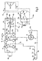
- Number 1 in Figure 1 indicates a supply unit for an electric vehicle.
- Unit 1 comprises a rechargeable direct voltage energy source 4 (shown by the dotted line) for supplying - via a reconfigurable circuit 6 operating in a first supply mode - an electric motor 8 for driving a vehicle (not shown).
- Unit 1 also comprises a device 10 connectable to an alternating voltage source (e.g. a 220 V, 50 Hz mains voltage) for supplying said voltage to reconfigurable circuit 6, which, when operating in a second battery-charge mode, rectifies the mains voltage to charge direct voltage energy source 4.
- an alternating voltage source e.g. a 220 V, 50 Hz mains voltage
- energy source 4 comprises a number of rechargeable batteries 13 (in the example shown, only two are indicated for the sake of simplicity) arranged in series, and which together supply a direct supply voltage V (e.g. of 240 V) between the positive output terminal 15 and, respectively, the negative output terminal 16 of energy source 4.
- Direct voltage energy source 4 also comprises at least one safety fuse device 18 located in series with batteries 13, and which is disconnected when the current supply from direct voltage energy source 4 exceeds the I 2 t (total square current) value of the fuse.
- Unit 1 also comprises a first switching assembly 20 interposed between reconfigurable circuit 6 and outputs 15, 16 of direct voltage energy source 4, and comprising a pair of switches 20a, 20b interposed respectively between positive output terminal 15 and a first line 22 of circuit 6, and between negative output terminal 16 and a second line 23 of circuit 6.
- Switches 20a, 20b are operated synchronously by a drive device 25 controlled by a central control unit 27 for opening/closing switching assembly 20 as described later on.
- Supply lines 22, 23 terminate in a direct voltage dividing device (INVERTER) 30 comprising three pairs of electronic switches 33, 34, 35 arranged in the form of a three-phase bridge and for supplying electric motor 8. More specifically, each switch in each pair 33, 34, 35 has one terminal connected to a respective line 22, 23, and one terminal in common with a terminal of the other switch.
- the common terminals of pairs of switches 33, 34, 35 thus define respective nodes 37, 38, 39 from which extend respective electric lines 41, 42, 43 for supplying respective phases of electric motor 8, which, in the embodiment shown, is a three-phase motor.
- Each pair of switches 33, 34, 35 comprises a "top” switch (indicated by the letter a) having a terminal connected to first electric line 22; and a “bottom” switch (indicated by the letter b) having a terminal connected to second electric line 23.
- Each electronic switch may comprise a semiconductor device (in the example shown, an IGBT transistor) having a control terminal G supplied by control unit 27 for opening/closing the electronic switch; and each electronic switch also comprises a recirculating diode 45 antiparallel with the semiconductor device.
- a semiconductor device in the example shown, an IGBT transistor
- control unit 27 for opening/closing the electronic switch
- each electronic switch also comprises a recirculating diode 45 antiparallel with the semiconductor device.
- Supply lines 41 and 43 are provided with respective switches 48a, 48b forming part of a second switching assembly 48, and which are activated synchronously by a drive device 50 controlled by central control unit 27.
- the portion of electric line 41 extending between node 37 and switch 48a communicates with a first terminal of an electric line 52 of device 10; the portion 43a of electric line 43 extending between switch 48b and motor 8 communicates with a first terminal of an electric line 53 of device 10; electric lines 52, 53 have second terminals connected to a charge connector 55 for connecting unit 1 to the mains voltage; line 52 is also provided with a switch 57; and a capacitor 59 is interposed between lines 52 and 53.
- Reconfigurable circuit 6 also comprises a first electrolytic filter capacitor 65 having a first terminal connected to line 23 and a second terminal connected to one terminal of a second electrolytic filter capacitor 66, the other terminal of which is connected to line 22. Electrolytic capacitors 65 and 66 therefore have common terminals defining a node 68 to which is connected a first terminal 71a of a winding 71 having a second terminal 71b connected to node 39 via the interposition of a third switching assembly 73.
- Third switching assembly 73 comprises a single switch activated by a drive device 75 controlled by control unit 27.
- Winding 71 forms the primary winding of a transformer 76 having a secondary winding 77, the output terminals 77a, 77b of which are connected to the input of a double-half-wave rectifier 79 (comprising a four-diode bridge) having positive and negative output terminals 79a and 79b.
- Terminal 79b is connected to the negative output terminal 16 of direct voltage energy source 4 over an electric line 81
- terminal 79a is connected to the positive output terminal 15 of direct voltage energy source 4 over an electric line 82 along which are provided, in series, an inductor 84 and a fuse 85.
- reconfigurable circuit 6 comprises a capacitor 87 interposed between lines 22 and 23, and connected to a resistor 89 in parallel with capacitor 87.
- control unit 27 provides for a first operating mode of unit 1, whereby electric motor 8 is supplied to drive the vehicle (not shown). To supply the electric motor, unit 27:
- Switch 57 is also open, and connector 55 is not connected to any voltage source.
- Unit 1 therefore assumes the circuit structure shown in Figure 2, which, for the sake of simplicity, only shows the Figure 1 circuit components supplied with voltage or in any way involved in supplying electric motor 8.
- the positive and negative terminals 15, 16 of direct voltage energy source 4 are connected directly to respective lines 22, 23, so that the "top” switches 33a, 34a, 35a are supplied with a positive voltage (by line 22), and the "bottom” switches 33b, 34b, 35b are connected (by line 23) to the negative pole of direct voltage energy source 4.
- Unit 27 switches all the circuit 6 switches in known manner so that electric lines 41, 42, 43 present three alternating voltages Va, Vb, Vc phase-shifted by 120° in relation to one another.
- Alternating voltages Va, Vb, Vc may have a constant frequency and adjustable amplitude (Pulse Width Modulation - PWM) to modify the speed of motor 8.
- the amplitude of alternating voltages Va, Vb, Vc is regulated as a consequence of manual adjustment of the speed and traveling direction of the electric vehicle (not shown).
- Capacitors 65, 66 provide for maintaining a highly constant voltage between lines 22, 23, by minimizing any fluctuation in voltage due to variations in the current drawn by motor 8 when the vehicle (not shown) is moving.
- control unit 27 When switching assemblies 20, 48, 73 are activated accordingly, control unit 27 also provides for a second operating mode of unit 1, whereby direct voltage energy source 4 is charged. To charge the direct voltage energy source, unit 27:
- Switch 57 is also closed, and connector 55 is connected to an alternating mains voltage source R( ⁇ ) (220 V, 50 Hz).
- Unit 1 therefore assumes the circuit structure shown in Figure 3, which, for the sake of simplicity, only shows the Figure 1 circuit components supplied with voltage or in any way involved in charging batteries 13.
- the mains voltage R( ⁇ ) at connector 55 is supplied to electric lines 52, 53, which respectively communicate with electric line 41 and the portion 43a of electric line 43 extending between switch 48b (open) and electric motor 8.
- Portion 43a of electric line 43 also communicates with electric line 42 via an internal winding L (shown in the form of an inductor) of electric motor 8, so that the alternating mains voltage R( ⁇ ) at connector 55 is applied to nodes 37 and 38.
- the mains voltage is applied, via inductor L, to nodes 37, 38 of pairs of series switches 33 and 34, which form an H active rectifying bridge (shown by the dotted line).
- Unit 27 therefore opens/closes switches 33a, 33b and 34a, 34b at high frequency (e.g. 20 KHz) and according to known switching techniques, so that a direct voltage Vr, produced by rectifying the mains voltage and having a small amount of ripple, is present between electric lines 22 and 23.
- Alternating mains voltage R( ⁇ ) is rectified using switches 33a, 33b and 34a, 34b, which, in the supply mode described previously, are also used for supplying the electric motor. Moreover, winding L of electric motor 8 is connected between connector 55 and the H active rectifying bridge to control the current harmonics in conformance with noise reduction regulations.
- Voltage Vr between lines 22, 23 is applied to capacitors 65 and 66, which, having the same capacitance, are each charged to a voltage (Vr/2) substantially equal to half of voltage Vr.
- mesh M 1 comprising switch 35a, capacitor 66 and winding 71
- mesh M 2 comprising switch 35b, capacitor 65 and winding 71.
- This therefore provides for static conversion, with galvanic type decoupling, of direct voltage Vr (between lines 22, 23) into a direct voltage Vc (supplied to terminals 15 and 16 of direct voltage energy source 4).
- which static voltage conversion is achieved using components (switches 35a, 35b and capacitors 65, 66) which are also used for supplying electric motor 8. Only a very small number of components (transformer 76 and diode bridge 79) are used solely for static conversion; and inductor 84 also provides for regulating the charge current of batteries 13.
- Unit 1 in fact provides for a high degree of integration of the vehicle supply and battery charge units by forming a single part-sharing unit for alternately supplying the electric motor and charging the batteries.
- unit 1 in fact shares the following components:
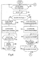
- FIG. 4 shows an operating block diagram of control unit 27. Operation commences with a standby block 100, which is exited when a given manual operation is performed, e.g. when the ignition key (not shown) of the electric vehicle (not shown) is set to a first angular position, and which is followed by a block 110 in which the main microprocessor (not shown) controlling control unit 27 is reset.
- a standby block 100 which is exited when a given manual operation is performed, e.g. when the ignition key (not shown) of the electric vehicle (not shown) is set to a first angular position, and which is followed by a block 110 in which the main microprocessor (not shown) controlling control unit 27 is reset.
- Block 110 is followed by a block 120, which determines the presence of alternating voltage at connector 55. In the event of a negative response (no voltage at connector 55), block 120 goes on to a block 130. Conversely (mains voltage at connector 55), block 120 goes on to a block 140, which loads the instructions permitting battery charge control of pairs of switches 33, 34, 35.
- Block 140 is followed by a block 150, which provides for opening switches 20a, 20b and 48a, 48b and closing switch 73 to form the circuit arrangement shown in Figure 3.
- Block 150 also provides for switching pairs of switches 33, 34, 35 as described above for the battery charge function, and is followed by a block 151 in which the above battery charge operations are performed.
- Block 151 is followed by a block 152, which determines whether direct voltage energy source 4 has been fully charged. In the event of a negative response, block 152 goes back to block 151. Conversely block 152 is followed by a block 153, which determines the absence of mains voltage at connector 55. In the event of a positive response (no mains voltage), block 153 goes back to block 100; conversely (mains voltage still present), energy source 4 is supplied with a weak current to maintain the charge.
- Block 130 loads the instructions permitting vehicle drive control of pairs of switches 33, 34, 35, and is followed by a block 160, which provides for closing switches 20a, 20b and 48a, 48b and opening switch 73 to form the circuit arrangement shown in Figure 2.
- Block 160 is followed by a block 170, which is exited when a manual operation is performed, e.g. when the ignition key (not shown) is set to a second angular position.
- Block 170 is followed by a block 180, which switches pairs of switches 33, 34, 35 as described for the vehicle drive function, to supply electric motor 8 to drive the vehicle.
- Block 180 is followed by a block 190, which awaits a motor-off signal. Upon said signal being received, motor 8 is turned off and block 190 goes back to block 100.
- Control unit 27 therefore provides for automatically charging the batteries when mains voltage is present at connector 55. Moreover, supply to electric motor 8 is disabled while charging the batteries.
Landscapes
- Engineering & Computer Science (AREA)
- Power Engineering (AREA)
- Transportation (AREA)
- Mechanical Engineering (AREA)
- Electric Propulsion And Braking For Vehicles (AREA)
- Charge And Discharge Circuits For Batteries Or The Like (AREA)
Description
- The present invention relates to a supply unit for an electric vehicle.
- As is known, an electric vehicle comprises a number of operating units, including a direct voltage energy source (normally comprising a number of batteries), an electric motor, and a supply unit for controlling energy supply from the energy source to the electric motor on the basis of a number of control signals; as well as various auxiliary units, e.g. for generating energy locally, recharging the direct voltage energy source, supplying electric equipment on the vehicle, etc.
- The various units of an electric vehicle are formed inside boxes, which are physically separate from one another and interconnected by electric power and signal cables extending between the boxes.
- Such a layout of the boxes poses various problems, including:
- bulk, due to the large number of boxes and the connecting lines between them;
- high cost of manufacturing a large number of separate units; and
- electromagnetic interference, due to the presence of a large number of electric power cables.
-
- Documents WO93/01650 and EP-116.925 describe charging devices for electically propelled vehicles as described in the preamble of
claim 1. - It is an object of the present invention to improve integration of the various units of an electric vehicle, while at the same time reducing the number of units themselves. More specifically, it is an object of the present invention to provide a high degree of integration between the supply unit of an electric vehicle and the battery recharging unit, to form a single part-sharing unit for alternately supplying the electric motor and recharging the batteries.
- According to the present invention, there is provided a supply unit for an electric vehicle, as claimed in
Claim 1. - A non-limiting embodiment of the present invention will be described by way of example with reference to the accompanying drawings, in which:
- Figure 1 shows the electric circuit of a supply unit for an electric vehicle in accordance with the teachings of the present invention;
- Figure 2 shows the Figure 1 circuit in a first operating mode;
- Figure 3 shows the Figure 1 circuit in a second operating mode;
- Figure 4 shows an operating block diagram of a unit forming part of the Figure 1 circuit.
-
-
Number 1 in Figure 1 indicates a supply unit for an electric vehicle. -
Unit 1 comprises a rechargeable direct voltage energy source 4 (shown by the dotted line) for supplying - via a reconfigurable circuit 6 operating in a first supply mode - anelectric motor 8 for driving a vehicle (not shown).Unit 1 also comprises a device 10 connectable to an alternating voltage source (e.g. a 220 V, 50 Hz mains voltage) for supplying said voltage to reconfigurable circuit 6, which, when operating in a second battery-charge mode, rectifies the mains voltage to charge directvoltage energy source 4. - More specifically,
energy source 4 comprises a number of rechargeable batteries 13 (in the example shown, only two are indicated for the sake of simplicity) arranged in series, and which together supply a direct supply voltage V (e.g. of 240 V) between thepositive output terminal 15 and, respectively, thenegative output terminal 16 ofenergy source 4. Directvoltage energy source 4 also comprises at least onesafety fuse device 18 located in series withbatteries 13, and which is disconnected when the current supply from directvoltage energy source 4 exceeds the I2t (total square current) value of the fuse. -
Unit 1 also comprises afirst switching assembly 20 interposed between reconfigurable circuit 6 andoutputs voltage energy source 4, and comprising a pair ofswitches positive output terminal 15 and afirst line 22 of circuit 6, and betweennegative output terminal 16 and asecond line 23 of circuit 6.Switches drive device 25 controlled by acentral control unit 27 for opening/closing switching assembly 20 as described later on. -
Supply lines electronic switches electric motor 8. More specifically, each switch in eachpair respective line switches respective nodes electric lines electric motor 8, which, in the embodiment shown, is a three-phase motor. - Each pair of
switches electric line 22; and a "bottom" switch (indicated by the letter b) having a terminal connected to secondelectric line 23. - Each electronic switch may comprise a semiconductor device (in the example shown, an IGBT transistor) having a control terminal G supplied by
control unit 27 for opening/closing the electronic switch; and each electronic switch also comprises arecirculating diode 45 antiparallel with the semiconductor device. -
Supply lines respective switches second switching assembly 48, and which are activated synchronously by adrive device 50 controlled bycentral control unit 27. The portion ofelectric line 41 extending betweennode 37 andswitch 48a communicates with a first terminal of anelectric line 52 of device 10; theportion 43a ofelectric line 43 extending betweenswitch 48b andmotor 8 communicates with a first terminal of anelectric line 53 of device 10;electric lines charge connector 55 for connectingunit 1 to the mains voltage;line 52 is also provided with aswitch 57; and acapacitor 59 is interposed betweenlines - Reconfigurable circuit 6 also comprises a first
electrolytic filter capacitor 65 having a first terminal connected toline 23 and a second terminal connected to one terminal of a secondelectrolytic filter capacitor 66, the other terminal of which is connected toline 22.Electrolytic capacitors node 68 to which is connected afirst terminal 71a of a winding 71 having asecond terminal 71b connected tonode 39 via the interposition of athird switching assembly 73.Third switching assembly 73 comprises a single switch activated by adrive device 75 controlled bycontrol unit 27. Winding 71 forms the primary winding of atransformer 76 having asecondary winding 77, theoutput terminals negative output terminals negative output terminal 16 of directvoltage energy source 4 over anelectric line 81, andterminal 79a is connected to thepositive output terminal 15 of directvoltage energy source 4 over anelectric line 82 along which are provided, in series, aninductor 84 and afuse 85. - Finally, reconfigurable circuit 6 comprises a
capacitor 87 interposed betweenlines resistor 89 in parallel withcapacitor 87. - In actual use, when first, second and
third switching assemblies control unit 27 provides for a first operating mode ofunit 1, wherebyelectric motor 8 is supplied to drive the vehicle (not shown). To supply the electric motor, unit 27: - closes first switching assembly 20 (
switches - closes second switching assembly 48 (
switches - opens third switching assembly 73 (
switch 73 open). -
Switch 57 is also open, andconnector 55 is not connected to any voltage source. -
Unit 1 therefore assumes the circuit structure shown in Figure 2, which, for the sake of simplicity, only shows the Figure 1 circuit components supplied with voltage or in any way involved in supplyingelectric motor 8. - With reference to Figure 2, the positive and
negative terminals voltage energy source 4 are connected directly torespective lines switches switches voltage energy source 4. -
Unit 27 switches all the circuit 6 switches in known manner so thatelectric lines motor 8. The amplitude of alternating voltages Va, Vb, Vc is regulated as a consequence of manual adjustment of the speed and traveling direction of the electric vehicle (not shown).Capacitors lines motor 8 when the vehicle (not shown) is moving. - When
switching assemblies control unit 27 also provides for a second operating mode ofunit 1, whereby directvoltage energy source 4 is charged. To charge the direct voltage energy source, unit 27: - opens first switching assembly 20 (
switches - opens second switching assembly 48 (
switches - closes third switching assembly 73 (
switch 73 closed). -
Switch 57 is also closed, andconnector 55 is connected to an alternating mains voltage source R(ω) (220 V, 50 Hz). -
Unit 1 therefore assumes the circuit structure shown in Figure 3, which, for the sake of simplicity, only shows the Figure 1 circuit components supplied with voltage or in any way involved incharging batteries 13. - The mains voltage R(ω) at
connector 55 is supplied toelectric lines electric line 41 and theportion 43a ofelectric line 43 extending betweenswitch 48b (open) andelectric motor 8.Portion 43a ofelectric line 43 also communicates withelectric line 42 via an internal winding L (shown in the form of an inductor) ofelectric motor 8, so that the alternating mains voltage R(ω) atconnector 55 is applied tonodes nodes series switches Unit 27 therefore opens/closesswitches electric lines - Alternating mains voltage R(ω) is rectified using
switches electric motor 8 is connected betweenconnector 55 and the H active rectifying bridge to control the current harmonics in conformance with noise reduction regulations. - Voltage Vr between
lines capacitors - Now observe mesh M1 comprising switch 35a,
capacitor 66 and winding 71, and mesh M2 comprising switch 35b,capacitor 65 and winding 71. - If
switch 35a is closed (withswitch 35b open), winding 71 is supplied with a voltage Vl according to the equation:node 68 voltage = Vr - Vr/2 = Vr/2 - Conversely, if
switch 35b is closed (withswitch 35a open), winding 71 is supplied with a voltage Vl according to the equation:node 68 voltage = - Vr + Vr/2 = -Vr/2 - Consequently, when switches 35a and 35b are closed alternately (by control unit 27), winding 71 is supplied with an alternating voltage Vl oscillating between ±Vr/2. The alternating voltage ±Vr/2 supplied to the primary of transformer 76 (winding 71) is transferred to the secondary winding 77, the output voltage of which is supplied to the input of rectifying
bridge 79. Rectifyingbridge 79 therefore supplies a direct voltage Vc, which is supplied toterminals voltage energy source 4 to chargebatteries 13.Switches capacitors transformer 76 and rectifyingbridge 79, therefore form a direct-to-direct voltage converter for converting voltage Vr to an alternating voltage (Vl) which is supplied to a transformer and subsequently rectified. This therefore provides for static conversion, with galvanic type decoupling, of direct voltage Vr (betweenlines 22, 23) into a direct voltage Vc (supplied toterminals switches capacitors 65, 66) which are also used for supplyingelectric motor 8. Only a very small number of components (transformer 76 and diode bridge 79) are used solely for static conversion; andinductor 84 also provides for regulating the charge current ofbatteries 13. - The advantages of the present invention will be clear from the foregoing description.
Unit 1 in fact provides for a high degree of integration of the vehicle supply and battery charge units by forming a single part-sharing unit for alternately supplying the electric motor and charging the batteries. - In both the above operating modes,
unit 1 in fact shares the following components: - the semiconductor switches (pairs of
switches - the drive circuits (control unit 27);
- filter
capacitors - the windings of
electric motor 8. - Figure 4 shows an operating block diagram of
control unit 27. Operation commences with astandby block 100, which is exited when a given manual operation is performed, e.g. when the ignition key (not shown) of the electric vehicle (not shown) is set to a first angular position, and which is followed by ablock 110 in which the main microprocessor (not shown) controllingcontrol unit 27 is reset. -
Block 110 is followed by ablock 120, which determines the presence of alternating voltage atconnector 55. In the event of a negative response (no voltage at connector 55), block 120 goes on to ablock 130. Conversely (mains voltage at connector 55), block 120 goes on to ablock 140, which loads the instructions permitting battery charge control of pairs ofswitches Block 140 is followed by ablock 150, which provides for openingswitches switch 73 to form the circuit arrangement shown in Figure 3. Block 150 also provides for switching pairs ofswitches block 151 in which the above battery charge operations are performed.Block 151 is followed by ablock 152, which determines whether directvoltage energy source 4 has been fully charged. In the event of a negative response, block 152 goes back to block 151. Conversely block 152 is followed by ablock 153, which determines the absence of mains voltage atconnector 55. In the event of a positive response (no mains voltage), block 153 goes back to block 100; conversely (mains voltage still present),energy source 4 is supplied with a weak current to maintain the charge. - Block 130 loads the instructions permitting vehicle drive control of pairs of
switches block 160, which provides for closingswitches switch 73 to form the circuit arrangement shown in Figure 2.Block 160 is followed by ablock 170, which is exited when a manual operation is performed, e.g. when the ignition key (not shown) is set to a second angular position.Block 170 is followed by ablock 180, which switches pairs ofswitches electric motor 8 to drive the vehicle.Block 180 is followed by ablock 190, which awaits a motor-off signal. Upon said signal being received,motor 8 is turned off and block 190 goes back to block 100. -
Control unit 27 therefore provides for automatically charging the batteries when mains voltage is present atconnector 55. Moreover, supply toelectric motor 8 is disabled while charging the batteries. - Clearly, changes may be made to the supply unit as described and illustrated herein without, however, departing from the scope of the present invention as defined by the appended claims.
Claims (8)
- A supply unit for an electric vehicle, comprising:said electric circuit (6) being reconfigurable, and providing for a first operating mode to control the direct voltage supplied by the direct voltage energy source (4) and supply (Va, Vb, Vc) said electric motor (8); said reconfigurable electric circuit (6) also providing for a second operating mode alternative to said first operating mode and wherein an alternating voltage is supplied to said reconfigurable circuit (6); said reconfigurable circuit (6) forming, for said second operating mode, rectifying means (33a, 33b, 34a, 34b, 27) for rectifying said alternating voltage and forming at the output (79a, 79b) a rectified direct voltage (Vr) which is supplied to said battery (13) to charge (Vc) the battery,a direct voltage energy source (4) comprising at least one rechargeable battery (13);an electric motor (8) for driving said vehicle; andan electric circuit (6) interposed between outputs (15, 16) of said direct voltage energy source (4) and said electric motor (8);
said reconfigurable circuit comprising at least a first pair of first switches (33a, 33b) in series with each other and interposed between first and second electric lines (22, 23), a second pair of second switches (34a, 34b) in series with each other and interposed between said first and second lines (22, 23) and a third pair of third switches (35a, 35b) in series with each other and interposed between said first and second lines (22, 23)
the common terminals (37, 38) of said first, second and third switches defining first, second and third nodes (37, 38, 39) communicating with respective supply lines (41, 42, 43) for supplying said electric motor (8),
characterized by comprising direct-direct transforming means interposable between an output of said rectifying means (33a, 33b, 34a, 34b, 27) and said outputs of said direct voltage energy source (4); said direct-direct transforming means providing for galvanic type decoupling of said rectifying means and said direct voltage energy source (4), and for picking up said rectified direct voltage (Vr) to form at the output a direct charging voltage (Vc) applied to said outputs (15, 16) of said direct voltage energy source (4); said direct-direct transforming means being enabled for said second operating mode, and being disabled for said first operating mode. - A supply unit as claimed in claim 1, wherein said direct-direct transforming means comprises:capacitor means (65, 66) which are charged with said rectified direct voltage (Vr);said third switches (35a, 35b) that are disposed connectable (73) to said capacitor means (65, 66), and which are switched to generate an alternating signal (Vl) using the direct voltage present at the capacitor means (65, 66);decoupling transforming means (76) having a primary winding (71) to which said alternating signal (v) is applied; andfinal rectifying means (79) interposed between a secondary winding (77) of said decoupling transforming means (76) and said direct voltage energy source (4).
- A unit as claimed in Claim 2, wherein said direct-direct transforming means comprise first cutout switching means (73) settable to a first operating position corresponding to said first operating mode, so that said capacitor means (65, 66) are disconnected from said third switches (35a, 35b);
said first cutout switching means (73) also being settable to a second operating position corresponding to said second operating mode, to connect said capacitor means (65, 66) to said third switches (35a, 35b) via said primary winding (71). - A unit as claimed in Claim 2 or 3, wherein said first and second capacitor means (65, 66) in are disposed in series with each other and interposed between said first and second line (22, 23) so that each is charged with part of said rectified direct voltage (Vr) present between said first (22) and second (23) line;
said primary winding being interposed between a node (39) at which said third switches (35a, 35b) communicate, and a node at which said first and second capacitor means (65, 66) communicate;
in said second operating mode, said third switches (35a, 35b) being switched alternately to generate said alternating signal (Vl) applied to said primary winding (71). - A unit as claimed in any one of the foregoing claims, wherein said reconfigurable circuit comprises first switching means (48) settable to a first position corresponding to the first operating mode, so that said supply lines (41, 42) communicate with said electric motor to supply said alternating supply voltage;
said first switching means (48) being settable to a second position corresponding to the second operating mode, so that said electric motor is at least partly disconnected from said supply lines (41, 42) and said alternating voltage is supplied to said first and second nodes (37, 38); in said second operating mode, said first (33a, 33b) and second (34a, 34b) switches being activated in a second switching mode, so that said rectified direct voltage (Vr) is present on said first and second lines (22, 23). - A unit as claimed in Claim 5, wherein in said second position, said first switching means (48) interpose inductor means, forming part of said electric motor, between one (38) of said nodes and a source of said alternating voltage
- A unit as claimed in claim 3, wherein second cutout switching means (20) are interposed between said outputs (15, 16) of said direct voltage energy source (4) and said first and second line (22, 23); said second cutout switching means (20) being closed in said first operating mode to permit energy flow from said direct voltage energy source (4) to said motor (8), and being open in said second operating mode. to disconnect said first and second line (22, 23) from said direct voltage energy source (4).
- A unit as claimed in any one of the foregoing Claims, wherein are provided electronic control means (27) for determining (120) the presence of said alternating voltage so as to automatically enable (140, 150) said second operating mode and disable said first operating mode.
Priority Applications (3)
| Application Number | Priority Date | Filing Date | Title |
|---|---|---|---|
| DE69630231T DE69630231T2 (en) | 1996-12-19 | 1996-12-19 | Supply unit for an electric vehicle |
| EP96830637A EP0849111B1 (en) | 1996-12-19 | 1996-12-19 | Supply unit for an electric vehicle |
| US08/993,906 US5875106A (en) | 1996-12-19 | 1997-12-18 | Galvanic decoupling supply unit for an electric vehicle |
Applications Claiming Priority (1)
| Application Number | Priority Date | Filing Date | Title |
|---|---|---|---|
| EP96830637A EP0849111B1 (en) | 1996-12-19 | 1996-12-19 | Supply unit for an electric vehicle |
Publications (2)
| Publication Number | Publication Date |
|---|---|
| EP0849111A1 EP0849111A1 (en) | 1998-06-24 |
| EP0849111B1 true EP0849111B1 (en) | 2003-10-01 |
Family
ID=8226082
Family Applications (1)
| Application Number | Title | Priority Date | Filing Date |
|---|---|---|---|
| EP96830637A Expired - Lifetime EP0849111B1 (en) | 1996-12-19 | 1996-12-19 | Supply unit for an electric vehicle |
Country Status (3)
| Country | Link |
|---|---|
| US (1) | US5875106A (en) |
| EP (1) | EP0849111B1 (en) |
| DE (1) | DE69630231T2 (en) |
Families Citing this family (15)
| Publication number | Priority date | Publication date | Assignee | Title |
|---|---|---|---|---|
| DE10059331A1 (en) * | 2000-11-29 | 2002-06-13 | Siemens Ag | Reduction of system vibrations in an electric motor operated on a converter with a voltage intermediate circuit by periodically decoupling the intermediate circuit from the mains and corresponding voltage intermediate circuit converter |
| US7012822B2 (en) * | 2002-02-20 | 2006-03-14 | Ballard Power Systems Corporation | Integrated traction inverter module and DC/DC converter |
| US7426416B2 (en) * | 2004-10-20 | 2008-09-16 | International Business Machines Corporation | System and method for sensor replication for ensemble averaging in micro-electromechanical systems (MEMS) |
| DE102006001764A1 (en) * | 2005-09-21 | 2007-03-29 | Temic Automotive Electric Motors Gmbh | Safety device for motor vehicles |
| KR100999969B1 (en) * | 2007-12-12 | 2010-12-09 | 현대자동차주식회사 | Apparatus for charging battery |
| FR2946473B1 (en) * | 2009-06-09 | 2011-08-19 | Renault Sas | RECHARGEABLE ELECTROMOTING ASSEMBLY FROM AN ELECTRICAL NETWORK, AND DEDICATED CONNECTION HOUSING. |
| EP2263906A1 (en) * | 2009-06-18 | 2010-12-22 | Siemens Aktiengesellschaft | Method for operating a vehicle |
| EP2539987B1 (en) * | 2010-02-23 | 2013-11-20 | ABB Research Ltd. | An electric plant with capacity to charge electric batteries |
| JP5736768B2 (en) * | 2010-12-24 | 2015-06-17 | 株式会社豊田中央研究所 | Battery charger |
| US9425705B2 (en) * | 2012-08-13 | 2016-08-23 | Rockwell Automation Technologies, Inc. | Method and apparatus for bypassing cascaded H-bridge (CHB) power cells and power sub cell for multilevel inverter |
| WO2017041144A1 (en) | 2015-09-11 | 2017-03-16 | Invertedpower Pty Ltd | A controller for an inductive load having one or more inductive windings |
| US11479139B2 (en) | 2015-09-11 | 2022-10-25 | Invertedpower Pty Ltd | Methods and systems for an integrated charging system for an electric vehicle |
| US11267358B2 (en) | 2017-05-08 | 2022-03-08 | Invertedpower Pty Ltd | Vehicle charging station |
| JP6582327B2 (en) * | 2017-05-31 | 2019-10-02 | 本田技研工業株式会社 | Electric vehicle |
| US11342878B1 (en) | 2021-04-09 | 2022-05-24 | Rockwell Automation Technologies, Inc. | Regenerative medium voltage drive (Cascaded H Bridge) with reduced number of sensors |
Family Cites Families (6)
| Publication number | Priority date | Publication date | Assignee | Title |
|---|---|---|---|---|
| US4136382A (en) * | 1978-01-18 | 1979-01-23 | Exxon Research & Engineering Co. | Converter system |
| DE3305224A1 (en) * | 1983-02-16 | 1984-08-16 | Bbc Brown Boveri & Cie | ON-BOARD BATTERY CHARGER |
| US4920475A (en) * | 1988-03-07 | 1990-04-24 | California Institute Of Technology | Integrated traction inverter and battery charger apparatus |
| DE4107391A1 (en) * | 1991-03-08 | 1992-09-10 | Abb Patent Gmbh | Electric road vehicle with rechargeable battery - has DC=AC converter acting as DC regulator during battery recharging |
| WO1993001650A1 (en) * | 1991-07-08 | 1993-01-21 | Siemens Aktiengesellschaft | Process and device for operating as on-board charging set the inverse rectifier of the threephase current drive of an electric car |
| US5291388A (en) * | 1992-04-16 | 1994-03-01 | Westinghouse Electric Corp. | Reconfigurable inverter apparatus for battery-powered vehicle drive |
-
1996
- 1996-12-19 DE DE69630231T patent/DE69630231T2/en not_active Expired - Fee Related
- 1996-12-19 EP EP96830637A patent/EP0849111B1/en not_active Expired - Lifetime
-
1997
- 1997-12-18 US US08/993,906 patent/US5875106A/en not_active Expired - Fee Related
Also Published As
| Publication number | Publication date |
|---|---|
| EP0849111A1 (en) | 1998-06-24 |
| US5875106A (en) | 1999-02-23 |
| DE69630231D1 (en) | 2003-11-06 |
| DE69630231T2 (en) | 2004-08-05 |
Similar Documents
| Publication | Publication Date | Title |
|---|---|---|
| EP0849111B1 (en) | Supply unit for an electric vehicle | |
| EP3992019A1 (en) | Vehicle and energy conversion device and power system thereof | |
| US5440179A (en) | UPS with bi-directional power flow | |
| EP0843822B1 (en) | A bidirectional load and source cycler | |
| US7800346B2 (en) | Device and method for equalizing charges of series-connected energy stores | |
| CN111052532B (en) | Method and device for charging an energy store | |
| CN110289669B (en) | AC charging of intelligent battery | |
| US5347164A (en) | Uninterruptible power supply having a 115V or 230V selectable AC output and power saving | |
| US5253157A (en) | Half-bridge inverter with capacitive voltage equalizer | |
| EP0984543B1 (en) | Electrical system for motor vehicles | |
| US5717303A (en) | DC motor drive assembly including integrated charger/controller/regenerator circuit | |
| US9487095B2 (en) | Charging and discharging device | |
| WO1992002076A1 (en) | Power supply for single phase boost | |
| KR20150073291A (en) | Power conversion device | |
| KR20120000527A (en) | Device for charging accumulator means | |
| EP0782209A1 (en) | A supply system with fuel cells and a buffer battery for a self-supplied vehicle with electric drive | |
| KR20210018598A (en) | Electric power conversion system and control method therefor | |
| EP1083646A2 (en) | Storage module | |
| KR102586729B1 (en) | Charging circuit for vehicle-side electrical energy storage | |
| US6369548B1 (en) | Voltage switch-over device | |
| GB2050089A (en) | Traction equipment | |
| WO1988006814A1 (en) | IMPROVEMENTS IN OR RELATING TO D.C. to A.C. INVERTERS | |
| US5013991A (en) | Multi-voltage alternator with integral bank switched bridge | |
| JPH0833233A (en) | Ac/dc uninterruptible power supply | |
| US4170748A (en) | Circuit arrangement for electrically driven motor vehicles |
Legal Events
| Date | Code | Title | Description |
|---|---|---|---|
| PUAI | Public reference made under article 153(3) epc to a published international application that has entered the european phase |
Free format text: ORIGINAL CODE: 0009012 |
|
| AK | Designated contracting states |
Kind code of ref document: A1 Designated state(s): DE FR GB IT |
|
| AX | Request for extension of the european patent |
Free format text: AL;LT;LV;RO;SI |
|
| 17P | Request for examination filed |
Effective date: 19981207 |
|
| AKX | Designation fees paid |
Free format text: DE FR GB IT |
|
| RBV | Designated contracting states (corrected) |
Designated state(s): DE FR GB IT |
|
| RAP1 | Party data changed (applicant data changed or rights of an application transferred) |
Owner name: ANSALDO RICERCHE S.R.L. |
|
| 17Q | First examination report despatched |
Effective date: 20010315 |
|
| GRAH | Despatch of communication of intention to grant a patent |
Free format text: ORIGINAL CODE: EPIDOS IGRA |
|
| GRAH | Despatch of communication of intention to grant a patent |
Free format text: ORIGINAL CODE: EPIDOS IGRA |
|
| GRAA | (expected) grant |
Free format text: ORIGINAL CODE: 0009210 |
|
| AK | Designated contracting states |
Kind code of ref document: B1 Designated state(s): DE FR GB IT |
|
| REG | Reference to a national code |
Ref country code: GB Ref legal event code: FG4D |
|
| REF | Corresponds to: |
Ref document number: 69630231 Country of ref document: DE Date of ref document: 20031106 Kind code of ref document: P |
|
| ET | Fr: translation filed | ||
| PLBE | No opposition filed within time limit |
Free format text: ORIGINAL CODE: 0009261 |
|
| STAA | Information on the status of an ep patent application or granted ep patent |
Free format text: STATUS: NO OPPOSITION FILED WITHIN TIME LIMIT |
|
| 26N | No opposition filed |
Effective date: 20040702 |
|
| PGFP | Annual fee paid to national office [announced via postgrant information from national office to epo] |
Ref country code: FR Payment date: 20051222 Year of fee payment: 10 |
|
| PGFP | Annual fee paid to national office [announced via postgrant information from national office to epo] |
Ref country code: GB Payment date: 20051228 Year of fee payment: 10 |
|
| PGFP | Annual fee paid to national office [announced via postgrant information from national office to epo] |
Ref country code: DE Payment date: 20060125 Year of fee payment: 10 |
|
| PG25 | Lapsed in a contracting state [announced via postgrant information from national office to epo] |
Ref country code: DE Free format text: LAPSE BECAUSE OF NON-PAYMENT OF DUE FEES Effective date: 20070703 |
|
| GBPC | Gb: european patent ceased through non-payment of renewal fee |
Effective date: 20061219 |
|
| REG | Reference to a national code |
Ref country code: FR Ref legal event code: ST Effective date: 20070831 |
|
| PG25 | Lapsed in a contracting state [announced via postgrant information from national office to epo] |
Ref country code: GB Free format text: LAPSE BECAUSE OF NON-PAYMENT OF DUE FEES Effective date: 20061219 |
|
| PG25 | Lapsed in a contracting state [announced via postgrant information from national office to epo] |
Ref country code: FR Free format text: LAPSE BECAUSE OF NON-PAYMENT OF DUE FEES Effective date: 20070102 |
|
| PGFP | Annual fee paid to national office [announced via postgrant information from national office to epo] |
Ref country code: IT Payment date: 20071228 Year of fee payment: 12 |
|
| PG25 | Lapsed in a contracting state [announced via postgrant information from national office to epo] |
Ref country code: IT Free format text: LAPSE BECAUSE OF NON-PAYMENT OF DUE FEES Effective date: 20081219 |