EP0848784B1 - Wiederverwenbarer, expandierbarer überbrüchungsstopfen - Google Patents
Wiederverwenbarer, expandierbarer überbrüchungsstopfen Download PDFInfo
- Publication number
- EP0848784B1 EP0848784B1 EP96930448A EP96930448A EP0848784B1 EP 0848784 B1 EP0848784 B1 EP 0848784B1 EP 96930448 A EP96930448 A EP 96930448A EP 96930448 A EP96930448 A EP 96930448A EP 0848784 B1 EP0848784 B1 EP 0848784B1
- Authority
- EP
- European Patent Office
- Prior art keywords
- bridge plug
- packing
- slip segments
- packing element
- packing member
- Prior art date
- Legal status (The legal status is an assumption and is not a legal conclusion. Google has not performed a legal analysis and makes no representation as to the accuracy of the status listed.)
- Expired - Lifetime
Links
Images


Classifications
-
- E—FIXED CONSTRUCTIONS
- E21—EARTH OR ROCK DRILLING; MINING
- E21B—EARTH OR ROCK DRILLING; OBTAINING OIL, GAS, WATER, SOLUBLE OR MELTABLE MATERIALS OR A SLURRY OF MINERALS FROM WELLS
- E21B33/00—Sealing or packing boreholes or wells
- E21B33/10—Sealing or packing boreholes or wells in the borehole
- E21B33/12—Packers; Plugs
- E21B33/1208—Packers; Plugs characterised by the construction of the sealing or packing means
-
- E—FIXED CONSTRUCTIONS
- E21—EARTH OR ROCK DRILLING; MINING
- E21B—EARTH OR ROCK DRILLING; OBTAINING OIL, GAS, WATER, SOLUBLE OR MELTABLE MATERIALS OR A SLURRY OF MINERALS FROM WELLS
- E21B33/00—Sealing or packing boreholes or wells
- E21B33/10—Sealing or packing boreholes or wells in the borehole
- E21B33/12—Packers; Plugs
- E21B33/129—Packers; Plugs with mechanical slips for hooking into the casing
Definitions
- the invention concerns a retrievable bridge plug according to the introductory part of Claim 1.
- a bridge plug can be used to isolate against changes in pressure in both directions.
- Such bridge plugs comprises in principle a sealing part for sealing the differential pressure, and an anchoring part for preventing movement of the bridge plug due to the pressure force.
- the bridge plug will in many circumstances have to pass constrictions, for example valves and nipples (hereafter called "restrictions”), after which it becomes located in a wider casing diameter.
- known retrievable bridge plugs Due to their constructions, known retrievable bridge plugs have a limitation in the expansion, which prevents use of bridge plugs in some oil and gas wells.
- bridge plugs exist in many dimensions, adapted to the different casing dimensions where the plug is to be placed. This follows from the fact that conventional bridge plugs have a comparatively low expansion rate.
- the low expansion rate of conventional bridge plugs is partly due to the construction of the anchoring part, and partly due to the structure of the packing element.
- a common method for anchoring plugs has been to use conical slip segments which are forced out radially, between two conical pipes which are forced together axially. In this method, the expansion of the slip segments is limited by the outer diameter of the conical pipes. Without active pulling of the slip segments, they can become stuck in restrictions when being pulled out of the oil or gas well.
- the packing element expands when a rubber body is squeezed axially.
- expandable bridge plugs include those according to DE-C-3108475, FR-A-2085893 and US-A-2963091.
- DE-C-3108475 discloses a packing element for a bridge plug.
- the axially compressible packing element comprises a central packing ring having two oblique side walls, a first plurality of frustoconical packing rings arranged adjacent one side of the central packing ring, and a second plurality of frustoconical packing rings arranged adjacent the other side of the central packing ring.
- the radial angle of their oblique side walls is larger than that of the side walls of the central packing ring.
- the external diameter of all frustoconical packing rings will increase in response to axial compression.
- this expansion of the entire packing element is limited due to the particular structure of the element.
- FR-A-2085893 (corresponding to US-A-3,645,334) concerns a retrievable well packer apparatus having a mandrel movable between extended and contracted positions within an anchor body that carries normally retracted slips. In operation, the slips may be brought into engagement with the walls of the well casing to anchor the apparatus against movement in either direction in the well.
- a compression sleeve carries a plurality of annular elastic packing elements that may be compressed and expanded into sealing engagement with the well casing. Also in this case, only a limited expansion of the elastic packing elements is possible.
- US-A-2963091 discloses a packer apparatus for isolating separate producing zones in a well bore.
- the apparatus includes axially separated elastic packing sleeves that may be expanded to seal against the well casing, as well as axially separated slips that may be brought into anchoring engagement with the well casing.
- Each packing sleeve is a single elastic element that can be only slightly expanded.
- Fig. 1 shows a bridge plug 1 according to the invention, before setting in the casing.
- the bridge plug 1 is comprised of the main elements packing element 2, anchoring means 3, equalizing valve 4, finger connection 5 and locking means 6.
- the bridge plug 1 is arranged to be brought into and anchored in for example, a casing 7.
- the bridge plug 1 comprise a tubular outer sleeve 8, forming the outer delimitation of the bridge plug.
- In the back end of the bridge plug (to the left of Fig. 1), there is provided within the outer sleeve 8 a tubular downhaul tube 9 with an outer diameter that is somewhat smaller then the inner diameter of the outer sleeve 8, so that a gap is formed therebetween.
- the downhaul tube 9 forms a section 11, having an external diameter corresponding to the inner diameter of the outer sleeve 8.
- an inward flange 12 This flange enganges an outward flange 15, forming the end of a section 14 of a tubular package mandrel 13.
- the flange 15 and the section 14 are split axially, so that radial movement is possible.
- Inside the flange 15 is a further flange 17, forming the end of a cut-off tube 16.
- the flange 17 has further a section 37 supporting the end of the flange 15.
- the sections 11 and 14 with their flanges 12 and 15 together form the finger connection 5, preventing cut-off by means of the support from the section 37 of the flange 17.
- Fig. 2 shows the bridge plug 1 during insertion in the casing.
- Outer sleeve 8 is moved relative to the downhaul tube 9, the cut-off tube 16 and the package mandrel 13, by means of a suitable running tool (not shown).
- the running tool excerts a force F1 between the outer sleeve 8 and the package mandrel 13. This involes the slip segments 22 of the anchoring means 3 being expanded and forced onto the casing wall. This will be further explained below. Movement of the outer sleeve 8 will continue even though the attached anchoring means will lead to the packing element 2 being squeezed axially, so that it expands out against the tube.
- the section 10 will hook up with outer sleeve 8, which will then draw the packing element 2 down while the anchoring means 3 holds the bridge plug 1 relative to the casing wall 7.
- the anchoring means 3 will be released from the casing wall 7.
- the bridge plug 1 is then loose and can be drawn out of the cased well.
- the weight of the released part of the plug will draw the packing element to its original diameter.
- Return springs 27 as shown in Fig. 9 and the weight of the released part of the plug provide the slip segments 22 to be drawn in to the anchoring means.
- the bridge plug is then loose and can be drawn out of the cased well.
- the plug When pulling the plug out of, for example, an oil or gas well, the plug will meet restrictions on its way out of the well. If the package element, due to permanent deformation, has a greater diameter than a restriction, the plug can still be drawn through the restriction, because the reinforcement prevents the elastomer to become stuck in the cased well.
- the anchoring means is also formed so that the slip segments are drawn into the plug if the slip segments hit a restriction. However, this can only occur if the slip segments do not go down by means of the return springs and the weight of the released part of the plug (see description of the anchoring means).
- the equalizing valve 4 is situated within the tubular package mandrel 13.
- the equalizing valve 4 can be used for two purposes. When the bridge plug is to be drawn out, it is desirable to equalize the pressure on both sides of the packing element 2. This is done by the dedicated strut of the retrieval tool (not shown) being thrust into the circulation port 4, so that communication for fluid and pressure occurs between both sides of the packing element 2. Furthermore, if it is desired to circulate fluid through the bridge plug while it is set, it can be done by opening the circualtion port 4 with a dedicated opening tool (not shown).
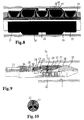
- the packing element 2 is constructed from a number of supporting packing members 31, 32, 33 and a number of sealing packing members 34, 35 (Fig. 8).
- the different packing members are separate parts that can be mounted so that they together form a packing element.
- Each sealing packing member is isolated so that fluid and pressure in the cased well can not pass beyond this point after the sealing packing member is expanded against the casing wall 7.
- the function of the supporting packing members is to prevent undesired movement of the sealing packing member during pressure influence, by minimizing the gap through which the sealing packing member can expand. Since the object of the supporting packing members 31, 32, 33 is merely to reduce the gap between the bridge plug 1 and the casing 7, so that the sealing packing members 34, 35 are stable during pressure influence, also other types of expandable supports than reinforced elastomers may be used, such as steel lamellae, which are expanded by conical clamps 39, and held in place with a radial force against the center, through reinforcement threads 40.
- the packing element can be constructed in a number of ways. Generally, this can be expressed so that by a combination of low pressure and small gap, the packing element is constructed from only one sealing packing member and no supporting packing members. With high pressure and large gap, one or more supporting packing members are used to give the necessary support to the sealing packing member, so that extrusion of the sealing packing member during some time, does not lead to leakage.
- Fig. 6 is shown an embodiment comprising a sealing packing member 34 and two support packing members 31, 32.
- FIG. 7 is shown an embodiment with two support packing members 31, 31'; 32, 32', having different diameters on each side of the sealing packing member 34, where the support packing members 31, 32 nearest the clamp give support to the support packing member 31', 32', nearest the sealing packing member 34.
- fig. 8 is shown the prefered embodiment having two sealing packing members 34, 35 and three support packing members 31, 32, 33, where each support packing member will seal against fluid and pressure from each side. This prevents the sealing packing member to acquire an undesired deformation when the differential pressure rises and falls, respectively, on one of the sides relative to the other side.
- the packing members comprise an inner core 38 of a resilient material (e.g. rubber) located between two conical clamps 39.
- An expandable reinforcement bag 40 is situated over the core 38, and is attached to the clamps. Over the reinforccement, an outer layer 41 of the same material as the core 38 is moulded to the reinforcement bag 40 and the core 38 (Fig. 6). At expansion, the reinforcement approaches self locking (blocking) at a predetermined diameter and compression length. The reinforcement of the packing members will function as a ductile container during expansion.
- the reinforcement is wound in different angles over the supporting packing member and sealing packing member.
- Two cord layers 40a, 40b; 40a', 40b' are provided, over both supporting packing member 31 and sealing packing member 34.
- the compression length is given by the packing member clamps which approach each other. This implies that the packing members are not displaced at axial load, and an axial force F1 can be transferred directly through the packing member via the clamps, without the elastomer and reinforcement become overloaded.
- the axial force F1 can thus be used to position the slip segments out against the casing wall with a desired radial force.
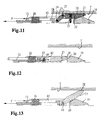
- a rear inclined surface 20 against which an anchoring pad 22 may slide on an inclined surface 21 In a front section 19 of the bridge plug 1 is provided a rear inclined surface 20 against which an anchoring pad 22 may slide on an inclined surface 21.
- a number of slip segments 22 are situated around the circumference of the bridge plug 1. In the preferred embodiment of present invention there are three slip segments 22, but it will be understood that a different number also can be used.
- the slip segments 22 are preferably provided with a friction surface 28 which can be pressed out against and onto the casing 7.
- the slip segments 22 are, at their rear, connected to a pivotable joint 23 by a first pin 25.
- the opposite ends of the joints 23 are connected to a displacement tube 26 by a second pin 24.
- the front section 19 with rear inclined surface 20 is connected with a package mandrel 13 via a through connection 36.
- the slip segments 22 are anchored against the center of the bridge plug 1 by return springs 27. This implies that the slip segments are in their rest position, and the bridge plug 1 can be freely inserted in and withdrawn from the casing 7.
- Fig. 10 shows a section taken along the line X-X in Fig. 9, illustrating the springs 27 in the slip segments 22.
- the anchoring means 3 is shown in activated condition, with the slip segments 22 pressed against the casing wall 7.
- the slip segments 22 will be pressed out against the casing wall 7. This outwardly acting force will also counteract the force from the return springs 27.
- the slip segments 22 will move along the inclined surfaces 20, 21 until the leading edge of the anchorings pads 22 contact against the casing wall.
- the rear edge of the anchoring pad 22 Upon further movement of the displacement tube 26, the rear edge of the anchoring pad 22 will be moved out via joints 23, so that all of the friction surface 28 is pressed in against tube wall 7.
- Pulling of the bridge plug 1 is done by withdrawing the displacement tube 26 with a force that is substantially less then the running force F1. This is so because if the support under the inclined surface 21 of the anchoring pad 22 disappears, it will immediately lead to the loosening of the slip segments 22 form the casing wall. Simultanously, the pivotable joint 23 in the rear edge of the anchoring pad will rotate around the pin 24 when the displacement tube 26 is drawn up. This kind of rotation in the joint 23 leads to a radial force against the center of the plug at the rear end of the anchoring pad 22 by the pin 25. Upon a further drawing of the displacement tube 26, the joint 23 will hit an edge 43, which will result in a downward force on the anchoring pad 22. The force of the return springs 27 will also help in drawing the slip segments.
- the inclined surface 21 of the slip segments 22, the inclined surface 20 of the bridge plug 1 and the joints 23 limit the expansion of the slip segments.
- the slip segments 22 are attached only by one pin 44 and loaded with a return spring 42.
- the length of the stroke can be increased, and a greater expansion rate is achieved.
- Fig. 13 shows the anchoring means 3 from Fig. 12 in expanded state, with the friction surface 28 pressed out against the casing wall 7.
- Drawing of the anchorings pads 22 is done in the same way as the preferred embodiment, by pulling the displacement tube out relative to the leading edge of the plug. This will lead to the contact between the inclined surfaces 20, 21 disappearing, whereafter the slip segments 22 will hit the edge 43 that lies over the pivoting point 44. The slip segments 22 are thus forced in against the center of the plug 1.
- the return spring 42 can be situated in the rear edge of the slip segments 22, as shown in Fig. 12, so that the slip segments 22 get an active rotation in against the center of the plug.
Landscapes
- Geology (AREA)
- Life Sciences & Earth Sciences (AREA)
- Engineering & Computer Science (AREA)
- Mining & Mineral Resources (AREA)
- Environmental & Geological Engineering (AREA)
- Fluid Mechanics (AREA)
- Physics & Mathematics (AREA)
- General Life Sciences & Earth Sciences (AREA)
- Geochemistry & Mineralogy (AREA)
- Earth Drilling (AREA)
- Pressure Vessels And Lids Thereof (AREA)
- Bridges Or Land Bridges (AREA)
- Taps Or Cocks (AREA)
- Manufacture Of Porous Articles, And Recovery And Treatment Of Waste Products (AREA)
Claims (11)
- Brückenstopfen (1) zur Verwendung in einer Verrohrung (7) beispielsweise in Ölund/oder Gasbohrungen mit einem Packerelement (2) aus einem elastischen Material, worin das Packerelement (2) so ausgebildet ist, das es sich bei Stoß von einem Laufwerkzeug von einem ersten Durchmesser ausdehnt zu einem Durchmesser, der größer als der erste Durchmesser ist und dem Innendurchmesser der abzudichtenden Verrohrung entspricht, und worin der Brückenstopfen (1) außerdem ein Verankerungsmittel (3) aufweist, das vorgesehen ist, um den Brückenstopfen (1) in der Verrohrung durch eine Reibungsfläche (28) an Ort und Stelle zu halten, die radial nach außen gegen die Verrohrung (7) gepreßt wird, dadurch gekennzeichnet, daß das Packerelement (2) in Zonen unterteilt ist, die wenigstens ein ausdehnbares abdichtendes Packerglied (34, 35) und wenigstens ein ausdehnbares stützendes Packerglied (31, 32, 33) bilden, wobei jedes stützende Packerglied (31, 32, 33) so ausgebildet ist, daß es sich bis zu einem kleineren Durchmesser als ein abdichtendes Packerglied (34, 35) ausdehnt.
- Brückenstopfen nach Anspruch 1, dadurch gekennzeichnet, daß das Packerelement (2) einen inneren Kern (38) aufweist, der aus einem elastischen Material, wie Gummi, hergestellt ist, das zwischen zwei konischen Packergliedklauen (39) angeordnet ist und worin ein Verstärkungscord (40) über den inneren Kern (38) gewickelt und mit den Klauen (39) verbunden ist und wobei über der Verstärkung eine Außenschicht (41) vorgesehen ist, die an die Verstärkung (40) und den Kern (38) angeformt ist.
- Brückenstopfen nach Anspruch 1 bis 2, dadurch gekennzeichnet, daß die konischen Packergliedklauen (39) so angeordnet sind, daß sie sich gegeneinander bewegen, so daß ein Druck durch eine axiale Kraft durch das Packerelement (2) über die Klauen (39) übertragen wird, ohne daß das Elastomer und die Verstärkung (40) überlastet werden.
- Brückenstopfen nach Anspruch 1 bis 3, dadurch gekennzeichnet, daß der Verstärkungscord (40) im Packerelement (2) aus zwei oder mehr Lagen besteht, wobei der Winkel zwischen den Lagen und die Kompressionslänge so ist, daß jedes stützende Packerglied (31, 32, 33) und jedes abdichtende Packerglied (34, 35) bei einem gewünschten Durchmesser stabilisiert sind.
- Brückenstopfen nach Anspruch 1 bis 4 , dadurch gekennzeichnet, daß der Verstärkungscord (40) dafür vorgesehen ist, daß er beim Ziehen des Stopfens durch ein spezielles Rückholwerkzeug das Packerelement (2) gegen die Mitte des Stopfens (1) nach innen zieht, während der Verstärkungscord (40) nahe der Klaue (39) axial gedehnt wird.
- Brückenstopfen nach Anspruch 1 bis 5, dadurch gekennzeichnet, daß jedes stützende Packerglied (31, 32, 33) getrennt von jedem abdichtenden Packerglied (34, 35) in Form eines Gummielements oder expandierbarer Stahllamellen und/oder eines Kunststoffelements ausgebildet ist.
- Brückenstopfen nach Anspruch 1 bis 6, dadurch gekennzeichnet, daß das Verankerungsmittel aus wenigstens zwei Klappsegmenten (22) mit einer Reibungsfläche (28) besteht, welche dafür vorgesehen ist, daß sie nach außen gegen und vorzugsweise in die Verrohrung (7) gepreßt wird, wobei eine innere schräge Führungsfläche (21) an den Klappsegmenten (22) so ausgebildet ist, daß sie längs einer äußeren schrägen Fläche (20) nahe der Kopfkante des Brückenstopfens (1) gleitet.
- Brückenstopfen nach Anspruch 7, dadurch gekennzeichnet, daß jedes der Klappsegmente (22) an seiner hinteren Kante durch einen ersten Stift (25) mit einem schwenkbaren Gelenk (23) verbunden ist und daß die Gelenke (23) an den entgegengesetzten Enden durch einen zweiten Stift (24) mit einem Verschiebungsrohr (26) verbunden sind, wobei die Klappsegmente (22) so angeordnet sind, daß sie die Verrohrung (7) zuerst mit einem Kopfteil der Reibungsfläche (28) berühren und anschließend sich auch mit der Hinterkante nach außen bewegen, wenn das Verschiebungsrohr (26) weiter in Richtung auf die Kopfkante des Brückenstopfens (1) bewegt wird.
- Brückenstopfen nach Anspruch 8, dadurch gekennzeichnet, daß die Klappsegmente (22) über das schwenkbare Gelenk (23) aktiv nach unten gegen die Mitte des Stopfens gezogen werden, wenn das Verschiebungsrohr (26) in Richtung auf die Hinterkante des Brückenstopfens (1) bewegt wird, so daß das Gelenk (23) auf eine Kante (43) trifft.
- Brückenstopfen nach Anspruch 7 bis 9, dadurch gekennzeichnet, daß die Klappsegmente (22) durch wenigstens eine Rückholfeder (27, 44) zur Mitte des Brückenstopfens (1) hin beaufschlagt und dort verankert sind.
- Brückenstopfen nach einem der vorangehenden Ansprüche, dadurch gekennzeichnet, daß ein Packungsdorn (13) mit einer Durchlaßöffnung (4), die über eine Durchgangsverbindung (36) mit einem Frontabschnitt (19) verbunden ist, so ausgebildet ist, daß er mittels einer Fingerverbindung (5) vom Rest des Brückenstopfens (1) beim Ziehen desselben freikommt, so daß das Gewicht der freigegebenen Elemente (13, 4, 19, 36) dazu beiträgt, das Packerelement (2) herein zu ziehen und die Klappsegmente (22) zur Mitte des Stopfens (1) herein zu ziehen.
Applications Claiming Priority (3)
| Application Number | Priority Date | Filing Date | Title |
|---|---|---|---|
| NO953546 | 1995-09-08 | ||
| NO953546A NO301945B1 (no) | 1995-09-08 | 1995-09-08 | Ekspanderende opphentbar broplugg |
| PCT/NO1996/000207 WO1997009512A1 (en) | 1995-09-08 | 1996-08-15 | Expandable retrievable bridge plug |
Publications (2)
| Publication Number | Publication Date |
|---|---|
| EP0848784A1 EP0848784A1 (de) | 1998-06-24 |
| EP0848784B1 true EP0848784B1 (de) | 2003-05-02 |
Family
ID=19898551
Family Applications (1)
| Application Number | Title | Priority Date | Filing Date |
|---|---|---|---|
| EP96930448A Expired - Lifetime EP0848784B1 (de) | 1995-09-08 | 1996-08-15 | Wiederverwenbarer, expandierbarer überbrüchungsstopfen |
Country Status (7)
| Country | Link |
|---|---|
| US (1) | US6142227A (de) |
| EP (1) | EP0848784B1 (de) |
| AU (1) | AU712074B2 (de) |
| BR (1) | BR9610430A (de) |
| CA (1) | CA2231227A1 (de) |
| NO (1) | NO301945B1 (de) |
| WO (1) | WO1997009512A1 (de) |
Families Citing this family (39)
| Publication number | Priority date | Publication date | Assignee | Title |
|---|---|---|---|---|
| US6843315B2 (en) * | 2001-06-07 | 2005-01-18 | Baker Hughes Incorporated | Compression set, large expansion packing element for downhole plugs or packers |
| US7128145B2 (en) * | 2002-08-19 | 2006-10-31 | Baker Hughes Incorporated | High expansion sealing device with leak path closures |
| US20040149429A1 (en) * | 2003-02-04 | 2004-08-05 | Halit Dilber | High expansion plug with stacked cups |
| US6962206B2 (en) * | 2003-05-15 | 2005-11-08 | Weatherford/Lamb, Inc. | Packer with metal sealing element |
| GB0320252D0 (en) * | 2003-08-29 | 2003-10-01 | Caledyne Ltd | Improved seal |
| US7448445B2 (en) * | 2006-10-12 | 2008-11-11 | Baker Hughes Incorporated | Downhole tools having a seal ring with reinforcing element |
| US7389821B2 (en) * | 2006-11-14 | 2008-06-24 | Baker Hughes Incorporated | Downhole trigger device having extrudable time delay material |
| CA2575477C (en) * | 2007-01-12 | 2010-11-02 | Kenneth A. Travis | Method of forming a sealing element for a blow out preventer |
| US20090072485A1 (en) * | 2007-09-13 | 2009-03-19 | Baker Hughes Incorporated | Expandable metal-to-metal seal |
| US20100072711A1 (en) * | 2008-09-19 | 2010-03-25 | Baker Hughes Incorporated | Expandable metal-to-metal seal |
| US20100090410A1 (en) * | 2008-10-10 | 2010-04-15 | Baker Hughes Incorporated | Expandable metal-to-metal seal |
| US8714270B2 (en) | 2009-09-28 | 2014-05-06 | Halliburton Energy Services, Inc. | Anchor assembly and method for anchoring a downhole tool |
| MX2012003768A (es) * | 2009-09-28 | 2012-07-20 | Halliburton Energy Serv Inc | Ensamble de compresion y metodo para accionar elementos de empaque de fondo del pozo. |
| MX2012003769A (es) * | 2009-09-28 | 2012-06-12 | Halliburton Energy Serv Inc | Tapon intermedio a traves de una tuberia y metodo de instalacion para el mismo. |
| EP2483516A4 (de) * | 2009-09-28 | 2017-06-21 | Halliburton Energy Services, Inc. | Betätigungsanordnung und verfahren zur betätigung eines bohrlochwerkzeugs |
| US8443907B2 (en) * | 2010-06-11 | 2013-05-21 | Baker Hughes Incorporated | Apparatus and method for sealing portions of a wellbore |
| US11215021B2 (en) | 2011-02-16 | 2022-01-04 | Weatherford Technology Holdings, Llc | Anchoring and sealing tool |
| AU2012217607B2 (en) | 2011-02-16 | 2015-11-26 | Weatherford Technology Holdings, Llc | Stage tool |
| US9528352B2 (en) * | 2011-02-16 | 2016-12-27 | Weatherford Technology Holdings, Llc | Extrusion-resistant seals for expandable tubular assembly |
| EP2675990B1 (de) * | 2011-02-16 | 2024-11-20 | Weatherford Technology Holdings, LLC | Ankerdichtung |
| US20120205092A1 (en) * | 2011-02-16 | 2012-08-16 | George Givens | Anchoring and sealing tool |
| US8955606B2 (en) | 2011-06-03 | 2015-02-17 | Baker Hughes Incorporated | Sealing devices for sealing inner wall surfaces of a wellbore and methods of installing same in a wellbore |
| US8905149B2 (en) | 2011-06-08 | 2014-12-09 | Baker Hughes Incorporated | Expandable seal with conforming ribs |
| US9267353B2 (en) * | 2011-12-13 | 2016-02-23 | Baker Hughes Incorporated | Backup system for packer sealing element |
| US9260926B2 (en) | 2012-05-03 | 2016-02-16 | Weatherford Technology Holdings, Llc | Seal stem |
| US8839874B2 (en) | 2012-05-15 | 2014-09-23 | Baker Hughes Incorporated | Packing element backup system |
| US9068411B2 (en) | 2012-05-25 | 2015-06-30 | Baker Hughes Incorporated | Thermal release mechanism for downhole tools |
| CA2855054C (en) * | 2012-09-24 | 2016-11-22 | Robert Grainger | Non-rotating wellbore tool and sealing method therefor |
| EP2719857A3 (de) * | 2012-10-12 | 2014-09-10 | Weatherford/Lamb, Inc. | Packbecher zum exzentrischen Abdichten von mehreren Bohrlochgrößen |
| US9243490B2 (en) | 2012-12-19 | 2016-01-26 | Baker Hughes Incorporated | Electronically set and retrievable isolation devices for wellbores and methods thereof |
| EP2952672A1 (de) * | 2014-06-04 | 2015-12-09 | Welltec A/S | Expandierbares Bohrlochmetallrohr |
| US9605510B2 (en) * | 2014-06-25 | 2017-03-28 | Robert Grainger | Non-rotating connector for wellbore cementing tool |
| US9810037B2 (en) | 2014-10-29 | 2017-11-07 | Weatherford Technology Holdings, Llc | Shear thickening fluid controlled tool |
| SG11201705870WA (en) * | 2015-03-09 | 2017-08-30 | Halliburton Energy Services Inc | Retrievable pre-tension packing assembly |
| US10180038B2 (en) | 2015-05-06 | 2019-01-15 | Weatherford Technology Holdings, Llc | Force transferring member for use in a tool |
| EP3445940B1 (de) | 2016-04-18 | 2020-06-03 | Parker-Hannificn Corporation | Expandierbarer sicherungsring |
| US10634255B2 (en) * | 2016-12-21 | 2020-04-28 | Baker Hughes, A Ge Company, Llc | Pressure activated anti-extrusion ring for annular seal, seal configuration, and method |
| WO2019098993A1 (en) * | 2017-11-14 | 2019-05-23 | Halliburton Energy Services, Inc. | System to control swab off while running a packer device |
| US20240117702A1 (en) * | 2022-10-07 | 2024-04-11 | Halliburton Energy Services, Inc. | Sealing element of isolation device with inner core and outer shell |
Family Cites Families (14)
| Publication number | Priority date | Publication date | Assignee | Title |
|---|---|---|---|---|
| US2612953A (en) * | 1946-05-04 | 1952-10-07 | Lane Wells Co | Packer |
| US2570565A (en) * | 1946-08-02 | 1951-10-09 | Merla Tool Corp | Anchoring device for well packers |
| US2963091A (en) * | 1956-06-11 | 1960-12-06 | Baker Oil Tools Inc | Multiple zone pump and packer apparatus |
| US3057406A (en) * | 1958-03-28 | 1962-10-09 | Halliburton Co | Control apparatus for use in wells |
| US3097696A (en) * | 1961-07-27 | 1963-07-16 | Jersey Prod Res Co | Self-expanding retrievable or permanent bridge plug |
| US3570596A (en) * | 1969-04-17 | 1971-03-16 | Otis Eng Co | Well packer and hold down means |
| FR2085893A1 (en) * | 1970-04-07 | 1971-12-31 | Schlumberger Technology Corp | Borehole packing with stopper telescopi-cally positioned - in anchoring unit |
| US3666010A (en) * | 1970-06-11 | 1972-05-30 | Halliburton Co | Packer sleeves |
| US3776561A (en) * | 1970-10-16 | 1973-12-04 | R Haney | Formation of well packers |
| US4284137A (en) * | 1980-01-07 | 1981-08-18 | Taylor William T | Anti-kick, anti-fall running tool and instrument hanger and tubing packoff tool |
| US4281840A (en) * | 1980-04-28 | 1981-08-04 | Halliburton Company | High temperature packer element for well bores |
| US5010958A (en) * | 1990-06-05 | 1991-04-30 | Schlumberger Technology Corporation | Multiple cup bridge plug for sealing a well casing and method |
| NO955281L (no) * | 1994-12-23 | 1996-06-24 | Petroleum Eng Services | Nedihullsverktöy |
| US5701959A (en) * | 1996-03-29 | 1997-12-30 | Halliburton Company | Downhole tool apparatus and method of limiting packer element extrusion |
-
1995
- 1995-09-08 NO NO953546A patent/NO301945B1/no not_active IP Right Cessation
-
1996
- 1996-08-15 WO PCT/NO1996/000207 patent/WO1997009512A1/en not_active Ceased
- 1996-08-15 CA CA002231227A patent/CA2231227A1/en not_active Abandoned
- 1996-08-15 BR BR9610430A patent/BR9610430A/pt not_active Application Discontinuation
- 1996-08-15 AU AU69476/96A patent/AU712074B2/en not_active Ceased
- 1996-08-15 EP EP96930448A patent/EP0848784B1/de not_active Expired - Lifetime
- 1996-08-15 US US09/029,325 patent/US6142227A/en not_active Expired - Lifetime
Also Published As
| Publication number | Publication date |
|---|---|
| US6142227A (en) | 2000-11-07 |
| AU6947696A (en) | 1997-03-27 |
| WO1997009512A1 (en) | 1997-03-13 |
| BR9610430A (pt) | 1999-05-11 |
| NO953546D0 (no) | 1995-09-08 |
| NO301945B1 (no) | 1997-12-29 |
| NO953546L (no) | 1997-03-10 |
| EP0848784A1 (de) | 1998-06-24 |
| CA2231227A1 (en) | 1997-03-13 |
| AU712074B2 (en) | 1999-10-28 |
Similar Documents
| Publication | Publication Date | Title |
|---|---|---|
| EP0848784B1 (de) | Wiederverwenbarer, expandierbarer überbrüchungsstopfen | |
| US4424861A (en) | Inflatable anchor element and packer employing same | |
| CA1164022A (en) | Annulus sealing device | |
| US7178602B2 (en) | Method and device related to a retrievable well plug | |
| US8083001B2 (en) | Expandable gage ring | |
| US7669665B2 (en) | Mandrel for introduction into a fluid circulation duct, and related production well | |
| CA1285474C (en) | Slip gripping mechanism | |
| US4886117A (en) | Inflatable well packers | |
| US3784214A (en) | Seal that is responsive to either mechanical or pressure force | |
| EP2652243B1 (de) | Verstöpselungsvorrichtung | |
| US5904354A (en) | Mechanically energized element | |
| NL9101426A (nl) | Opblaasbare pakkinginrichting en afdichtwerkwijze. | |
| EP2753788B1 (de) | Ringdichtung für aufgeweitetes rohr mit einwegflussmechanismus | |
| US5174397A (en) | Slip gripping mechanism | |
| US20140284047A1 (en) | Expandable packer | |
| US5342066A (en) | Non-extrusion device for split annular casing/tubing hanger compression seals | |
| US4732212A (en) | Attachment device for a slip gripping mechanism with floating cone segments | |
| US2969839A (en) | Apparatus for forming a closure in a well bore | |
| CA2057219C (en) | Packoff nipple | |
| CN109209292B (zh) | 一种高扩张比的可回收过油管桥塞 | |
| US2352423A (en) | Packer assembly | |
| US4421139A (en) | Plug for offshore platforms and the like | |
| CN118728306A (zh) | 一种高密封性可回收式锚定封隔器 | |
| WO1994018429A1 (en) | Sealing device for sealing of holes in the wall of a pipe in a curved oil well, an anchoring device for the sealing device and a tool for mounting of the sealing device and the anchoring device | |
| CN116446820B (zh) | 一种尾管顶部封隔器 |
Legal Events
| Date | Code | Title | Description |
|---|---|---|---|
| PUAI | Public reference made under article 153(3) epc to a published international application that has entered the european phase |
Free format text: ORIGINAL CODE: 0009012 |
|
| 17P | Request for examination filed |
Effective date: 19980305 |
|
| AK | Designated contracting states |
Kind code of ref document: A1 Designated state(s): DK FR GB NL |
|
| RIN1 | Information on inventor provided before grant (corrected) |
Inventor name: PEDERSEN, DAG, RAVN Inventor name: ANDERSEN, FRODE Inventor name: HIORTH, ESPEN |
|
| 17Q | First examination report despatched |
Effective date: 20020129 |
|
| RAP1 | Party data changed (applicant data changed or rights of an application transferred) |
Owner name: BROENNTEKNOLOGIUTVIKLING AS |
|
| GRAH | Despatch of communication of intention to grant a patent |
Free format text: ORIGINAL CODE: EPIDOS IGRA |
|
| GRAH | Despatch of communication of intention to grant a patent |
Free format text: ORIGINAL CODE: EPIDOS IGRA |
|
| GRAA | (expected) grant |
Free format text: ORIGINAL CODE: 0009210 |
|
| AK | Designated contracting states |
Designated state(s): DK FR GB NL |
|
| PG25 | Lapsed in a contracting state [announced via postgrant information from national office to epo] |
Ref country code: NL Free format text: LAPSE BECAUSE OF FAILURE TO SUBMIT A TRANSLATION OF THE DESCRIPTION OR TO PAY THE FEE WITHIN THE PRESCRIBED TIME-LIMIT Effective date: 20030502 Ref country code: FR Free format text: LAPSE BECAUSE OF FAILURE TO SUBMIT A TRANSLATION OF THE DESCRIPTION OR TO PAY THE FEE WITHIN THE PRESCRIBED TIME-LIMIT Effective date: 20030502 |
|
| REG | Reference to a national code |
Ref country code: GB Ref legal event code: FG4D |
|
| PG25 | Lapsed in a contracting state [announced via postgrant information from national office to epo] |
Ref country code: DK Free format text: LAPSE BECAUSE OF FAILURE TO SUBMIT A TRANSLATION OF THE DESCRIPTION OR TO PAY THE FEE WITHIN THE PRESCRIBED TIME-LIMIT Effective date: 20030802 |
|
| NLV1 | Nl: lapsed or annulled due to failure to fulfill the requirements of art. 29p and 29m of the patents act | ||
| PLBE | No opposition filed within time limit |
Free format text: ORIGINAL CODE: 0009261 |
|
| STAA | Information on the status of an ep patent application or granted ep patent |
Free format text: STATUS: NO OPPOSITION FILED WITHIN TIME LIMIT |
|
| 26N | No opposition filed |
Effective date: 20040203 |
|
| EN | Fr: translation not filed | ||
| PGFP | Annual fee paid to national office [announced via postgrant information from national office to epo] |
Ref country code: GB Payment date: 20150819 Year of fee payment: 20 |
|
| REG | Reference to a national code |
Ref country code: GB Ref legal event code: PE20 Expiry date: 20160814 |
|
| PG25 | Lapsed in a contracting state [announced via postgrant information from national office to epo] |
Ref country code: GB Free format text: LAPSE BECAUSE OF EXPIRATION OF PROTECTION Effective date: 20160814 |