EP0848272A1 - Camera provided with focus detecting device - Google Patents
Camera provided with focus detecting device Download PDFInfo
- Publication number
- EP0848272A1 EP0848272A1 EP97121744A EP97121744A EP0848272A1 EP 0848272 A1 EP0848272 A1 EP 0848272A1 EP 97121744 A EP97121744 A EP 97121744A EP 97121744 A EP97121744 A EP 97121744A EP 0848272 A1 EP0848272 A1 EP 0848272A1
- Authority
- EP
- European Patent Office
- Prior art keywords
- mode
- area
- areas
- focus detection
- focus
- Prior art date
- Legal status (The legal status is an assumption and is not a legal conclusion. Google has not performed a legal analysis and makes no representation as to the accuracy of the status listed.)
- Granted
Links
Images


Classifications
-
- G—PHYSICS
- G02—OPTICS
- G02B—OPTICAL ELEMENTS, SYSTEMS OR APPARATUS
- G02B7/00—Mountings, adjusting means, or light-tight connections, for optical elements
- G02B7/28—Systems for automatic generation of focusing signals
- G02B7/34—Systems for automatic generation of focusing signals using different areas in a pupil plane
- G02B7/346—Systems for automatic generation of focusing signals using different areas in a pupil plane using horizontal and vertical areas in the pupil plane, i.e. wide area autofocusing
-
- H—ELECTRICITY
- H04—ELECTRIC COMMUNICATION TECHNIQUE
- H04N—PICTORIAL COMMUNICATION, e.g. TELEVISION
- H04N2101/00—Still video cameras
Definitions
- the present invention relates to improvements in a focus detecting device having a plurality of focus detecting points and arranged to detect the focus by use of some or all of the focus detecting points, an automatic focus adjusting apparatus provided with the focus detecting device, and a camera provided with the automatic focus adjusting apparatus.
- Cameras having plural focus detecting points in the photographic screen are hitherto known.
- information at each of the focus detecting points is evaluated according to predetermined algorithm and the status of focus is detected based thereon.
- a first object of the present invention is to provide a focus detecting device, an automatic focus adjusting apparatus, and a camera that require shorter detection time than that in the case of focus detection using the all focus detecting points and shorter operation time for calculation of focus information and that are readily adaptable to a focus detection target of moving object.
- a second object of the present invention is to provide a focus detecting device, an automatic focus adjusting apparatus, and a camera that are arranged so that even with decrease in the number of focus detecting points the device can readily capture a focus detection target having been tracked before the decrease.
- a third object of the present invention is to provide a focus detecting device, an automatic focus adjusting apparatus, and a camera that are arranged to permit a user to set an arbitrary focus detecting point next from the center focus detecting point, thereby improving operability of arbitrary focus detecting point.
- one aspect of the application is a focus detecting device, an automatic focus adjusting apparatus, and a camera wherein the device has a first mode for setting of a first number for a plurality of focus detecting points for detection of focus and a second mode for setting of a second number of focus detecting points by thinning the focus detecting points in the first mode and wherein in the second mode detection of focus is carried out only in the second number of focus detecting points after the thinning.
- one aspect of the application is a focus detecting device, an automatic focus adjusting apparatus, and a camera wherein the device has a first mode for setting of a first number for a plurality of focus detecting points for detection of focus and a second mode for setting of a second number of focus detecting points by decreasing the number from the focus detecting points in the first mode and wherein when an arbitrary focus detecting point is specified in the first mode and thereafter the mode is changed to the second mode, a focus detecting point positionally close to the focus detecting point specified in the first mode is newly set out of the focus detecting points in the second mode and detection of focus is carried out with this focus detecting point.
- one aspect of the application is a focus detecting device, an automatic focus adjusting apparatus, and a camera wherein the device has a first mode for setting of a first number for a plurality of focus detecting points for detection of focus and a second mode for setting a second number of focus detecting points by decreasing the number from the focus detecting points in the first mode and wherein when an arbitrary focus detecting point is specified in the first mode and thereafter the mode is changed to the second mode, a specific focus detecting point is set as a focus detecting point in the second mode.
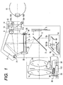
- Fig. 1 is a drawing to show the optical arrangement of a single-lens reflex camera provided with a line-of-sight detecting device according to the first embodiment of the present invention.
- reference numeral 1 designates a taking lens, which is represented by two lenses 1a, 1b for convenience' sake, but which is actually composed of many lenses.
- Numeral 2 denotes a main mirror, which is obliquely set in or is retracted from the photographing optical path, depending upon observation conditions and photographing conditions.
- Numeral 3 represents a sub-mirror, which reflects light transmitted by the main mirror 2 toward the bottom of the camera body.
- Numeral 4 stands for a shutter.
- Numeral 5 denotes a photosensitive member, which is a silver-salt film, a solid state imaging device of the CCD type, the MOS type, or the like, or a camera tube such as a vidicon.
- Numeral 6 indicates a focus detecting device, which is a device of the known phase difference detecting method mainly composed of field lens 6a located near the image plane, reflecting mirrors 6b and 6c, secondary imaging lens 6d, aperture stop 6e, and area sensor 6f consisting of plural CCDs or the like.
- This focus detecting device 6 is so constructed as to be capable of detecting the focus in multiple zones in observation screen 246, as shown in Fig. 2.
- Numeral 7 designates a focusing screen located on an intended image plane of the taking lens 1, 8 a pentagonal prism for changing the finder optical path, and 9, 10 an imaging lens and a photometry sensor for measuring the luminance of object in the observation screen.
- the imaging lens 9 keeps the focusing screen 7 and photometry sensor 10 in the conjugate relation with each other through the reflection optical path in the pentagonal roof prism 8.
- Numeral 11 denotes an eyepiece lens located behind the exit plane of pentagonal roof prism 8, which has a beam splitter 11a and which is used for permitting photographer's eye 15 to observe the focusing screen 7.
- the beam splitter 11a is, for example, a dichroic mirror for transmitting the visible light and reflecting the infrared light.
- Numeral 12 represents a light receiving lens and 14 an area sensor consisting of a two-dimensional array of photoelectric conversion elements, which is located so as to be conjugate with the vicinity of the iris of the photographer's eye 15 located at a predetermined position, with respect to the light receiving lens 12.
- 13a to 13d indicate infrared light emitting diodes (hereinafter referred to as IREDs), which are illumination light sources for illuminating the photographer's eye 15.
- IREDs infrared light emitting diodes
- Numeral 21 denotes high-intensity LEDs for superimposition that can be visually recognized even in a bright object.
- Light emitted from the superimposition LED 21 is reflected by light-projecting prism 22 and the main mirror 2, then is bent into the vertical direction by small prism array 7a provided in the display section of focusing screen 7, and travels through the eyepiece lens 11 to reach the photographer's eye 15.
- this small prism array 7a is arranged so that each prism is formed in a frame shape at a position corresponding to a focus detecting point in the focusing screen 7 and each prism is illuminated by a superimposition LED 21 corresponding thereto (each of which will be denoted by LED-1, LED-2,..., LED-44, or LED-45).
- Fig. 2 shows the finder field that can be observed when the observer looks into the finder.
- Thick frames out of the distance-measuring point marks indicate distance-measuring points displayed when the number of distance-measuring points is limited to 11 by thinning.
- Numeral 23 common to Fig. 1 and Fig. 2 represents a field mask for forming the finder field region.
- Numeral 24 is an in-finder LCD for displaying photographing information outside the finder field, which is illuminated by LED (F-LED) 25 for illumination shown in Fig. 1. Light transmitted by the in-finder LCD 24 is guided into the finder by triangular prism 26 to be displayed in a region 247 outside the finder field in Fig. 2, and the photographer thus observes the photographing information.
- LED LED
- numeral 31 designates an aperture stop provided in the taking lens 1, 32 an aperture driving device including an aperture driving circuit 114, 33 a motor for driving the lens, and 34 a lens driving member composed of a driving gear and other elements.
- Numeral 35 stands for a photocoupler, which detects rotation of pulse plate 36 synchronous with the lens driving member 34 and transfers the detection result to a lens focus adjustment circuit described below.
- Numeral 113 indicates the lens focus adjustment circuit, which drives the lens driving motor 33 by a predetermined amount based on the information from the photocoupler 35 and information about a lens drive amount from the camera side, thereby moving the focusing lens 1a of the taking lens 1 to the in-focus position.
- Numeral 37 denotes mount contacts being a well-known interface between the camera and the lens.
- Figs. 3A and 3B are block diagrams to show the main part of the electrical configuration built in the single-lens reflex camera of the above structure, wherein the same symbols denote the same elements as those in Fig. 1.
- numeral 100 designates a central processing unit of microcomputer (hereinafter referred to as MPU) being a camera controlling means built in the camera body, which performs internal operations based on the clock created by oscillator 101.
- Numeral 100a indicates a clock control circuit, which determines the operation frequency of the MPU 100 by not dividing the original oscillation frequency created by the oscillator 101 or by dividing it at the pitch of a half, one sixteenth, or the like by a signal in the MPU 100.
- Numeral 100b is an EEPROM being a storage means, which can store the photographing information including a film counter and the other information.
- Numeral 100c represents an A/D converter, which undergoes A/D conversion of an analog signal supplied from line-of-sight detection circuit 104, focus detection circuit 105, or photometry circuit 106 having multisegment photometry sensors, as described hereinafter.
- LED driving circuit 102 Connected to the MPU 100 are LED driving circuit 102, IRED driving circuit 103, line-of-sight detection circuit 104, focus detection circuit 105, photometry circuit 106, shutter control circuit 107, motor control circuit 108, film feeding detection circuit 109, switch sense circuit 110, and liquid-crystal display circuit 111. Transmission of signal is made through the mount contacts 37 shown in Fig. 1 from and to the lens control circuit 112 positioned in the taking lens 1.
- the LED driving circuit 102 turns the superimposition LEDs 21 on according to signals from the MPU 100.
- the IRED driving circuit 103 turns the IREDs 13 on according to signals from the MPU 100.
- the line-of-sight detection circuit 104 carries out storage operation and reading operation of the area sensor 14 according to signals from the MPU 100 and sends a pixel output analog signal of each pixel to the MPU 100.
- the MPU 100 converts this each analog signal to a digital signal by the A/D converter 100c, extracts, based on each pixel information, characteristic points of an eyeball image necessary for detection of line of sight according to predetermined algorithm, as described hereinafter, and calculates an angle of rotation of the photographer's eyeball from positions of the respective characteristic points.
- the line of sight (a point of fixation) of the photographer on the finder is operationally extracted, thereby selecting one of plural distance-measuring points 201 to 245, and automatic focus detection is carried out around the distance-measuring point thus selected.
- a distance-measuring point assignment switch is on, the selection of distance-measuring point based on the detection of line of sight is not carried out, because the position of distance-measuring point is fixed by the photographer.
- Numeral 115 is a regulator for supplying the power to the line-of-sight detection circuit 104 in response to a signal from the MPU 100, which is so controlled as to supply the power only upon execution of the line-of-sight detection operation.
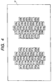
- the area sensor 6f is an area sensor composed of forty five sets of CCDs or the like corresponding to the plural distance-measuring points 201 to 245 in the screen, as described previously. Describing in detail, as shown in Fig. 4, 201a to 245a and 201b to 245b each correspond to the distance-measuring points.
- the focus detection circuit 105 carries out the storage control and reading control of the area sensor 6f according to signals from the MPU 100 to output each pixel information to the MPU 100.
- the MPU 100 executes A/D conversion of this information, performs the focus detection based on the known phase difference detecting method, and sends the focus detection information detected to the lens control circuit 112 to make focus adjustment of lens performed.
- the photometry circuit 106 outputs an output from the photometry sensor 10, as a luminance signal of each area in the screen, to the MPU 100.
- the shutter control circuit 107 moves a shutter leading curtain (through magnet MG-1) and a shutter trailing curtain (through magnet MG-2) according to signals from the MPU 100, thus performing the exposure operation.
- the motor control circuit 108 controls the motor according to signals from the MPU 100, thereby carrying out up and down operations of the main mirror 2, charging of shutter, and feeding of film.
- the film feeding detection circuit 109 detects whether the film has been wound up by one frame upon feeding of film and sends a signal to the MPU 100.
- SW1 is a switch which becomes on by a first stroke of the shutter release button not illustrated and which is for starting photometry, AF, and line-of-sight detection operations.
- SW2 is a switch which becomes on by a second stroke of the shutter release button not illustrated and which is for starting the exposure operation.
- the switch sense circuit 110 detects status signals of these switches SW1, SW2, and the number-of-distance-measuring-points changing switch, distance-measuring point assignment switch, and line-of-sight allowance switch shown in Fig. 3, and other unrepresented control members of camera and sends them to the MPU 100.
- the liquid-crystal display circuit 111 controls displays of the in-finder LCD 24 and LCD 42 for an unrepresented monitor according to signals from the MPU 100.
- the lens control circuit 112 performs communication with the MPU 100 through the lens mount contacts 37 and actuates the lens focus adjustment circuit 113 and aperture control circuit 114, thereby controlling the focus adjustment of lens and the aperture.
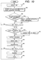
- the MPU 100 when the operation of the camera is started, the MPU 100 first performs detection of the switches in step #01 to obtain status information of the various switches. Then it executes the subroutine of "number-of-distance-measuring-points changing process" in next step #02.
- step #21 the number of distance-measuring points used for the detection of focus is set to 45 (201 to 245 shown in Fig. 2).
- step #22 the status of the number-of-distance-measuring-points changing switch is checked. If it is off then the flow will leave this subroutine to return to the main routine. On the other hand, if the number-of-distance-measuring-points changing switch is on then the flow will go to step #23 to decrease the distance-measuring points used for the detection of focus to 11 points (201, 204, 207, 218, 220, 223, 226, 228, 239, 242, and 245 in the thick frames of Fig. 2) by thinning and then leave this subroutine to return to the main routine.
- step #03 the MPU 100 checks the status of the switch SW1, which becomes on by the first stroke of the shutter release button; if it is off the flow will return to step #01. If the switch SW1 is on then the flow will proceed to step #04 to check the status of the line-of-sight allowance switch this time; if it is off then the flow will proceed immediately to step #06. If the line-of-sight allowance switch is on then the flow will branch off to step #05 to carry out the detection of line of sight here.
- step #05 the line of sight (point of fixation) is obtained by detecting the P images (Purkinje images: corneal reflex images) and a position of the center of the pupillary circle, and a distance-measuring point corresponding to the point of fixation obtained is selected out of the distance-measuring points set in above step #02. Then the flow goes to step #06.
- P images Purkinje images: corneal reflex images
- step #06 if the line-of-sight allowance switch is on then the focus detection operation will be carried out at the distance-measuring point selected in above step #05. If the line-of-sight allowance switch is off the focus detection operation will be carried out at the plural distance-measuring points set in above step #02. This focus detection is carried out by the known phase difference detecting method by the focus detection circuit 105 as described previously.
- next step #07 the MPU 100 controls the lens control circuit 112 according to the focus information obtained by the above focus detection operation, thereby performing the focus adjustment of lens.
- subsequent step #08 an exposure dose is determined based on the luminance information of object from the photometry circuit 106.
- step #09 the status of the switch SW2, which becomes on by the second stroke of the shutter release button, is then checked; if it is off the flow will return to step #01.
- step #09 to step #10 the flow will proceed from step #09 to step #10 to perform the following release control for exposure on the film.
- the main mirror 2 is moved up prior to the exposure operation, so as to be retracted from the photographing optical path.
- the aperture 31 in the lens is driven through the lens control circuit 112 up to an aperture amount based on the exposure dose determined.
- the shutter is controlled by the shutter control circuit 107 so as to be open during a shutter open time (shutter speed) based on the exposure dose determined, thereby completing exposure.
- the main mirror 2 retracted from the photographing optical path is moved down so as to be again obliquely set in the photographing optical path.
- next step #11 the MPU 100 starts feeding of film through the motor control circuit 108 in order to wind the film up by one frame and stops the feeding when receiving a film feed completion signal from the film feeding detection circuit 109. Then the flow returns to step #01.
- the focus when there are plural distance-measuring points, the focus can be detected at some of them by arbitrarily thinning the distance-measuring points. Therefore, the detection time and operation time are shorter than those in the case of distance measurement at the all distance-measuring points.
- the device is readily adaptable for a moving object. The thinning of distance-measuring points also improves the operability of selection of distance-measuring point.
- the single-lens reflex camera according to the second embodiment of the present invention will be described below.
- the optical arrangement and electrical configuration of the camera are the same as in the first embodiment described above and, therefore, the details thereof are omitted herein.
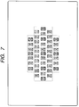
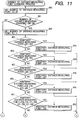
- Fig. 7 is a drawing to show a distribution of arbitrary distance-measuring points in the single-lens reflex camera in the second embodiment of the present invention, showing partitioning (portions surrounded by dotted lines) for changing an arbitrarily selected distance-measuring point within eleven points when the distance-measuring points are changed from forty five points to eleven points.
- Figs. 8A and 8B and Figs. 9A and 9B are drawings each for explaining movement of selected distance-measuring point upon arbitrary selection of distance-measuring point from 45 points or from 11 points, respectively, wherein black portions indicate distance-measuring points selected.
- Fig. 8A shows horizontal movement, wherein movement stops at the left and right extremes.
- Fig. 8A shows horizontal movement, wherein movement stops at the left and right extremes.
- Fig. 9A shows horizontal movement in the eleven distance-measuring points, wherein the movement stops at the left and right extremes
- Fig. 9B shows vertical movement in the eleven distance-measuring points, wherein the movement stops at the top and bottom ends.
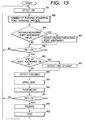
- the MPU 100 when the operation of camera is started, the MPU 100 first executes the switch detection in step #31 and then carries out the subroutine of "number-of-distance-measuring-points changing process" in next step #32.
- step #50 the number of distance-measuring points available for distance measurement is set to 45. Then, in step #51, the status of the number-of-distance-measuring-points changing switch is checked; if it is off then the flow will leave this subroutine to return to the main routine.
- step #51 If the number-of-distance-measuring-points changing switch is on then the flow will proceed from step #51 to step #52 to change the number of distance-measuring points available for distance measurement to 11. Then, in step #53, it is checked whether the arbitrary distance-measuring point specified by the photographer is either 201 or 202. If so the flow will branch off to step #54 to set the arbitrary distance-measuring point to 201, and then the flow will leave this subroutine to return to the main routine.
- step #53 the flow will proceed from step #53 to step #55 to check this time whether the arbitrary distance-measuring point specified by the photographer is 203, 204, or 205. If so then the flow will branch off to step #56 to set the arbitrary distance-measuring point to 204 and will leave this subroutine to return to the main routine.
- step #55 the flow will proceed from step #55 to step #57 to check this time whether the arbitrary distance-measuring point specified by the photographer is 206 or 207. If so the flow will branch off to step #58 to set the arbitrary distance-measuring point to 207 and will leave this subroutine to return to the main routine.
- step #57 the flow will proceed from step #57 to step #59 to check this time whether the arbitrary distance-measuring point is 208, 218, 219, or 229. If so the flow will branch off to step #60 to set the arbitrary distance-measuring point to 218 and will leave this subroutine to return to the main routine.
- step #59 the flow will proceed from step #59 to step #61 to check this time whether the arbitrary distance-measuring point specified by the photographer is 209, 210, 211, 220, 221, 230, 231, or 232. If so the flow will branch off to step #62 to set the arbitrary distance-measuring point to 220 and will leave this subroutine to return to the main routine.
- step #61 the flow will proceed from step #61 to step #63 of Fig. 12 to check this time whether the arbitrary distance-measuring point specified by the photographer is 212, 213, 222, 223, 224, 233, or 234. If so the flow will branch off to step #64 to set the arbitrary distance-measuring point to 223 and will leave this subroutine to return to the main routine.
- step #63 the flow will proceed from step #63 to step #65 to check this time whether the arbitrary distance-measuring point specified by the photographer is 214, 215, 216, 225, 226, 235, 236, or 237. If so the flow will branch off to step #66 to set the arbitrary distance-measuring point to 226 and will leave this subroutine to return to the main routine.
- step #65 the flow will proceed from step #65 to step #67 to check this time whether the arbitrary distance-measuring point specified by the photographer is 217, 227, 228, or 238. If so the flow will branch off to step #68 to set the arbitrary distance-measuring point to 228 and will leave this subroutine to return to the main routine.
- step #67 the flow will proceed from step #67 to step #69 to check this time whether the arbitrary distance-measuring point specified by the photographer is 239 or 240. If so the flow will branch off to step #70 to set the arbitrary distance-measuring point to 239 and will leave this subroutine to return to the main routine.
- step #69 the flow will proceed from step #69 to step #71 to check this time whether the arbitrary distance-measuring point specified by the photographer is 241, 242 or 243. If so the flow will branch off to step #72 to set the arbitrary distance-measuring point to 242 and will leave this subroutine to return to the main routine.
- step #71 the arbitrary distance-measuring point specified by the photographer is one other than 241, 242 and 243 the flow will proceed from step #71 to step #73 to set the arbitrary distance-measuring point to 245 and will leave this subroutine to return to the main routine.
- step #33 it is determined whether the distance-measuring-point assignment switch is on; if it is off then the flow will proceed immediately to step #35. On the other hand, if it is on then the flow will proceed to step #34 to detect which point was selected as a distance-measuring point out of the distance-measuring points (45 points or 11 points) available for distance measurement by the photographer. This selection is carried out using unrepresented up-down switch and left-right switch or the like to select one out of the 45 points or 11 points, as shown in Figs. 8A, 8B and Figs. 9A, 9B.
- the distance-measuring point selected in this step #34 is set as the arbitrary distance-measuring point to be subjected to the determination in #53, #55, #57, #59, #61, #63, #65, #67, #69, or #71 in Fig. 11 and Fig. 12.
- next step #35 the MPU 100 checks the status of the switch SW1, which becomes on by the first stroke of the shutter release button; if it is off the flow will return to step #31. If the switch SW1 is on then the flow will proceed to step #36 to check the status of the line-of-sight allowance switch this time; if it is off the flow will proceed immediately to step #38. If the line-of-sight allowance switch is on the flow will branch off to step #37 to carry out the detection of line of sight here to obtain the line of sight (point of fixation) by detecting the P images (the Purkinje images: corneal reflex images) and a position of the center of the pupillary circle and to set a distance-measuring point corresponding to the point of fixation. Then the flow will proceed to step #38. This distance-measuring point set in #37 is also set as the arbitrary distance-measuring point to be subjected to the determination in Fig. 11 and Fig. 12.
- step #38 one distance-measuring point is selected out of the distance-measuring point determined in above step #34 and the distance-measuring point available for distance measurement obtained from the line-of-sight information in above step #37 and the focus detection operation is carried out thereat.
- This focus detection is carried out by the known phase difference detecting method by the focus detection circuit 105 as described previously.
- next step #39 the MPU 100 controls the lens control circuit 112, based on the focus information obtained by the above focus detection operation, to perform the focus adjustment of lens.
- an exposure dose is determined according to the luminance information of object from the photometry circuit 106.
- step #41 the status of the switch SW2, which becomes on by the second stroke of the shutter release button, is checked; if it is off the flow will return to step #31.
- step #41 to step #42 the flow will proceed from step #41 to step #42 to perform the following release control for exposure on the film.
- the main mirror 2 is moved up prior to the exposure operation, so as to be retracted from the photographing optical path.
- the aperture 31 in the lens is driven through the lens control circuit 112 up to an aperture amount based on the exposure dose determined.
- the shutter is controlled by the shutter control circuit 107 so as to be open during a shutter open time (shutter speed) based on the exposure dose determined, thereby completing exposure.
- the main mirror 2 retracted from the photographing optical path is moved down so as to be again obliquely set in the photographing optical path.
- next step #43 the MPU 100 starts feeding of film through the motor control circuit 108 in order to wind the film up by one frame and stops the feeding when receiving the film feed completion signal from the film feeding detection circuit 109. Then the flow returns to step #31.
- the arbitrary distance-measuring point set by the photographer can be moved into the decreased number of distance-measuring points; therefore, even if the number of distance-measuring points is decreased, an object having been tracked before the decrease can be captured relatively easily.
- the single-lens reflex camera according to the third embodiment of the present invention will be described.
- the optical arrangement and electrical configuration of the camera are the same as in the first embodiment described above and, therefore, the details thereof are omitted herein.
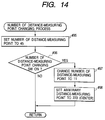
- the MPU 100 when the operation of camera is started, the MPU 100 first carries out the switch detection in step #81 and then performs the subroutine of "number-of-distance-measuring-points changing process" in next step #82.
- step #95 the number of distance-measuring points available for distance measurement is set to 45.
- step #96 if the number-of-distance-measuring-points changing switch is off then the flow will leave this subroutine to return to the main routine.
- step #97 if the number-of-distance-measuring-points changing switch is on the flow will branch off to step #97 to change the number of distance-measuring points available for distance measurement to 11.
- step #98 the arbitrary distance-measuring point specified by the photographer is forcedly set to 223 (the center distance-measuring point) and then the flow will leave the subroutine to return to the main routine.
- step #83 it is determined whether the distance-measuring-point assignment switch is on; if it is off then the flow will proceed immediately to step #85. On the other hand, if it is on then the flow will proceed to step #84 to detect which point was selected as a distance-measuring point out of the distance-measuring points (45 points or 11 points) available for distance measurement by the photographer. This selection is carried out using the unrepresented up-down switch and left-right switch or the like to select one out of the 45 points or 11 points, as shown above in Figs. 8A, 8B and Figs. 9A, 9B.
- step #85 the MPU 100 checks the status of the switch SW1, which becomes on by the first stroke of the shutter release button; if it is off the flow will return to step #81. If the switch SW1 is on then the flow will proceed to step #86 to check the status of the line-of-sight allowance switch this time; if it is off the flow will proceed immediately to step #88. If the line-of-sight allowance switch is on the flow will branch off to step #87 to carry out the detection of line of sight here to obtain the line of sight (point of fixation) by detecting the P images (the Purkinje images: corneal reflex images) and a position of the center of the pupillary circle. Then the flow will proceed to step #88.
- the P images the Purkinje images: corneal reflex images
- step #88 one distance-measuring point is selected out of the distance-measuring point determined in above step #84 and the distance-measuring point available for distance measurement obtained from the line-of-sight information in above step #87 and the focus detection operation is carried out thereat.
- This focus detection is carried out by the known phase difference detecting method by the focus detection circuit 105 as described previously.
- next step #89 the MPU 100 controls the lens control circuit 112, based on the focus information obtained by the above focus detection operation, to perform the focus adjustment of lens.
- an exposure dose is determined according to the luminance information of object from the photometry circuit 106.
- step #91 the status of the switch SW2, which becomes on by the second stroke of the shutter release button, is checked; if it is off the flow will return to step #81.
- step #91 to step #92 the flow will proceed from step #91 to step #92 to perform the following release control for exposure on the film.
- the main mirror 2 is moved up prior to the exposure operation, so as to be retracted from the photographing optical path.
- the aperture 31 in the lens is driven through the lens control circuit 112 up to an aperture amount based on the exposure dose determined.
- the shutter is controlled by the shutter control circuit 107 so as to be open during a shutter open time (shutter speed) based on the exposure dose determined, thereby completing exposure.
- the main mirror 2 retracted from the photographing optical path is moved down so as to be again obliquely set in the photographing optical path.
- next step #93 the MPU 100 starts feeding of film through the motor control circuit 108 in order to wind the film up by one frame and stops the feeding when receiving the film feed completion signal from the film feeding detection circuit 109. Then the flow returns to step #81.
- Step #98 described above is so arranged that if an arbitrary distance-measuring point is selected in #84 or #87 after this step is carried out once this step will not be executed until the number-of-distance-measuring-points changing switch is turned from off to on.
- the arbitrary distance-measuring point set by the photographer can be moved to the center distance-measuring point in the distance-measuring range which is also within the decreased member of distance-measuring points; therefore, next setting of the arbitrary distance-measuring point by the photographer is from the center distance-measuring point, and the device is thus easier to operate.
- the present invention is also applicable to distance-measuring devices having distance-measuring points used for measuring the distance to the object, automatic focus adjusting apparatus for adjusting the position of lens based on information from the distance-measuring device, and cameras provides with the automatic focus adjusting apparatus, and so on.
- the present invention was described with the examples of application to the single-lens reflex camera, but the invention can also be applied to such cameras as lens shutter cameras, video cameras, or electronic still cameras. Further, the present invention can also be applied to telescopes, binoculars, other optical devices, and constitutive units thereof.
- the present invention provides a camera having a focus detecting device for independently detecting each of focus conditions in plural regions of a screen by use of an area sensor. More particularly, the invention provides a camera having a focus detecting device provided with a first mode for setting a first number as a number of focus detection areas and a second mode for setting a second number, smaller than the first number, of areas except for predetermined areas in the focus detection areas in the first mode, as focus detection areas, and arranged to allow selection of the first and second modes, thereby permitting a changeover of the number of focus detection areas according to a photographer's will.
Abstract
Description
Claims (12)
- A camera comprising a focus detecting device for carrying out detection of focus for each area in a first number of plural focus detection areas, comprising:a focus detection area setting circuit having a first mode for setting said first number of plural areas as focus detection areas and a second mode for setting a second number of plural areas as focus detection areas by excluding predetermined areas out of the areas in the first mode; anda selection circuit for allowing an operator to arbitrarily select one of said first and second modes.
- A camera according to Claim 1, wherein said first number of plural areas are distributed so as to substantially evenly cover a predetermined range of a screen and said second number of areas are also distributed so as to substantially evenly cover said predetermined range.
- A camera according to Claim 1, said camera comprising assigning means arranged so that in said first mode said assigning means assigns an arbitrary area as a focus detection area out of said first number of areas and in said second mode said assigning means assigns an arbitrary area as a focus detection area out of said second number of areas.
- A camera according to Claim 3, said camera comprising an assignment control circuit arranged so that when in said first mode an arbitrary area is assigned and thereafter the mode is changed to the second mode and when the area assigned in said first mode is not set as an area in said second mode by the setting circuit, the assignment control circuit assigns an area close to said area assigned in said first mode out of the second number of areas set in the second mode, as a focus detection area.
- A camera according to Claim 3, said camera comprising an assignment control circuit arranged so that when in said first mode an arbitrary area is assigned and thereafter the mode is changed to the second mode and when the area assigned in said first mode is not set as an area in said second mode by the setting circuit, the assignment control circuit assigns a specific area preliminarily determined out of the second number of areas set in the second mode, as a focus detection area.
- A camera according to Claim 5, wherein said specific area is a center area.
- A camera comprising a focus detecting device having a first number of plural focus detection areas arranged in a two-dimensional direction so as to substantially evenly cover a predetermined range of a screen and arranged to perform detection of focus for each area, comprising:a focus detection area setting circuit having a first mode for setting said first number of plural areas as focus detection areas and a second mode for setting a second number of plural areas as focus detection areas by excluding predetermined areas in the areas in the first mode; anda selection circuit for selection of said first and second modes.
- A camera according to Claim 7, said camera comprising assigning means arranged so that in said first mode said assigning means assigns an arbitrary area as a focus detection area out of said first number of areas and in said second mode said assigning means assigns an arbitrary area as a focus detection area out of said second number of areas.
- A camera according to Claim 8, said camera comprising an assignment control circuit arranged so that when in said first mode an arbitrary area is assigned and thereafter the mode is changed to the second mode and when the area assigned in said first mode is not set as an area in said second mode by the setting circuit, the assignment control circuit assigns an area close to said area assigned in said first mode out of the second number of areas set in the second mode, as a focus detection area.
- A camera according to Claim 8, said camera comprising an assignment control circuit arranged so that when in said first mode an arbitrary area is assigned and thereafter the mode is changed to the second mode and when the area assigned in said first mode is not set as an area in said second mode by the setting circuit, the assignment control circuit assigns a specific area preliminarily determined out of the second number of areas set in the second mode, as a focus detection area.
- A camera comprising a focus detecting device for carrying out detection of focus for each area in a first number of plural focus detection areas, comprising:a focus detection area setting circuit having a first mode for setting said first number of plural areas as focus detection areas and a second mode for setting a second number of plural areas as focus detection areas by excluding predetermined areas in the areas in the first mode;a selection circuit for selecting one of said first and second modes;assigning means arranged so that in said first mode said assigning means assigns an arbitrary area as a focus detection area out of said first number of areas and in said second mode said assigning means assigns an arbitrary area as a focus detection area out of said second number of areas; andan assignment control circuit arranged so that when in said first mode an arbitrary area is assigned and thereafter the mode is changed to the second mode and when the area assigned in said first mode is not set as an area in said second mode by the setting circuit, the assignment control circuit assigns an area close to said area assigned in said first mode out of the second number of areas set in the second mode, as a focus detection area.
- A camera comprising a focus detecting device for carrying out detection of focus for each area in a first number of plural focus detection areas, comprising:a focus detection area setting circuit having a first mode for setting said first number of plural areas as focus detection areas and a second mode for setting a second number of plural areas as focus detection areas by excluding predetermined areas in the areas in the first mode;a selection circuit for selecting one of said first and second modes;assigning means arranged so that in said first mode said assigning means assigns an arbitrary area as a focus detection area out of said first number of areas and in said second mode said assigning means assigns an arbitrary area as a focus detection area out of said second number of areas; andan assignment control circuit arranged so that when in said first mode an arbitrary area is assigned and thereafter the mode is changed to the second mode and when the area assigned in said first mode is not set as an area in said second mode by the setting circuit, the assignment control circuit assigns a specific area preliminarily determined out of the second number of areas set in the second mode, as a focus detection area.
Priority Applications (1)
| Application Number | Priority Date | Filing Date | Title |
|---|---|---|---|
| EP06119173A EP1717622A1 (en) | 1996-12-11 | 1997-12-10 | Camera provided with focus detecting device |
Applications Claiming Priority (2)
| Application Number | Priority Date | Filing Date | Title |
|---|---|---|---|
| JP8346495A JPH10170813A (en) | 1996-12-11 | 1996-12-11 | Focus detector, automatic focusing device, and camera |
| JP346495/96 | 1996-12-11 |
Related Child Applications (1)
| Application Number | Title | Priority Date | Filing Date |
|---|---|---|---|
| EP06119173A Division EP1717622A1 (en) | 1996-12-11 | 1997-12-10 | Camera provided with focus detecting device |
Publications (2)
| Publication Number | Publication Date |
|---|---|
| EP0848272A1 true EP0848272A1 (en) | 1998-06-17 |
| EP0848272B1 EP0848272B1 (en) | 2006-11-02 |
Family
ID=18383821
Family Applications (2)
| Application Number | Title | Priority Date | Filing Date |
|---|---|---|---|
| EP97121744A Expired - Lifetime EP0848272B1 (en) | 1996-12-11 | 1997-12-10 | Camera provided with focus detecting device |
| EP06119173A Withdrawn EP1717622A1 (en) | 1996-12-11 | 1997-12-10 | Camera provided with focus detecting device |
Family Applications After (1)
| Application Number | Title | Priority Date | Filing Date |
|---|---|---|---|
| EP06119173A Withdrawn EP1717622A1 (en) | 1996-12-11 | 1997-12-10 | Camera provided with focus detecting device |
Country Status (4)
| Country | Link |
|---|---|
| US (1) | US5930533A (en) |
| EP (2) | EP0848272B1 (en) |
| JP (1) | JPH10170813A (en) |
| DE (1) | DE69736885T2 (en) |
Cited By (2)
| Publication number | Priority date | Publication date | Assignee | Title |
|---|---|---|---|---|
| EP1882966A1 (en) | 2006-07-28 | 2008-01-30 | Canon Kabushiki Kaisha | Focus detection apparatus |
| WO2008056271A1 (en) * | 2006-11-07 | 2008-05-15 | Sony Ericsson Mobile Communications Ab | User defined autofocus area |
Families Citing this family (9)
| Publication number | Priority date | Publication date | Assignee | Title |
|---|---|---|---|---|
| JPH11110120A (en) * | 1997-10-07 | 1999-04-23 | Canon Inc | Device and method for inputting line-of-sight information |
| JP4497567B2 (en) * | 1998-09-14 | 2010-07-07 | キヤノン株式会社 | Focus detection device, distance measuring device and optical instrument |
| JP4124874B2 (en) * | 1998-08-31 | 2008-07-23 | キヤノン株式会社 | camera |
| JP2000081647A (en) * | 1998-09-03 | 2000-03-21 | Canon Inc | Camera |
| SE518050C2 (en) * | 2000-12-22 | 2002-08-20 | Afsenius Sven Aake | Camera that combines sharply focused parts from various exposures to a final image |
| US7697827B2 (en) | 2005-10-17 | 2010-04-13 | Konicek Jeffrey C | User-friendlier interfaces for a camera |
| JP4542126B2 (en) * | 2007-09-18 | 2010-09-08 | キヤノン株式会社 | Focus detection device |
| DE102015214671B4 (en) * | 2015-07-31 | 2020-02-27 | Fraunhofer-Gesellschaft zur Förderung der angewandten Forschung e.V. | Autofocusing optical device and method for optical autofocusing |
| JP7011402B2 (en) | 2017-05-16 | 2022-01-26 | キヤノン株式会社 | Image pickup device and its control method |
Citations (7)
| Publication number | Priority date | Publication date | Assignee | Title |
|---|---|---|---|---|
| JPS58219505A (en) * | 1982-06-14 | 1983-12-21 | Nippon Seimitsu Kogyo Kk | Automatic focusing device capable of varying area for detecting focus |
| JPH06141225A (en) * | 1992-10-27 | 1994-05-20 | Canon Inc | Solid-state image pickup device |
| EP0667546A2 (en) * | 1990-01-18 | 1995-08-16 | Nikon Corporation | Camera with manual and automatic focusing |
| US5455654A (en) * | 1991-05-02 | 1995-10-03 | Canon Kabushiki Kaisha | Multi-area focus detection apparatus for detecting focus either automatically or intentionally |
| US5532783A (en) * | 1993-11-24 | 1996-07-02 | Nikon Corporation | Apparatus and method for adjusting the focus of a camera during scanning drive and non-scanning drive of a photographic lens |
| EP0720360A1 (en) * | 1994-12-30 | 1996-07-03 | Eastman Kodak Company | An electronic camera with rapid automatic focus of an image upon an image sensor |
| JPH08262319A (en) * | 1995-03-27 | 1996-10-11 | Nikon Corp | Focus detector |
Family Cites Families (12)
| Publication number | Priority date | Publication date | Assignee | Title |
|---|---|---|---|---|
| US4827303A (en) * | 1983-02-08 | 1989-05-02 | Canon Kabushiki Kaisha | Distance measuring device |
| US4728785A (en) | 1986-01-10 | 1988-03-01 | Canon Kabushiki Kaisha | Focus detecting device using adjustable inclined sensing means |
| JPH0779434B2 (en) * | 1986-05-16 | 1995-08-23 | キヤノン株式会社 | Focus detection device |
| JPH03182710A (en) * | 1989-12-12 | 1991-08-08 | Olympus Optical Co Ltd | Focus detecting device |
| JP2749921B2 (en) * | 1989-12-29 | 1998-05-13 | キヤノン株式会社 | Imaging device |
| US5189460A (en) * | 1990-01-30 | 1993-02-23 | Canon Kabushiki Kaisha | Camera detecting luminance from a plurality of areas |
| JPH05323182A (en) * | 1992-05-22 | 1993-12-07 | Canon Inc | Camera |
| DE4340729A1 (en) * | 1992-11-30 | 1994-06-01 | Asahi Optical Co Ltd | Compact camera with automatic focal length-dependent exposure settings - calculates values of exposure using weighted average of photometric brightness steps with coeffts. varying according to focus |
| JPH06230453A (en) * | 1993-02-02 | 1994-08-19 | Nikon Corp | Camera provided with object tracking function |
| JPH06313838A (en) * | 1993-04-28 | 1994-11-08 | Nikon Corp | Voice input camera |
| JPH07199320A (en) * | 1993-11-24 | 1995-08-04 | Nikon Corp | Camera |
| JPH08136798A (en) * | 1994-11-08 | 1996-05-31 | Canon Inc | Automatic focusing camera |
-
1996
- 1996-12-11 JP JP8346495A patent/JPH10170813A/en active Pending
-
1997
- 1997-12-10 EP EP97121744A patent/EP0848272B1/en not_active Expired - Lifetime
- 1997-12-10 EP EP06119173A patent/EP1717622A1/en not_active Withdrawn
- 1997-12-10 US US08/988,352 patent/US5930533A/en not_active Expired - Lifetime
- 1997-12-10 DE DE69736885T patent/DE69736885T2/en not_active Expired - Lifetime
Patent Citations (7)
| Publication number | Priority date | Publication date | Assignee | Title |
|---|---|---|---|---|
| JPS58219505A (en) * | 1982-06-14 | 1983-12-21 | Nippon Seimitsu Kogyo Kk | Automatic focusing device capable of varying area for detecting focus |
| EP0667546A2 (en) * | 1990-01-18 | 1995-08-16 | Nikon Corporation | Camera with manual and automatic focusing |
| US5455654A (en) * | 1991-05-02 | 1995-10-03 | Canon Kabushiki Kaisha | Multi-area focus detection apparatus for detecting focus either automatically or intentionally |
| JPH06141225A (en) * | 1992-10-27 | 1994-05-20 | Canon Inc | Solid-state image pickup device |
| US5532783A (en) * | 1993-11-24 | 1996-07-02 | Nikon Corporation | Apparatus and method for adjusting the focus of a camera during scanning drive and non-scanning drive of a photographic lens |
| EP0720360A1 (en) * | 1994-12-30 | 1996-07-03 | Eastman Kodak Company | An electronic camera with rapid automatic focus of an image upon an image sensor |
| JPH08262319A (en) * | 1995-03-27 | 1996-10-11 | Nikon Corp | Focus detector |
Non-Patent Citations (3)
| Title |
|---|
| PATENT ABSTRACTS OF JAPAN vol. 008, no. 075 (P - 266) 7 April 1984 (1984-04-07) * |
| PATENT ABSTRACTS OF JAPAN vol. 018, no. 455 (E - 1595) 24 August 1994 (1994-08-24) * |
| PATENT ABSTRACTS OF JAPAN vol. 097, no. 002 28 February 1997 (1997-02-28) * |
Cited By (7)
| Publication number | Priority date | Publication date | Assignee | Title |
|---|---|---|---|---|
| EP1882966A1 (en) | 2006-07-28 | 2008-01-30 | Canon Kabushiki Kaisha | Focus detection apparatus |
| US7582854B2 (en) | 2006-07-28 | 2009-09-01 | Canon Kabushiki Kaisha | Focus detection apparatus for detecting a relative positional relationship between a pair of object images |
| CN100539642C (en) * | 2006-07-28 | 2009-09-09 | 佳能株式会社 | Focus detection device and its control method |
| WO2008056271A1 (en) * | 2006-11-07 | 2008-05-15 | Sony Ericsson Mobile Communications Ab | User defined autofocus area |
| US7664384B2 (en) | 2006-11-07 | 2010-02-16 | Sony Ericsson Mobile Communications Ab | User defined autofocus area |
| EP3176634A1 (en) * | 2006-11-07 | 2017-06-07 | DRNC Holdings, Inc. | User defined autofocus area |
| EP3454116A1 (en) * | 2006-11-07 | 2019-03-13 | DRNC Holdings, Inc. | User defined autofocus area |
Also Published As
| Publication number | Publication date |
|---|---|
| EP1717622A1 (en) | 2006-11-02 |
| US5930533A (en) | 1999-07-27 |
| EP0848272B1 (en) | 2006-11-02 |
| JPH10170813A (en) | 1998-06-26 |
| DE69736885D1 (en) | 2006-12-14 |
| DE69736885T2 (en) | 2007-05-16 |
Similar Documents
| Publication | Publication Date | Title |
|---|---|---|
| US5335035A (en) | Visual line direction detecting device for the camera | |
| JPH10311999A (en) | Camera | |
| US5930533A (en) | Camera provided with focus detecting device | |
| JPH06304142A (en) | Device for detecting line of sight | |
| US6097894A (en) | Optical apparatus and camera capable of line of sight detection | |
| JPH08271784A (en) | Optical instrument with function of detecting line of sight | |
| US5402199A (en) | Visual axis detecting apparatus | |
| US5515131A (en) | Optical apparatus having a function of inputting data of a visual axis | |
| US5752090A (en) | Optical device having a line of sight detection apparatus | |
| JP4054436B2 (en) | Optical device | |
| US5576796A (en) | Optical apparatus having function to detect visual axis | |
| JP3559622B2 (en) | Gaze detection device and optical apparatus having gaze detection device | |
| JP3912853B2 (en) | camera | |
| JPH10170814A (en) | Focus detector, automatic focusing device, and camera | |
| JP3624023B2 (en) | Line-of-sight detection apparatus and optical apparatus comprising line-of-sight detection apparatus | |
| JP2000131599A (en) | Device and camera having line-of-sight selecting function | |
| JP3176147B2 (en) | Eye gaze detection device | |
| JP3495824B2 (en) | Optical equipment having a line-of-sight detection device | |
| JP3647088B2 (en) | Camera having line-of-sight detection means | |
| JPH10148864A (en) | Photometry device for camera | |
| JPH08191797A (en) | Observation device with sight-line detecting function | |
| JPH1114897A (en) | Optical equipment | |
| JPH08234273A (en) | Optical apparatus | |
| JPH0951875A (en) | Line of sight detector and optical device | |
| JPH1099273A (en) | Visual axis detecting device and optical instrument |
Legal Events
| Date | Code | Title | Description |
|---|---|---|---|
| PUAI | Public reference made under article 153(3) epc to a published international application that has entered the european phase |
Free format text: ORIGINAL CODE: 0009012 |
|
| AK | Designated contracting states |
Kind code of ref document: A1 Designated state(s): DE FR GB |
|
| AX | Request for extension of the european patent |
Free format text: AL;LT;LV;MK;RO;SI |
|
| 17P | Request for examination filed |
Effective date: 19981103 |
|
| AKX | Designation fees paid |
Free format text: DE FR GB |
|
| RBV | Designated contracting states (corrected) |
Designated state(s): DE FR GB |
|
| 17Q | First examination report despatched |
Effective date: 20020814 |
|
| GRAP | Despatch of communication of intention to grant a patent |
Free format text: ORIGINAL CODE: EPIDOSNIGR1 |
|
| GRAS | Grant fee paid |
Free format text: ORIGINAL CODE: EPIDOSNIGR3 |
|
| GRAA | (expected) grant |
Free format text: ORIGINAL CODE: 0009210 |
|
| AK | Designated contracting states |
Kind code of ref document: B1 Designated state(s): DE FR GB |
|
| REG | Reference to a national code |
Ref country code: GB Ref legal event code: FG4D |
|
| REF | Corresponds to: |
Ref document number: 69736885 Country of ref document: DE Date of ref document: 20061214 Kind code of ref document: P |
|
| ET | Fr: translation filed | ||
| PLBE | No opposition filed within time limit |
Free format text: ORIGINAL CODE: 0009261 |
|
| STAA | Information on the status of an ep patent application or granted ep patent |
Free format text: STATUS: NO OPPOSITION FILED WITHIN TIME LIMIT |
|
| 26N | No opposition filed |
Effective date: 20070803 |
|
| REG | Reference to a national code |
Ref country code: FR Ref legal event code: PLFP Year of fee payment: 19 |
|
| PGFP | Annual fee paid to national office [announced via postgrant information from national office to epo] |
Ref country code: GB Payment date: 20151218 Year of fee payment: 19 |
|
| PGFP | Annual fee paid to national office [announced via postgrant information from national office to epo] |
Ref country code: FR Payment date: 20151223 Year of fee payment: 19 |
|
| PGFP | Annual fee paid to national office [announced via postgrant information from national office to epo] |
Ref country code: DE Payment date: 20151231 Year of fee payment: 19 |
|
| REG | Reference to a national code |
Ref country code: DE Ref legal event code: R119 Ref document number: 69736885 Country of ref document: DE |
|
| GBPC | Gb: european patent ceased through non-payment of renewal fee |
Effective date: 20161210 |
|
| REG | Reference to a national code |
Ref country code: FR Ref legal event code: ST Effective date: 20170831 |
|
| PG25 | Lapsed in a contracting state [announced via postgrant information from national office to epo] |
Ref country code: FR Free format text: LAPSE BECAUSE OF NON-PAYMENT OF DUE FEES Effective date: 20170102 |
|
| PG25 | Lapsed in a contracting state [announced via postgrant information from national office to epo] |
Ref country code: DE Free format text: LAPSE BECAUSE OF NON-PAYMENT OF DUE FEES Effective date: 20170701 Ref country code: GB Free format text: LAPSE BECAUSE OF NON-PAYMENT OF DUE FEES Effective date: 20161210 |