EP0848240A2 - Verfahren zur Prüfung von Fahrzeugteilen - Google Patents
Verfahren zur Prüfung von Fahrzeugteilen Download PDFInfo
- Publication number
- EP0848240A2 EP0848240A2 EP97121651A EP97121651A EP0848240A2 EP 0848240 A2 EP0848240 A2 EP 0848240A2 EP 97121651 A EP97121651 A EP 97121651A EP 97121651 A EP97121651 A EP 97121651A EP 0848240 A2 EP0848240 A2 EP 0848240A2
- Authority
- EP
- European Patent Office
- Prior art keywords
- vehicle
- deterioration
- vehicle part
- test
- miles
- Prior art date
- Legal status (The legal status is an assumption and is not a legal conclusion. Google has not performed a legal analysis and makes no representation as to the accuracy of the status listed.)
- Withdrawn
Links
- 238000010998 test method Methods 0.000 title 1
- 238000012360 testing method Methods 0.000 claims abstract description 105
- 230000006866 deterioration Effects 0.000 claims abstract description 56
- 230000001186 cumulative effect Effects 0.000 claims abstract description 14
- 230000001939 inductive effect Effects 0.000 claims abstract description 10
- 238000000034 method Methods 0.000 claims description 28
- 230000000875 corresponding effect Effects 0.000 claims description 24
- 230000007613 environmental effect Effects 0.000 claims description 23
- XLYOFNOQVPJJNP-UHFFFAOYSA-N water Substances O XLYOFNOQVPJJNP-UHFFFAOYSA-N 0.000 claims description 9
- 230000002596 correlated effect Effects 0.000 claims description 3
- 230000003252 repetitive effect Effects 0.000 abstract description 9
- 239000012530 fluid Substances 0.000 description 24
- 230000007774 longterm Effects 0.000 description 21
- 230000002542 deteriorative effect Effects 0.000 description 3
- 238000005259 measurement Methods 0.000 description 3
- 150000003839 salts Chemical class 0.000 description 3
- 239000000725 suspension Substances 0.000 description 3
- 238000006073 displacement reaction Methods 0.000 description 2
- 238000012544 monitoring process Methods 0.000 description 2
- 230000006835 compression Effects 0.000 description 1
- 238000007906 compression Methods 0.000 description 1
- 238000010276 construction Methods 0.000 description 1
- 238000010586 diagram Methods 0.000 description 1
- 238000009434 installation Methods 0.000 description 1
- 238000004519 manufacturing process Methods 0.000 description 1
- 238000005070 sampling Methods 0.000 description 1
- -1 snow Substances 0.000 description 1
- 239000007921 spray Substances 0.000 description 1
- 238000005507 spraying Methods 0.000 description 1
- 238000013022 venting Methods 0.000 description 1
Images

Classifications
-
- G—PHYSICS
- G01—MEASURING; TESTING
- G01M—TESTING STATIC OR DYNAMIC BALANCE OF MACHINES OR STRUCTURES; TESTING OF STRUCTURES OR APPARATUS, NOT OTHERWISE PROVIDED FOR
- G01M13/00—Testing of machine parts
- G01M13/02—Gearings; Transmission mechanisms
- G01M13/027—Test-benches with force-applying means, e.g. loading of drive shafts along several directions
Definitions
- the present invention relates to the testing of vehicle parts, and particularly relates to the testing of vehicle parts that are subject to deterioration through long term use.
- a vehicle has parts that are subject to deterioration through long term use.
- the long term reliability of such parts can be forecast by testing a representative sample part on a test stand.
- the test stand is equipped with actuating devices that run movable portions of the sample part through a large number of repetitive cycles.
- a ball joint in a vehicle suspension is subject to deterioration through long term use.
- the ball joint includes a ball stud which is movable pivotally in a socket.
- a test stand for a ball joint has actuating devices that repeatedly pivot the ball stud back and forth in the socket. The repetitive cycles of back and forth movements are all the same.
- a sample ball joint is tested by running it through a large number of repetitive cycles on the test stand. When the repetitive cycles have been completed, the resulting deterioration of the sample ball joint is measured.
- the long term reliability of the sample ball joint is thus defined in terms of its ability to withstand a number of cycles on a test stand.
- the long term reliability of identical ball joints is then forecast in terms of a number of cycles on a test stand.
- a rack and pinion steering gear is another example of a vehicle part that is tested for long term reliability on a test stand.
- the steering gear has a steering rack which is connected at its opposite ends to a vehicle steering linkage.
- the steering gear further has an input shaft which is connected at its upper end to the vehicle steering wheel.
- the rack moves longitudinally in response to rotation of the input shaft.
- a test stand for a rack and pinion steering gear has actuating devices that cooperate to rotate the input shaft back and forth in opposite directions, and simultaneously to move the rack longitudinally back and forth in opposite directions.
- a sample steering gear is tested by subjecting it to a large number of repetitive cycles of back and forth movements on the test stand. The long term reliability of identical steering gears is then forecast in terms of a number of cycles on a test stand.
- test stand for a steering gear is equipped with actuating devices that control the ambient temperature and/or apply sprays of water or other environmental factors to simulate environmental conditions that can cause deterioration.
- a sample steering gear is tested by subjecting it to controlled environmental factors on the test stand. The long term reliability of identical steering gears is further defined and forecast in terms of those controlled factors.
- the present invention provides a method of forecasting the long term reliability of vehicle parts in terms of a number of miles driven in a vehicle.
- the method comprises the steps of testing and inspecting a vehicle part.
- the vehicle part is tested by subjecting it to cumulative test conditions on a test stand.
- a block cycle of test conditions is applied a number of times.
- the number of times that the block cycle is applied is predetermined such that the cumulative test conditions correspond to actual driving conditions previously experienced by one or more prototype vehicle parts through long term use in a vehicle driven a predetermined number of miles.
- the vehicle part is inspected to determine the degree of deterioration induced by application of the cumulative test conditions. Since the cumulative test conditions correspond to actual driving conditions over a predetermined number of driven miles, the induced degree of deterioration also corresponds to the predetermined number of driven miles. Accordingly, the induced degree of deterioration indicates the actual deterioration to be expected for identical vehicle parts when they are used in vehicles driven the same number of miles.
- the long term reliability of the identical vehicle parts is thus defined and forecast in terms of a number of miles driven in a vehicle, rather than being defined and forecast only in terms of a number of repetitive cycles on a test stand.
- the block cycle of test conditions comprises an abridged schedule of test conditions that are compiled from real time recordings of actual driving conditions experienced by one or more prototype vehicle parts in test vehicles.
- the method further comprises a plurality of preliminary steps that are used to define the block cycle in this manner.
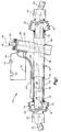
- FIG. 1 An example of a vehicle part 10 that can be tested in accordance with the present invention is shown in Figs. 1 and 2.
- the vehicle part 10 is a hydraulically-assisted rack and pinion steering gear of known construction.
- the steering gear 10 includes a housing 12, an elongate steering rack 14, and an input shaft 16.
- the rack 14 extends through a passage 18 in the housing 12, and projects horizontally outward from the housing 12 at opposite ends of the passage 18.
- a pair of bushings 20 at the opposite ends of the passage 18 support the rack 14 for longitudinal movement along an axis 21.
- a pair of boot seals 22 enclose the opposite ends of the passage 18.
- the input shaft 16 projects outward from the housing 12 through a seal 28, and is rotatable about another axis 29 in response to rotation of the vehicle steering wheel.
- the steering gear 10 operates to move the rack 14 longitudinally in response to rotation of the input shaft 16 about the axis 29.
- the steering gear 10 thus actuates the steering linkage to steer the vehicle wheels in response to rotation of the steering wheel.
- the steering gear 10 includes a pinion gear 30, a piston 32, and a hydraulic fluid control valve 34, each of which is contained in the housing 12.
- the pinion gear 30 is connected with the input shaft 16 by a torsion bar 36, and is supported for rotation about the axis 29 in meshing engagement with a row of rack teeth 38 on the rack 14.
- the piston 32 is fixed to the rack 14 within a tubular portion 40 of the housing 12 which functions as a power cylinder.
- a pair of seals 42 define opposite ends of a pair of variable volume hydraulic fluid chambers 44 and 46 which are located in the power cylinder 40 on opposite sides of the piston 32.
- the valve 34 communicates with the first chamber 44 in the power cylinder 40 through a first two-way flow line 60.
- the valve 34 further communicates with the second chamber 46 in the power cylinder 40 through a second two-way flow line 62.
- the valve 34 receives hydraulic fluid from a reservoir 70 and a pump 72 through a hydraulic fluid inlet line 74.
- a hydraulic fluid outlet line 76 exhausts hydraulic fluid from the valve 34 to the reservoir 70.
- the valve 34 operates in a known manner in response to rotation of the input shaft 16 with the vehicle steering wheel.
- the input shaft 16 rotates with the steering wheel in a first direction about the axis 29, it rotates slightly relative to the pinion gear 30.
- the torsion bar 36 flexes to permit such rotation of the input shaft 16 relative to the pinion gear 30.
- the valve 34 responds to the resulting rotational displacement by opening hydraulic fluid flow paths that extend through the valve 34 from the inlet line 74 to the first two-way flow line 60.
- the valve 34 simultaneously opens hydraulic fluid flow paths that extend through the valve 34 from the second two-way flow line 62 to the outlet line 76.
- valve 34 communicates the pump 72 with the first chamber 44 in the power cylinder 40 to pressurize the first chamber 44, and simultaneously communicates the second chamber 46 in the power cylinder 40 with the reservoir 70 to vent the second chamber 46.
- a resulting flow of hydraulic fluid from the pump 72, and a resulting hydraulic fluid pressure differential acting across the piston 32, cause the piston 32 and the rack 14 to move to the right, as viewed in Fig. 1, along the axis 21. This causes the steering linkage to steer the vehicle wheels in a first direction.
- the pinion gear 30 rotates in meshing engagement with the rack teeth 38.
- the pinion gear 30 thus rotates about the axis 29 relative to the input shaft 16 in a follow-up manner so as to cancel the rotational displacement between the pinion gear 30 and the input shaft 16.
- the valve 34 responds by closing the previously opened hydraulic fluid flow paths. This equalizes the hydraulic fluid pressures acting on the piston 32 in the first and second chambers 44 and 46 in the power cylinder 40, and causes the piston 32 and the rack 14 to stop moving along the axis 21.
- the input shaft 16 is rotated with the steering wheel in an opposite direction about the axis 29, and is again rotated slightly relative to the pinion gear 30 upon flexing of the torsion bar 36.
- the valve 34 responds by pressurizing the second chamber 46 and by simultaneously venting the first chamber 44.
- the piston 32 and the rack 14 then move axially to the left, as viewed in Fig. 1.
- a resulting follow-up rotation of the pinion gear 30 relative to the input shaft 16 causes the valve 34 again to equalize the hydraulic fluid pressures in the two chambers 44 and 46 in the power cylinder 40.
- the steering gear 10 thus steers the vehicle wheels in directions and amounts corresponding to the directions and amounts of rotation of the steering wheel and the input shaft 16.
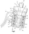
- the valve 34 includes a valve core 80 and a valve sleeve 82. Both the valve core 80 and the valve sleeve 82 have cylindrical shapes centered on the axis 29.
- the valve core 80 is defined by a section of the input shaft 16.
- the valve sleeve 82 is connected with an upper end portion 84 of the pinion gear 30 (Fig. 1). Accordingly, the valve sleeve 82 rotates relative to the valve core 80 when the pinion gear 30 rotates relative to the input shaft 16.
- a radially outer surface 86 of the valve core 80 has four recesses 88 at locations that are equally spaced from each other circumferentially about the axis 29.
- a radially inner surface 90 of the valve sleeve 82 has a plurality of similar recesses 92.
- a radially outer surface 94 of the valve sleeve 82 adjoins a surrounding cylindrical inner surface 96 of the housing 12.
- the outer surface 94 has a plurality of circumferentially extending grooves 98 and recesses 100.
- a corresponding plurality of ring seals 102 are received in the grooves 98 to seal the recesses 100 from each other.
- Several passages 104 one of which is shown in Fig.
- valve core 80 and the valve sleeve 82 together define the hydraulic fluid flow paths that extend through the valve 34 between the hydraulic lines 60, 62, 74 and 76.
- valve core 80 rotates relative to the valve sleeve 82.
- the recesses 88 at the outer surface 86 of the valve core 80 rotate relative to the recesses 92 at the inner surface 90 of the valve sleeve 82.
- the hydraulic fluid flow paths extending through the valve 34 between the hydraulic lines 60, 62, 74 and 76 are then adjusted so that certain flow paths become relatively restricted and certain flow paths become relatively unrestricted. Pressurized flows of hydraulic fluid are thereby directed through the valve 34 between the reservoir 70, the pump 72, and the chambers 44 and 46 in the power cylinder 40, as described above with reference to Fig. 1.
- the steering gear 10 is subject to functional deterioration through long term use in a vehicle. Such deterioration results from stress that is caused by the driving conditions experienced by the steering gear 10.
- the driving conditions include mechanical loads, thermal loads and environmental factors acting upon the steering gear 10.
- vibrations, the torsion of the steering input, the inertia of the steering linkage, and the pressure of the hydraulic fluid are mechanical loads that act upon the steering gear 10 during each steering maneuver.
- a particular aspect of the fluid pressure loading is the pressure surge that occurs at each start of the vehicle.
- Other mechanical loads include suspension loads that are transmitted to the steering gear 10 through the steering linkage at the opposite ends of the rack 14.
- Thermal loads result from both climatic conditions and the elevated temperatures attained by the hydraulic fluid as it is pressurized during steering maneuvers. Stress can also be caused by the impact of foreign objects such as gravel and the like.
- Other environmental factors that stress the steering gear 10 include the impingement of rain water, snow, mud and road salt.
- the present invention provides a method of forecasting the long term deterioration of the steering gear 10 that would result from long term wear at these and other locations in the steering gear 10.
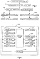
- the steering gear 200 is initially inspected by measuring preassembled and/or assembled parts of the steering gear 10 at a plurality of locations where wear is expected to occur. These locations preferably include each interface of relatively moving parts where a significant amount of wear is expected to contribute to functional deterioration of the steering gear 200. Several locations of this type are noted above. For example, the diameters of the cylindrical surfaces 94 and 96 (Fig. 2) could be measured prior to installation of the valve 34 in the housing 12.
- the steering gear 200 is installed in a test vehicle 206 which is equipped to monitor actual driving conditions, including loads and stress-inducing environmental factors, experienced by the steering gear 200 at the measured locations.
- the test vehicle 206 is equipped with a plurality of known sensors.
- a torque sensor 210 is connected with the input shaft 16 to monitor steering torque and/or steering wheel position.
- a pair of accelerometers 212 and 214 are connected with the steering gear 200 through the tie rods 24 or the ball joints 26 at the opposite ends of the rack 14.
- the accelerometers 212 and 214 measure vertical loads during jounce and rebound of the vehicle suspension. Loads attributable to operation of the hydraulic fluid pump 70 are monitored by meters such as an RPM meter 216, a flow meter 218, a pressure sensor 220 and a fluid temperature sensor 222. Loads caused by horizontal movement of the rack 14, and resulting compression and extension of the boot seals 22, are monitored by one or more position sensors 224.
- the test vehicle 206 is further equipped with a counter 226 for indicating the number and frequency of ignition key starts and stops. The resulting surges in the hydraulic fluid pressure are indicated accordingly.
- Other sensors include a temperature sensor 228 for monitoring the ambient temperature, and another counter 230 for monitoring wiper switch starts and stops.
- the counter 230 can indicate the impingement of water, mud, road salt and the like in terms of wiper use.
- the prototype steering gear 200 is subjected to a predetermined amount of long term use in the test vehicle 206.
- the predetermined amount of long term use preferably comprises, for example, at least approximately 100,000 driven miles. This amount of driving can be performed on a test track and/or on the road.
- a controller 242 (Fig. 4) periodically records driving conditions experienced by the steering gear 200 in terms of the output signals provided by the sensors 210-230 during the predetermined amount of long term use in the test vehicle 206.
- the recordings are made most extensively when the test vehicle 206 is being driven at or above the 90th percentile of "hard" driving. Those recordings indicate the driving conditions that are most stressful for the steering gear 200. Recordings are also made, although less extensively, when the test vehicle 206 is being driven under conditions that are less stressful for the steering gear 200.
- the controller 242 thus provides a real time recording of actual driving conditions.
- the steering gear 200 is removed from the test vehicle 206 upon completion of the driving step 240.
- the steering gear 200 is inspected by measuring it at the same locations where it was initially measured in the first step 202. The initial and subsequent measurements are compared to provide a wear profile comprising the individual amounts of wear, if any, that are found at the measured locations on the steering gear 200.
- the wear profile is recorded as a representation of the actual degree of deterioration of the steering gear 204 that was caused by the predetermined amount of long term use in the test vehicle 206.
- steps 248 and 250 also follow the driving step 240. These include a step 248 in which the actual driving conditions recorded by the controller 242 are analyzed. Specifically, parameters such as magnitude, frequency and duration of the various loads and environmental factors are compared so that relatively significant driving conditions can be distinguished from those that are relatively insignificant.
- the significant driving conditions are compiled from the real time recording of actual driving conditions. Specifically, the significant driving conditions are compiled to define an abridged schedule of corresponding test conditions that can be applied to a duplicate steering gear on a test stand. A schedule of test conditions is referred to in the art as a "block cycle.” The significant driving conditions are thus compiled to define a block cycle of corresponding test conditions.
- the steps shown in Fig. 3 can be repeated for a plurality of substantially identical prototype steering gears in one or more test vehicles.
- a recording step similar to the recording step 246 would record an average, mean, or other representative degree of actual deterioration for the prototype steering gears.
- a compiling step similar to the compiling step 250 would be applied to actual loads recorded for all of the prototype steering gears. This would yield a block cycle of test loads that is based on a more comprehensive sampling of actual driving conditions.
- a steering gear 260 which is substantially identical to the prototype steering gear 200.
- the steering gear 260 is a representative sample of a production run of steering gears that are substantially identical duplicates of the prototype steering gear 200.
- the sample steering gear 260 is initially inspected by measuring it at the same locations where the prototype steering gear 200 was measured in steps 202 and 244 shown in Fig. 3.
- the sample steering gear 260 is mounted on a test stand 266.
- the test stand 266 is equipped with actuating devices for applying stress-including test conditions to the sample steering gear 260.
- actuating devices for applying stress-including test conditions to the sample steering gear 260.
- These include a first mechanical actuator 268 for applying steering torque to the input shaft 16, and a pair of second mechanical actuators 270 and 272 for applying resistance to horizontal movement at opposite ends of the rack 14.
- the first mechanical actuator 268 preferably comprises an electric motor with an output shaft coupled to the input shaft 16, as known in the art.
- the second mechanical actuators 270 and 272 could comprise pneumatic or hydraulic motors coupled to corresponding end portions of the rack 14, also as known in the art.
- a known pump switch 274 actuates the corresponding pump 70.
- the test stand 266 comprises a known arrangement of actuating devices 268-274.
- actuating devices are conventionally operated to run a steering gear through repetitive back-and-forth movements of the input shaft 16 and the rack 14.
- the test stand 266 is further equipped with additional actuating devices that cooperate with the actuating devices 268-274 to run the sample steering gear 260 through the block cycle of stress-inducing test conditions described above.
- the additional actuating devices on the test stand 266 include a pair of third mechanical actuators 276 and 278, a heat source 280, and an environmental simulator 282.
- the third mechanical actuators 276 and 278 apply vertical loads at the opposite ends of the rack 14.
- the heat source 280 comprises a known apparatus for raising the ambient temperature to elevated levels.
- the environmental simulator 282 comprises a known apparatus for spraying water, salt water, or the like.
- the sample steering gear 260 is subjected to test conditions on the test stand 266. Specifically, the sample steering gear 260 is subjected to cumulative test conditions through repetitive applications of the block cycle of test conditions. This step is performed by operating a controller 286 (Fig. 6) with a program that comprises the block cycle of test conditions.
- the actual driving conditions experienced by the prototype steering gear 200 include mechanical loads, thermal loads, and environmental factors that occur both simultaneously and sequentially in the course of 100,000 driven miles.
- the deteriorating effects of the actual driving conditions may be greater when they are applied simultaneously rather than sequentially. Therefore, the test conditions in the block cycle include corresponding mechanical loads, thermal loads, and environmental factors that occur both simultaneously and sequentially in the block cycle. This helps to ensure that the deteriorating effects of the test conditions closely match the deteriorating effects of the corresponding actual conditions from which they were derived in the steps shown in Fig. 3.
- the block cycle of test conditions also includes starts and stops on the test stand 266 that correspond to starts and stops of the test vehicle 206. Specifically, the block cycle directs the controller 286 to operate the pump switch 274 on the test stand 266 with starts and stops corresponding to the ignition starts and stops monitored by the counter 226 (Fig. 4). This causes surges of hydraulic fluid pressure in the sample steering gear 260 that correspond to the surges of hydraulic fluid pressure in the prototype steering gear 200. The block cycle similarly directs the controller 286 to operate the environmental simulator 282 with starts and stops corresponding to the starts and stops of the wiper switch that are monitored by the other counter 230. This causes the environmental factors applied to the sample steering gear 260 to correspond with the environmental factors experienced by the prototype steering gear 200.
- the block cycle of test conditions is applied to the sample steering gear 260 throughout a large number of counted repetitions.
- the block cycle may be applied 100,000 times in step 284.
- the sample steering gear 260 is removed from the test stand 266, and is inspected by measuring it again at the same locations where it was initially measured in the first step 262.
- the initial and subsequent measurements of the sample steering gear 260 are compared to provide a wear profile comprising the individual amounts of wear that are found at the measured locations.
- the wear profile is recorded as a representation of the induced degree of deterioration experienced by the sample steering gear 260 on the test stand 266 upon application of a certain number of the block cycles.
- the induced degree of deterioration of the sample steering gear 260 is compared with the actual degree of deterioration of the prototype steering gear 200. If the induced degree of deterioration is substantially less than or greater than the actual degree of deterioration, then steps 262, 264, 284, 286, 288, 290 and 292 are repeated for another sample steering gear like the sample gear 260. However, a greater or lesser number of block cycles is applied to the other sample steering gear in step 284 in order to induce a correspondingly greater or lesser degree of deterioration. This process would continue until a sample steering gear is found to have an induced degree of deterioration that is substantially the same as the actual degree of deterioration.
- the next step 294 shown in Fig. 5 is to record the total number of times that the block cycle was applied in the final application of step 284.
- Step 294 thus identifies the total number of times that the block cycle must be applied on the test stand 266 in order to apply cumulative test conditions that induce substantially the same degree of deterioration that was caused by the actual driving conditions experienced in the test vehicle 266. Since that degree of deterioration was caused by actual driving conditions experienced throughout the entire course of 100,000 driven miles (in the present example), the total number of block cycles recorded in step 294 is correlated to 100,000 driven miles. It follows that subsequent application of the same number of the block cycles to a duplicate steering gear will simulate actual driving conditions experienced throughout the entire course of 100,000 driven miles. The amount of induced deterioration experienced by such a duplicate steering gear will thus forecast the amount of actual deterioration to be expected for other duplicate steering gears through actual use in vehicles driven 100,000 miles. This is indicated by the additional steps shown schematically in Fig. 7.
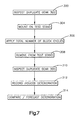
- the first step 300 shown in Fig. 7 applies to a duplicate steering gear 302 which is substantially identical to the sample steering gear 260 described above.
- the duplicate steering gear 302 is inspected by measuring it at the same locations where the sample steering gear 260 was measured in steps 262 and 288 shown in Fig. 5.
- the duplicate steering gear 302 is mounted on a test stand like the test stand 266 described above with reference to Fig. 4.
- the duplicate steering gear 302 is subjected to repeated applications of the block cycle of test conditions.
- the block cycle is applied to the duplicate steering gear 302 the total number of times recorded in step 294 of Fig. 5.
- the duplicate steering gear 302 is thus subjected to cumulative test conditions that simulate actual driving conditions previously experienced by the prototype steering gear 200 throughout 100,000 driven miles of long term use in the test vehicle 206.
- the duplicate steering gear 302 is removed from the test stand, and is inspected by measuring it again at the same locations where it was initially measured in the first step 300.
- the initial and subsequent measurements of the duplicate steering gear 302 are compared to provide a wear profile comprising the individual amounts of wear that are found at the measured locations.
- the wear profile is recorded as a representation of the induced degree of deterioration experienced by the duplicate steering gear 302 upon application of the predetermined number of the block cycles.
- the induced degree of deterioration of the duplicate steering gear 302 is compared with the actual degree of deterioration of the prototype steering gear 200. If the induced degree of deterioration does not exceed the actual degree of deterioration by more than a predetermined acceptable amount, then the duplicate steering gear 302 is found to have performed as well as the prototype steering gear 200 when subjected to stress-inducing conditions corresponding to 100,000 driven miles. Since other duplicate steering gears would be expected to have the same long-term reliability as the duplicate steering gear 302, it is then forecast that such other duplicate steering gears also will perform as well as the prototype steering gear 200 under actual driving conditions in vehicles driven 100,000 miles.
- the invention relates to a method comprising the steps of: applying cumulative test conditions to a vehicle part on a test stand by applying a block cycle of test conditions; and subsequently inspecting said vehicle part to determine an induced degree of deterioration.
Landscapes
- Physics & Mathematics (AREA)
- General Physics & Mathematics (AREA)
- Testing Of Devices, Machine Parts, Or Other Structures Thereof (AREA)
- Power Steering Mechanism (AREA)
- Testing Electric Properties And Detecting Electric Faults (AREA)
Applications Claiming Priority (2)
| Application Number | Priority Date | Filing Date | Title |
|---|---|---|---|
| US08/764,558 US5880381A (en) | 1996-12-12 | 1996-12-12 | Method of testing vehicle parts |
| US764558 | 1996-12-12 |
Publications (2)
| Publication Number | Publication Date |
|---|---|
| EP0848240A2 true EP0848240A2 (de) | 1998-06-17 |
| EP0848240A3 EP0848240A3 (de) | 1999-12-15 |
Family
ID=25071060
Family Applications (1)
| Application Number | Title | Priority Date | Filing Date |
|---|---|---|---|
| EP97121651A Withdrawn EP0848240A3 (de) | 1996-12-12 | 1997-12-09 | Verfahren zur Prüfung von Fahrzeugteilen |
Country Status (4)
| Country | Link |
|---|---|
| US (1) | US5880381A (de) |
| EP (1) | EP0848240A3 (de) |
| JP (1) | JP3170478B2 (de) |
| KR (1) | KR100287927B1 (de) |
Families Citing this family (8)
| Publication number | Priority date | Publication date | Assignee | Title |
|---|---|---|---|---|
| US20050061065A1 (en) * | 2003-09-23 | 2005-03-24 | Gilman Engineering & Manufacturing Co., Llc | Apparatus and method for function testing |
| US7912607B2 (en) * | 2005-01-06 | 2011-03-22 | Honda Motor Co., Ltd. | Method for crash testing a motor vehicle |
| US9574972B2 (en) * | 2011-01-05 | 2017-02-21 | GM Global Technology Operations LLC | Methods and systems for evaluating vehicle steering systems |
| US20140092252A1 (en) * | 2011-05-12 | 2014-04-03 | Magna Electronics Inc. | System and method for annotating video |
| US9365162B2 (en) | 2012-08-20 | 2016-06-14 | Magna Electronics Inc. | Method of obtaining data relating to a driver assistance system of a vehicle |
| US9683916B2 (en) | 2015-06-12 | 2017-06-20 | Ford Global Technologies, Llc | Rough road simulation |
| US10559138B2 (en) | 2015-12-18 | 2020-02-11 | Ge Global Sourcing Llc | Sensor signal processing system and method |
| KR102602685B1 (ko) * | 2023-06-05 | 2023-11-15 | 남혁모 | 차량의 선바이즈용 회전체 응력체크장치 |
Family Cites Families (11)
| Publication number | Priority date | Publication date | Assignee | Title |
|---|---|---|---|---|
| US3255628A (en) * | 1963-12-11 | 1966-06-14 | Gen Motors Corp | Rating gear designs |
| US3832894A (en) * | 1969-09-10 | 1974-09-03 | Autoscan Inc | Chassis dynamometer |
| JPS5433401A (en) * | 1977-08-16 | 1979-03-12 | Meidensha Electric Mfg Co Ltd | Method of driving equivaent road simulation system |
| US4499759A (en) * | 1980-12-05 | 1985-02-19 | The Budd Company | Road simulator testing automotive and truck wheels and hubs |
| US4501139A (en) * | 1983-08-26 | 1985-02-26 | Mts Systems Corporation | Test system for testing front wheel drive components of automobiles |
| US4672844A (en) * | 1986-03-26 | 1987-06-16 | Schenck Pegasus | Testing apparatus with improved follower mechanism |
| EP0329795B1 (de) * | 1987-09-11 | 1993-05-19 | Mitsubishi Denki Kabushiki Kaisha | Servolenkeinrichtung |
| US4931949A (en) * | 1988-03-21 | 1990-06-05 | Monitoring Technology Corporation | Method and apparatus for detecting gear defects |
| DE69106032T2 (de) * | 1990-04-23 | 1995-08-03 | Tanken Seiko Kk | Verfahren zur Vorhersage von Abweichungen in mechanischen Dichtungen und Gerät zu ihrer Vorhersage. |
| US5602450A (en) * | 1995-07-31 | 1997-02-11 | Chrysler Corporation | Apparatus for remotely operating an automobile ignition switch |
| US5610330A (en) * | 1996-01-16 | 1997-03-11 | Ford Motor Company | Effective road profile control method for a spindle-coupled road simulator |
-
1996
- 1996-12-12 US US08/764,558 patent/US5880381A/en not_active Expired - Fee Related
-
1997
- 1997-12-09 EP EP97121651A patent/EP0848240A3/de not_active Withdrawn
- 1997-12-10 KR KR1019970067280A patent/KR100287927B1/ko not_active Expired - Fee Related
- 1997-12-12 JP JP34293297A patent/JP3170478B2/ja not_active Expired - Fee Related
Also Published As
| Publication number | Publication date |
|---|---|
| KR100287927B1 (ko) | 2001-12-28 |
| KR19980063982A (ko) | 1998-10-07 |
| JP3170478B2 (ja) | 2001-05-28 |
| EP0848240A3 (de) | 1999-12-15 |
| US5880381A (en) | 1999-03-09 |
| JPH10206284A (ja) | 1998-08-07 |
Similar Documents
| Publication | Publication Date | Title |
|---|---|---|
| US5880381A (en) | Method of testing vehicle parts | |
| CN110542567B (zh) | 汽车传动系路面冲击载荷模拟方法 | |
| CA2555983C (en) | Mobile test rig for tyres, and implementation process for such a test rig | |
| JP4266818B2 (ja) | 操縦安定性の実時間評価用タイヤ試験機 | |
| JP5094747B2 (ja) | ストラットアセンブリの試験方法およびシステム | |
| CN102636357B (zh) | 电液伺服汽车转向系统试验台 | |
| JP7431145B2 (ja) | 自動車試験システム及び実路走行シミュレータ | |
| CN103487265A (zh) | 汽车动力转向系统研发和性能检测平台 | |
| US5652375A (en) | Apparatus, method and reusable model-structure for impact testing vehicle components | |
| CN112924198A (zh) | 一种用于汽车底盘模拟路试的加载系统及试验设备 | |
| CN113188791A (zh) | 密封圈模拟实际工况高低温压扭耐久试验机及试验方法 | |
| US6055853A (en) | Instrumented data acquisition system and steering wheel monitor for vehicle steering system | |
| CN108051193A (zh) | 一种车用电动撑杆机构动态负载模拟方法及试验装置 | |
| KR100301557B1 (ko) | 차량용 파워 스티어링 시스템의 부하 특성 시험 장치 | |
| CN2395845Y (zh) | 压力-位移式轴承压装机测控装置 | |
| CN104849029B (zh) | 一种遮阳板测试系统 | |
| CN214748854U (zh) | 密封圈模拟实际工况高低温压扭耐久试验机 | |
| RU2105964C1 (ru) | Стенд для испытания рулевого управления автомобиля | |
| CN116164892B (zh) | 一种驱动桥总成的漏油测试装置及方法 | |
| Data et al. | Identification of steering system parameters by experimental measurements processing | |
| CN114755032A (zh) | 一种前轴主销寿命试验装置及方法 | |
| US4457164A (en) | Testing of oil seals in power-assisted rack and pinion steering units | |
| Lund et al. | Approaches to vehicle dynamics and durability testing | |
| Harnett | Objective methods for the assessment of passenger car steering quality | |
| Ende et al. | Analysis of steering system elasticities and their impact on on-centre handling |
Legal Events
| Date | Code | Title | Description |
|---|---|---|---|
| PUAI | Public reference made under article 153(3) epc to a published international application that has entered the european phase |
Free format text: ORIGINAL CODE: 0009012 |
|
| AK | Designated contracting states |
Kind code of ref document: A2 Designated state(s): DE ES FR GB IT SE |
|
| AX | Request for extension of the european patent |
Free format text: AL;LT;LV;MK;RO;SI |
|
| PUAL | Search report despatched |
Free format text: ORIGINAL CODE: 0009013 |
|
| AK | Designated contracting states |
Kind code of ref document: A3 Designated state(s): AT BE CH DE DK ES FI FR GB GR IE IT LI LU MC NL PT SE |
|
| AX | Request for extension of the european patent |
Free format text: AL;LT;LV;MK;RO;SI |
|
| RIC1 | Information provided on ipc code assigned before grant |
Free format text: 6G 01M 13/00 A, 6G 01M 13/02 B, 6G 01M 17/06 B |
|
| 17P | Request for examination filed |
Effective date: 20000614 |
|
| AKX | Designation fees paid |
Free format text: DE ES FR GB IT SE |
|
| STAA | Information on the status of an ep patent application or granted ep patent |
Free format text: STATUS: THE APPLICATION HAS BEEN WITHDRAWN |
|
| 18W | Application withdrawn |
Withdrawal date: 20020213 |