EP0847851B1 - Apparatus and method for forming handles in plastic bags - Google Patents
Apparatus and method for forming handles in plastic bags Download PDFInfo
- Publication number
- EP0847851B1 EP0847851B1 EP97121775A EP97121775A EP0847851B1 EP 0847851 B1 EP0847851 B1 EP 0847851B1 EP 97121775 A EP97121775 A EP 97121775A EP 97121775 A EP97121775 A EP 97121775A EP 0847851 B1 EP0847851 B1 EP 0847851B1
- Authority
- EP
- European Patent Office
- Prior art keywords
- blade
- shaped
- base portion
- rotary
- plastic bags
- Prior art date
- Legal status (The legal status is an assumption and is not a legal conclusion. Google has not performed a legal analysis and makes no representation as to the accuracy of the status listed.)
- Expired - Lifetime
Links
Images





Classifications
-
- B—PERFORMING OPERATIONS; TRANSPORTING
- B26—HAND CUTTING TOOLS; CUTTING; SEVERING
- B26F—PERFORATING; PUNCHING; CUTTING-OUT; STAMPING-OUT; SEVERING BY MEANS OTHER THAN CUTTING
- B26F1/00—Perforating; Punching; Cutting-out; Stamping-out; Apparatus therefor
- B26F1/38—Cutting-out; Stamping-out
- B26F1/44—Cutters therefor; Dies therefor
-
- B—PERFORMING OPERATIONS; TRANSPORTING
- B26—HAND CUTTING TOOLS; CUTTING; SEVERING
- B26F—PERFORATING; PUNCHING; CUTTING-OUT; STAMPING-OUT; SEVERING BY MEANS OTHER THAN CUTTING
- B26F1/00—Perforating; Punching; Cutting-out; Stamping-out; Apparatus therefor
- B26F1/38—Cutting-out; Stamping-out
- B26F1/384—Cutting-out; Stamping-out using rotating drums
-
- B—PERFORMING OPERATIONS; TRANSPORTING
- B26—HAND CUTTING TOOLS; CUTTING; SEVERING
- B26F—PERFORATING; PUNCHING; CUTTING-OUT; STAMPING-OUT; SEVERING BY MEANS OTHER THAN CUTTING
- B26F1/00—Perforating; Punching; Cutting-out; Stamping-out; Apparatus therefor
- B26F1/38—Cutting-out; Stamping-out
- B26F1/44—Cutters therefor; Dies therefor
- B26F2001/4472—Cutting edge section features
-
- B—PERFORMING OPERATIONS; TRANSPORTING
- B26—HAND CUTTING TOOLS; CUTTING; SEVERING
- B26F—PERFORATING; PUNCHING; CUTTING-OUT; STAMPING-OUT; SEVERING BY MEANS OTHER THAN CUTTING
- B26F1/00—Perforating; Punching; Cutting-out; Stamping-out; Apparatus therefor
- B26F1/38—Cutting-out; Stamping-out
- B26F1/44—Cutters therefor; Dies therefor
- B26F2001/4481—Cutters therefor; Dies therefor having special lateral or edge outlines or special surface shapes, e.g. apertures
-
- B—PERFORMING OPERATIONS; TRANSPORTING
- B29—WORKING OF PLASTICS; WORKING OF SUBSTANCES IN A PLASTIC STATE IN GENERAL
- B29C—SHAPING OR JOINING OF PLASTICS; SHAPING OF MATERIAL IN A PLASTIC STATE, NOT OTHERWISE PROVIDED FOR; AFTER-TREATMENT OF THE SHAPED PRODUCTS, e.g. REPAIRING
- B29C2793/00—Shaping techniques involving a cutting or machining operation
- B29C2793/0045—Perforating
-
- B—PERFORMING OPERATIONS; TRANSPORTING
- B29—WORKING OF PLASTICS; WORKING OF SUBSTANCES IN A PLASTIC STATE IN GENERAL
- B29C—SHAPING OR JOINING OF PLASTICS; SHAPING OF MATERIAL IN A PLASTIC STATE, NOT OTHERWISE PROVIDED FOR; AFTER-TREATMENT OF THE SHAPED PRODUCTS, e.g. REPAIRING
- B29C66/00—General aspects of processes or apparatus for joining preformed parts
- B29C66/01—General aspects dealing with the joint area or with the area to be joined
- B29C66/05—Particular design of joint configurations
- B29C66/20—Particular design of joint configurations particular design of the joint lines, e.g. of the weld lines
- B29C66/23—Particular design of joint configurations particular design of the joint lines, e.g. of the weld lines said joint lines being multiple and parallel or being in the form of tessellations
- B29C66/232—Particular design of joint configurations particular design of the joint lines, e.g. of the weld lines said joint lines being multiple and parallel or being in the form of tessellations said joint lines being multiple and parallel, i.e. the joint being formed by several parallel joint lines
-
- B—PERFORMING OPERATIONS; TRANSPORTING
- B29—WORKING OF PLASTICS; WORKING OF SUBSTANCES IN A PLASTIC STATE IN GENERAL
- B29C—SHAPING OR JOINING OF PLASTICS; SHAPING OF MATERIAL IN A PLASTIC STATE, NOT OTHERWISE PROVIDED FOR; AFTER-TREATMENT OF THE SHAPED PRODUCTS, e.g. REPAIRING
- B29C66/00—General aspects of processes or apparatus for joining preformed parts
- B29C66/80—General aspects of machine operations or constructions and parts thereof
- B29C66/84—Specific machine types or machines suitable for specific applications
- B29C66/851—Bag or container making machines
- B29C66/8511—Bag making machines
-
- B—PERFORMING OPERATIONS; TRANSPORTING
- B31—MAKING ARTICLES OF PAPER, CARDBOARD OR MATERIAL WORKED IN A MANNER ANALOGOUS TO PAPER; WORKING PAPER, CARDBOARD OR MATERIAL WORKED IN A MANNER ANALOGOUS TO PAPER
- B31B—MAKING CONTAINERS OF PAPER, CARDBOARD OR MATERIAL WORKED IN A MANNER ANALOGOUS TO PAPER
- B31B70/00—Making flexible containers, e.g. envelopes or bags
- B31B70/74—Auxiliary operations
- B31B70/86—Forming integral handles or mounting separate handles
- B31B70/874—Forming integral handles or mounting separate handles involving punching or cutting
-
- Y—GENERAL TAGGING OF NEW TECHNOLOGICAL DEVELOPMENTS; GENERAL TAGGING OF CROSS-SECTIONAL TECHNOLOGIES SPANNING OVER SEVERAL SECTIONS OF THE IPC; TECHNICAL SUBJECTS COVERED BY FORMER USPC CROSS-REFERENCE ART COLLECTIONS [XRACs] AND DIGESTS
- Y10—TECHNICAL SUBJECTS COVERED BY FORMER USPC
- Y10S—TECHNICAL SUBJECTS COVERED BY FORMER USPC CROSS-REFERENCE ART COLLECTIONS [XRACs] AND DIGESTS
- Y10S383/00—Flexible bags
- Y10S383/903—Stress relief
-
- Y—GENERAL TAGGING OF NEW TECHNOLOGICAL DEVELOPMENTS; GENERAL TAGGING OF CROSS-SECTIONAL TECHNOLOGIES SPANNING OVER SEVERAL SECTIONS OF THE IPC; TECHNICAL SUBJECTS COVERED BY FORMER USPC CROSS-REFERENCE ART COLLECTIONS [XRACs] AND DIGESTS
- Y10—TECHNICAL SUBJECTS COVERED BY FORMER USPC
- Y10S—TECHNICAL SUBJECTS COVERED BY FORMER USPC CROSS-REFERENCE ART COLLECTIONS [XRACs] AND DIGESTS
- Y10S493/00—Manufacturing container or tube from paper; or other manufacturing from a sheet or web
- Y10S493/916—Pliable container
- Y10S493/926—Pliable container having handle or suspension means
-
- Y—GENERAL TAGGING OF NEW TECHNOLOGICAL DEVELOPMENTS; GENERAL TAGGING OF CROSS-SECTIONAL TECHNOLOGIES SPANNING OVER SEVERAL SECTIONS OF THE IPC; TECHNICAL SUBJECTS COVERED BY FORMER USPC CROSS-REFERENCE ART COLLECTIONS [XRACs] AND DIGESTS
- Y10—TECHNICAL SUBJECTS COVERED BY FORMER USPC
- Y10T—TECHNICAL SUBJECTS COVERED BY FORMER US CLASSIFICATION
- Y10T156/00—Adhesive bonding and miscellaneous chemical manufacture
- Y10T156/10—Methods of surface bonding and/or assembly therefor
- Y10T156/1002—Methods of surface bonding and/or assembly therefor with permanent bending or reshaping or surface deformation of self sustaining lamina
- Y10T156/1007—Running or continuous length work
- Y10T156/1015—Folding
-
- Y—GENERAL TAGGING OF NEW TECHNOLOGICAL DEVELOPMENTS; GENERAL TAGGING OF CROSS-SECTIONAL TECHNOLOGIES SPANNING OVER SEVERAL SECTIONS OF THE IPC; TECHNICAL SUBJECTS COVERED BY FORMER USPC CROSS-REFERENCE ART COLLECTIONS [XRACs] AND DIGESTS
- Y10—TECHNICAL SUBJECTS COVERED BY FORMER USPC
- Y10T—TECHNICAL SUBJECTS COVERED BY FORMER US CLASSIFICATION
- Y10T156/00—Adhesive bonding and miscellaneous chemical manufacture
- Y10T156/10—Methods of surface bonding and/or assembly therefor
- Y10T156/1052—Methods of surface bonding and/or assembly therefor with cutting, punching, tearing or severing
- Y10T156/1056—Perforating lamina
-
- Y—GENERAL TAGGING OF NEW TECHNOLOGICAL DEVELOPMENTS; GENERAL TAGGING OF CROSS-SECTIONAL TECHNOLOGIES SPANNING OVER SEVERAL SECTIONS OF THE IPC; TECHNICAL SUBJECTS COVERED BY FORMER USPC CROSS-REFERENCE ART COLLECTIONS [XRACs] AND DIGESTS
- Y10—TECHNICAL SUBJECTS COVERED BY FORMER USPC
- Y10T—TECHNICAL SUBJECTS COVERED BY FORMER US CLASSIFICATION
- Y10T156/00—Adhesive bonding and miscellaneous chemical manufacture
- Y10T156/10—Methods of surface bonding and/or assembly therefor
- Y10T156/1052—Methods of surface bonding and/or assembly therefor with cutting, punching, tearing or severing
- Y10T156/108—Flash, trim or excess removal
-
- Y—GENERAL TAGGING OF NEW TECHNOLOGICAL DEVELOPMENTS; GENERAL TAGGING OF CROSS-SECTIONAL TECHNOLOGIES SPANNING OVER SEVERAL SECTIONS OF THE IPC; TECHNICAL SUBJECTS COVERED BY FORMER USPC CROSS-REFERENCE ART COLLECTIONS [XRACs] AND DIGESTS
- Y10—TECHNICAL SUBJECTS COVERED BY FORMER USPC
- Y10T—TECHNICAL SUBJECTS COVERED BY FORMER US CLASSIFICATION
- Y10T156/00—Adhesive bonding and miscellaneous chemical manufacture
- Y10T156/10—Methods of surface bonding and/or assembly therefor
- Y10T156/1052—Methods of surface bonding and/or assembly therefor with cutting, punching, tearing or severing
- Y10T156/1084—Methods of surface bonding and/or assembly therefor with cutting, punching, tearing or severing of continuous or running length bonded web
-
- Y—GENERAL TAGGING OF NEW TECHNOLOGICAL DEVELOPMENTS; GENERAL TAGGING OF CROSS-SECTIONAL TECHNOLOGIES SPANNING OVER SEVERAL SECTIONS OF THE IPC; TECHNICAL SUBJECTS COVERED BY FORMER USPC CROSS-REFERENCE ART COLLECTIONS [XRACs] AND DIGESTS
- Y10—TECHNICAL SUBJECTS COVERED BY FORMER USPC
- Y10T—TECHNICAL SUBJECTS COVERED BY FORMER US CLASSIFICATION
- Y10T83/00—Cutting
- Y10T83/465—Cutting motion of tool has component in direction of moving work
- Y10T83/4766—Orbital motion of cutting blade
- Y10T83/4795—Rotary tool
- Y10T83/483—With cooperating rotary cutter or backup
- Y10T83/4838—With anvil backup
-
- Y—GENERAL TAGGING OF NEW TECHNOLOGICAL DEVELOPMENTS; GENERAL TAGGING OF CROSS-SECTIONAL TECHNOLOGIES SPANNING OVER SEVERAL SECTIONS OF THE IPC; TECHNICAL SUBJECTS COVERED BY FORMER USPC CROSS-REFERENCE ART COLLECTIONS [XRACs] AND DIGESTS
- Y10—TECHNICAL SUBJECTS COVERED BY FORMER USPC
- Y10T—TECHNICAL SUBJECTS COVERED BY FORMER US CLASSIFICATION
- Y10T83/00—Cutting
- Y10T83/788—Tool pair comprises rotatable anvil and fixed-type tool
-
- Y—GENERAL TAGGING OF NEW TECHNOLOGICAL DEVELOPMENTS; GENERAL TAGGING OF CROSS-SECTIONAL TECHNOLOGIES SPANNING OVER SEVERAL SECTIONS OF THE IPC; TECHNICAL SUBJECTS COVERED BY FORMER USPC CROSS-REFERENCE ART COLLECTIONS [XRACs] AND DIGESTS
- Y10—TECHNICAL SUBJECTS COVERED BY FORMER USPC
- Y10T—TECHNICAL SUBJECTS COVERED BY FORMER US CLASSIFICATION
- Y10T83/00—Cutting
- Y10T83/929—Tool or tool with support
- Y10T83/9309—Anvil
- Y10T83/9312—Rotatable type
Definitions
- the present invention relates generally to apparatus and methods for manufacturing plastic bags and, more particularly, relates to an apparatus and method utilizing a rotary cutting die having a generally W-shaped blade for forming the handles of a plastic bag.
- a collapsed tube of thermoplastic film is provided in a longitudinal/machine direction.
- the collapsed tube proceeds downstream to a heat sealing and perforation station, which forms pairs of closely-spaced, parallel transverse heat seals at bag-length distances apart and, in addition, forms transverse perforation lines between each of the pairs of transverse heat seals.
- the collapsed tube is in the form of a plurality of handleless bags (pillowcases) interconnected along the perforation lines.
- the interconnected handleless bags are optionally folded and then fed to a cutting station for the purpose of forming a pair of handles in each of the plastic bags.
- An example of one such cutting station includes a rotary anvil and a rotary cutting die mounted parallel and adjacent to each other.
- the rotary cutting die includes a cylindrical shaft and a blade mounted to the shaft.
- the speed limitation in the cutting process pertains to the blade design of the rotary cutting die.
- a blade design that only cuts in the machine direction i.e. direction of bag movement
- a blade design that cuts in both the longitudinal direction and transverse direction has a speed limitation directly related to practical blade life.
- the formation of plastic bags with handles requires a blade design that cuts in both the longitudinal direction and transverse direction.
- the blade of the rotary cutting die has traditionally been shaped in the form of a U as shown in FIG. 8.
- the U-shaped blade creates an incision having a corresponding shape.
- the legs of the U are along the handles of the bag and the base portion of the U is along the mouth of the bag.
- the direction of the cut is from the bottom of the U to the top of the U, or vice versa.
- the blade of the rotary cutting die interferes with the adjacent rotary anvil.
- This interference can be measured as a force.
- the interference/contact force changes in relation to an area of the blade contacting the rotary anvil at a given time. The greater the area of the blade contacting the rotary anvil at a given time, the greater the interference force.
- the interference force must be sufficiently high throughout the entire cutting process to allow the blade to render a complete incision (i.e. cut fully through the plastic material of the bag). The interference force is at a maximum when the greatest area of the blade is contacting the rotary anvil.
- FIG. 8 schematically illustrates a U-shaped blade alongside a graph showing the variation in interference force between the blade and an adjacent rotary anvil.
- the machine direction is represented in FIG. 8 by an arrow labeled L
- the transverse direction is represented by an arrow labeled T.
- the interference force at a certain moment in time is directly proportional to the area of the blade contacting the rotary anvil.
- the area of the blade contacting the rotary anvil at a certain moment in time may be approximated by the area of intersection of a transverse line and the blade in FIG. 8.
- U-shaped blade design in FIG. 8 Another drawback of the U-shaped blade design in FIG. 8 is that it shortens the effective life of the rotary anvil.
- the legs of the U-shaped blade are perpendicular to the base portion, thereby causing a groove in the adjacent rotary anvil as the cutting process progresses.
- a further drawback of the prior art blade design depicted in FIGS. 9 and 13 is that the plastic bag produced thereby is susceptible to tearing in the handle region.
- the handles are stressed in a manner represented by the stress lines 80 in FIG. 13. These stress lines originate from the upper ends of the handles and diverge as they travel downward through the handles.
- the stress lines are such that the outermost ones 80a and 80b thereof are not confined to the handles, but rather leave the handles temporarily at points 82 and 84 before re-entering the handles near the lowermost ends thereof.
- This phenomenon of the outermost stress lines not being confined to the handles makes the handles somewhat susceptible to tearing along tear lines 86, which extend between the points 82 and 84.
- an apparatus is used to form specially-configured handles in a plurality of interconnected plastic bags travelling in a longitudinal direction.
- the plastic bags are interconnected along transverse lines of weakness spaced at bag-length distances apart.
- the apparatus comprises a rotary anvil and a rotary cutting die.
- the rotary anvil has a first axis of rotation.
- the rotary cutting die is disposed adjacent to the rotary anvil and has a second axis of rotation substantially parallel to the first axis of rotation.
- the rotary cutting die includes a rotatable cylindrical shaft, a blade shell mounted on the shaft, and a generally W-shaped blade formed on the blade shell.
- the blade has a base portion and a pair of opposing legs. The opposing legs extend upwardly relative to the base portion and outwardly relative to each other. The blade cuts and thereby forms a pair of handles in each of the plastic bags in response to passing the plastic bags between the rotary anvil and the rotary cutting die.
- a method utilizes the foregoing rotary anvil and rotary cutting die to form the handles in a plurality of interconnected plastic bags.
- FIG. 1 depicts a system and process sequence for forming a plurality of interconnected plastic bags.
- a tube 10 of thermoplastic film is provided to the system in a longitudinal direction L.
- the film is preferably composed of high-density polyethylene, low-density polyethylene, linear low-density polyethylene, or blends of the foregoing.
- the thickness of the film may range from about 100,16 ⁇ m (4 mils) to about 50,8 ⁇ m (2 mils) depending on the composition of the material used to form the bags and the intended use of the bags.
- the collapsed tube 10 proceeds downstream to a heat sealing and perforation station 14.
- the heat sealing and perforation station 14 forms pairs of closely-spaced, parallel transverse heat seals 16a and 16b at bag-length distances apart.
- One of the heat seals 16a and 16b forms the sealed bottom of one bag, while the other of the heat seals 16a and 16b insures that bag handles formed downstream from the station 14 are properly sealed at their upper ends.
- the hear seal 16b forms the sealed bottom, while the heat seal 16a forms the sealed upper ends of the handles.
- the station 14 forms transverse lines of weakness 18 between each of the pairs of transverse heat seals 16a and 16b such that the collapsed tube 10 includes a plurality of handleless bags (pillowcases) interconnected along the transverse lines of weakness 18.
- the transverse lines of weakness 18 may be in the form of perforation lines or lines of reduced thickness.
- the heat-sealed and perforated tube 10 proceeds downstream to a first folding station 20, which inwardly folds opposing side sections 22a and 22b of the tube 10.
- the tube 10 includes the pair of opposing side sections 22a and 22b and a central section 24 extending between the side sections 22a and 22b.
- the side section 22a is folded inward approximately 180 degrees relative to the central section 24, and, similarly, the side section 22b is folded inward approximately 180 degrees relative to the central section 24.
- the portion of the tube 10 including the folded side sections 22a and 22b and the underlying portions of the central section 24 is comprised of four layers of plastic material, while the portion of the tube 10 between the folded side sections 22a and 22b is comprised of two layers of plastic material.
- the once-folded tube 10 then proceeds downstream to a cutting station 26, which forms a pair of handles in each of the interconnected bags of the tube 10.
- the construction of the cutting station 26 is described in detail below with reference to FIGS. 2-5.
- the cutting station 26 is comprised of a rotary anvil 28 and a rotary cutting die 30.
- the rotary anvil 28 has a first axis A 1 of rotation
- the rotary cutting die 30 has a second axis A 2 of rotation parallel to the first axis of rotation A 1 .
- the rotary anvil 28 rotates in a clockwise direction about the first axis A 1 of rotation
- the rotary cutting die 30 rotates in a counter clockwise direction about the second axis A 2 of rotation.
- the rotary cutting die 30 is disposed adjacent to the rotary anvil 28 and includes a rotatable cylindrical shaft 32, a blade shell 34 mounted on the shaft 32, and a generally W-shaped blade 36 formed on the blade shell 34.
- the shaft 32, the blade shell 34, and the blade 36 are preferably composed of hard steel.
- the blade shell 34 and the blade 36 are preferably composed of a grade D2 cold work tool steel.
- the blade shell 34 may be mounted to the shaft 32 by conventional fastening means such as screws, bolts, or the like. As best shown in FIG. 3, the blade shell 34 extends approximately 180 degrees about the shaft 32 such that the blade shell 34 only partially encompasses the shaft 32.
- the W-shaped blade 36 is integrally formed with the blade shell 34 by machining away an outer portion of the blade shell 34 until only the blade 36 remains.
- the W-shaped blade 36 is formed by four linear segments 40a, 38a, 38b, and 40b connected directly to each other in the foregoing sequence.
- the segments 38a and 38b form a base portion of the blade 36, while the segments 40a and 40b form a pair of opposing legs of the blade 36.
- the base portion 38a-b is shaped in the form of an inverted "V".
- the opposing legs 40a-b extend upwardly relative to the base portion 38a-b and outwardly relative to each other.
- the legs 40a' and 40b' of the rounded W-shaped blade 36' are connected to the respective segments 38a' and 38b' of the base portion by the respective curved transition segments 42 and 44.
- the blade 36 has a cross-section including a trapezoidally-shaped upper portion 46 and a rectangularly-shaped lower portion 48.
- the upper end of the upper portion 46 is sufficiently narrow to allow the blade 36 to completely cut through the plastic bags as they pass between the rotary anvil 28 and the rotary cutting die 30 depicted in FIGS. 2 and 3.
- the anvil 28 has a radius R 1 , of approximately 63,5 mm (2.50 inches); the shaft 32 of the rotary cutting die 30 has a radius R 2 of approximately 38,1 mm (1.50 inches); and the blade shell has a radius R 3 of approximately 57,15 mm (2.25 inches).
- the blade 36 has a height H of approximately 6,35 mm (0.25 inches).
- the rectangularly-shaped lower portion 48 of the blade 36 has a width W 1 of approximately 6,35 mm (0.25 inches), and the upper end of the trapezoidally-shaped upper portion 46 of the blade 36 has a width W 2 of approximately 50,8 ⁇ m (0.002 inches).
- the width W 2 may be varied in accordance with the desired sharpness of the blade 36.
- the slopes of the angled surfaces of the upper portion 46 may be varied such that the inclusive angle ⁇ is in range between about 30 degrees and about 90 degrees.
- the cutting station 26 cuts each of the plastic bags as they pass between the rotary anvil 28 and the rotary cutting die 30.
- the radii of the rotary anvil 28 and the rotary cutting die 30 are selected such that a single rotation of these elements corresponds to movement of the collapsed tube 10 in the longitudinal direction L for a single bag-length distance.
- the cutting station 26 is longitudinally positioned such that the blade 36 cuts a W-shaped incision 50 in each of the plastic bags in the illustrated position.
- the W-shaped incision 50 extends completely through the material of the associated plastic bag.
- the legs of the W-shaped incision 50 are located along the respective folded side sections 22a and 22b and the respective underlying portions of the central section 24.
- Most of the base portion of the W-shaped incision 50 is located along the central section 24 between the folded side sections 22a and 22b.
- the opposing ends of the base portion of the W-shaped incision 50 intersect the respective folded side sections 22a and 22b and the respective underlying portions of the central section 24.
- the legs of the W-shaped incision 50 cross the heat seal 16a and intersect the line of weakness 18 at two corresponding points of intersection.
- each plastic bag proceeds downstream to a punching station 52 that punches out the W-shaped cutout section encompassed by the W-shaped incision 50 and the line of weakness 18.
- the punching station 52 may employ a reciprocating mechanical element or a cyclically-operated pneumatic element. Removing the cutout section of each plastic bag provides the bag with a pair of handles 54 and 56 that are more readily apparent in the unfolded plastic bag schematically shown in FIG. 10.
- the line of weakness 18 is preferably created by the heat sealing and perforation station 14 such that the line of weakness 18 is substantially weaker between the two points at which the incision 50 intersects the line of weakness 18 than outside these two points of intersection.
- the processed plastic tube 10 proceeds downstream from the punching station 52 to a second folding station 58, which inwardly folds the opposing side sections 22a and 22b a second time along with the respective underlying portions of the central section 24.
- the twice-folded tube 10 is comprised of six layers of plastic material.
- a predetermined number of the interconnected plastic bags may be wound in a roll and placed into a suitable package.
- the interconnected plastic bags may proceed to a combination of differential speed rollers that separates the bags along the perforation lines 18 into isolated plastic bags.
- a predetermined number of the isolated plastic bags may then be interleaved, wound into a roll, and placed into a suitable package, or may be stacked and placed into a suitable package.
- An isolated plastic bag 60 formed by the process in FIG. 1 is schematically depicted in FIG. 10.
- the plastic bag 60 includes the pair of handles 54 and 56 formed by the W-shaped incision. Fold lines imparted by the first and second folding stations 20 and 58 are designated by the reference numerals 62 and 64, respectively.
- a significant advantage of the W-shaped blade design of the rotary cutting die 30 is that, relative to the prior art blade designs in FIGS. 8 and 9, it reduces the difference between the maximum and minimum interference force between the blade 36 and the rotary anvil 28 during a single cutting cycle of the blade 36.
- FIG. 6 schematically illustrates the W-shaped blade 36 alongside a graph showing the variation in interference force between the blade 36 and the adjacent rotary anvil 28.
- the rounded W-shaped blade design in FIG. 7 significantly reduces the difference between the maximum and minimum interference force between the blade 36' and the rotary anvil 28 during a single cutting cycle of the blade 36'.
- the maximum interference force associated with the rounded W-shaped blade design is approximately 136,08 kg (300 pounds), which is still significantly less than the peak interference forces associated with the prior art blade designs in FIGS. 8 and 9. If the amount of contact between the blade 36 and the adjacent rotary anvil 28 at a given time is defined as the contact area, the maximum interference force of approximately 136,08 kg (300 pounds) translates to a ratio of the maximum-to-maximum contact area that is no greater than about 25:1.
- the W-shaped blade design extends the life of the rotary anvil 28.
- the legs of the U-shaped blade are perpendicular to the base portion, thereby causing a groove in the adjacent rotary anvil as the cutting process progresses.
- the legs of the W-shaped blade 36 are slanted away from each other.
- contact between the legs and the adjacent rotating anvil 28 is not narrowly confined to a groove. Rather, the legs of the W-shaped blade 36 distribute their contact to a wider surface area on the rotating anvil 28.
- the life of the anvil 28 is extended by a magnitude proportional to the angle at which the legs of the blade 36 are slanted away from each other.
- a further advantage of the W-shaped blade design is that the plastic bags formed by that design are less susceptible to tearing in the handle region than the plastic bags formed by the prior art blade design depicted in FIGS. 9 and 13.
- the handles are stressed in a manner represented by the stress lines 70.
- These stress lines originate from the upper ends of the handles and diverge as they travel downward through the handles.
- the stress lines are such that the outermost ones 70a and 70b thereof are strictly confined to the handles. Such confinement of the stress lines to the handles minimizes the possibility of a tear developing in the handle region.
- the outermost stess lines 80a and 80b of the plastic bag formed by the prior art blade design in FIG. 13 are not confined to the handles, thereby making the handles more susceptible to tearing along tear lines 86.
Landscapes
- Life Sciences & Earth Sciences (AREA)
- Forests & Forestry (AREA)
- Engineering & Computer Science (AREA)
- Mechanical Engineering (AREA)
- Making Paper Articles (AREA)
- Perforating, Stamping-Out Or Severing By Means Other Than Cutting (AREA)
Description
- The present invention relates generally to apparatus and methods for manufacturing plastic bags and, more particularly, relates to an apparatus and method utilizing a rotary cutting die having a generally W-shaped blade for forming the handles of a plastic bag.
- In one common method for manufacturing plastic bags, a collapsed tube of thermoplastic film is provided in a longitudinal/machine direction. The collapsed tube proceeds downstream to a heat sealing and perforation station, which forms pairs of closely-spaced, parallel transverse heat seals at bag-length distances apart and, in addition, forms transverse perforation lines between each of the pairs of transverse heat seals. After leaving the heat sealing and perforation station, the collapsed tube is in the form of a plurality of handleless bags (pillowcases) interconnected along the perforation lines. The interconnected handleless bags are optionally folded and then fed to a cutting station for the purpose of forming a pair of handles in each of the plastic bags.
- An example of one such cutting station includes a rotary anvil and a rotary cutting die mounted parallel and adjacent to each other. The rotary cutting die includes a cylindrical shaft and a blade mounted to the shaft. As each of the interconnected handleless bags pass between the rotary anvil and the rotary cutting die, the blade of the rotating cutting die contacts and cuts through the plastic material of each bag, thereby creating an incision in the bag.
- One of the major components of cost in manufacturing plastic bags is the lower production speed associated with the aforementioned cutting station. The speed limitation in the cutting process pertains to the blade design of the rotary cutting die. A blade design that only cuts in the machine direction (i.e. direction of bag movement) has no speed limitations, while a blade design that cuts in both the longitudinal direction and transverse direction has a speed limitation directly related to practical blade life. The formation of plastic bags with handles requires a blade design that cuts in both the longitudinal direction and transverse direction.
- Heretofore, the blade of the rotary cutting die has traditionally been shaped in the form of a U as shown in FIG. 8. The U-shaped blade creates an incision having a corresponding shape. When the incision is U-shaped, the legs of the U are along the handles of the bag and the base portion of the U is along the mouth of the bag. In the rotary die cutting process performed at the cutting station, the direction of the cut is from the bottom of the U to the top of the U, or vice versa.
- During the cutting process, the blade of the rotary cutting die interferes with the adjacent rotary anvil. This interference can be measured as a force. During a single rotational cycle of the blade, the interference/contact force changes in relation to an area of the blade contacting the rotary anvil at a given time. The greater the area of the blade contacting the rotary anvil at a given time, the greater the interference force. The interference force must be sufficiently high throughout the entire cutting process to allow the blade to render a complete incision (i.e. cut fully through the plastic material of the bag). The interference force is at a maximum when the greatest area of the blade is contacting the rotary anvil.
- A drawback of the prior art U-shaped blade design is that the difference between the maximum and minimum interference force during a single cutting cycle of the blade is quite large. This difference is depicted in FIG. 8, which schematically illustrates a U-shaped blade alongside a graph showing the variation in interference force between the blade and an adjacent rotary anvil. The machine direction is represented in FIG. 8 by an arrow labeled L, while the transverse direction is represented by an arrow labeled T. As a plastic bag travels in the machine direction L between the rotary anvil and the blade of the rotary cutting die, the interference force at a certain moment in time is directly proportional to the area of the blade contacting the rotary anvil. The area of the blade contacting the rotary anvil at a certain moment in time may be approximated by the area of intersection of a transverse line and the blade in FIG. 8.
- While the blade is forming the base portion of the U-shaped incision, the area of the blade contacting the rotary anvil increases to a large peak and, therefore, the interference force increases to a peak of approximately 1632,93 kg (3600 pounds). This maximum interference force is required in order for the blade to render a complete incision. In contrast, while the blade is forming the legs of the U-shaped incision, the area of the blade contacting the rotary anvil at a certain moment in time is quite small and, therefore, the interference force is close to zero kilograms (pounds). Like the U-shaped blade design, another prior art blade design schematically illustrated in FIG. 9 suffers from a large difference between the maximum interference force (approximately 544,31 kg (1200 pounds)) and the minimum interference force (close to zero kilograms (pounds)).
- Unfortunately, in the prior art blade designs in FIGS. 8 and 9, parts of the blade of the rotary cutting die cannot effectively withstand the maximum interference force and are therefore worn down and eventually destroyed. This phenomenon sets specific limits on the practical processing speeds, particularly in the manufacture of handled plastic bags.
- Another drawback of the U-shaped blade design in FIG. 8 is that it shortens the effective life of the rotary anvil. The legs of the U-shaped blade are perpendicular to the base portion, thereby causing a groove in the adjacent rotary anvil as the cutting process progresses.
- A further drawback of the prior art blade design depicted in FIGS. 9 and 13 is that the plastic bag produced thereby is susceptible to tearing in the handle region. When the plastic bag is loaded with a product and then carried by its handles, the handles are stressed in a manner represented by the
stress lines 80 in FIG. 13. These stress lines originate from the upper ends of the handles and diverge as they travel downward through the handles. The stress lines are such that the outermost ones 80a and 80b thereof are not confined to the handles, but rather leave the handles temporarily at points 82 and 84 before re-entering the handles near the lowermost ends thereof. This phenomenon of the outermost stress lines not being confined to the handles makes the handles somewhat susceptible to tearing alongtear lines 86, which extend between the points 82 and 84. - A need therefore exists for an apparatus and method for forming handles in plastic bags which employs a blade design that reduces the difference between the maximum and minimum interference force between the blade and rotary anvil, that extends the effective life of the rotary anvil, and that renders the plastic bag produced thereby less susceptible to tearing in the handle region.
- To overcome the above mentioned drawbacks an apparatus according to Claim 1 and a method according to Claim 9 are provided. In accordance with one aspect of the present invention, an apparatus is used to form specially-configured handles in a plurality of interconnected plastic bags travelling in a longitudinal direction. The plastic bags are interconnected along transverse lines of weakness spaced at bag-length distances apart. The apparatus comprises a rotary anvil and a rotary cutting die. The rotary anvil has a first axis of rotation. The rotary cutting die is disposed adjacent to the rotary anvil and has a second axis of rotation substantially parallel to the first axis of rotation. The rotary cutting die includes a rotatable cylindrical shaft, a blade shell mounted on the shaft, and a generally W-shaped blade formed on the blade shell. The blade has a base portion and a pair of opposing legs. The opposing legs extend upwardly relative to the base portion and outwardly relative to each other. The blade cuts and thereby forms a pair of handles in each of the plastic bags in response to passing the plastic bags between the rotary anvil and the rotary cutting die.
- In accordance with another aspect of the present invention, a method utilizes the foregoing rotary anvil and rotary cutting die to form the handles in a plurality of interconnected plastic bags.
- Other objects and advantages of the invention will become apparent upon reading the following detailed description and upon reference to the drawings in which:
- FIG. 1 is a plan view, in schematic form, of a system for forming a plurality of interconnected plastic bags:
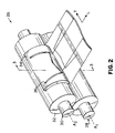
- FIG. 2 is an isometric view of an apparatus employed in the system in FIG. 1 and used for forming a pair of handles in each of the plastic bags;
- FIG. 3 is a section taken generally along line 3-3 in FIG. 2;
- FIG. 4 is an enlarged plan view of a blade of a rotary die of the apparatus in FIG. 2;
- FIG. 5 is a section taken generally along line 5-5 in FIG. 4;
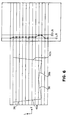
- FIG. 6 is a schematic view of a W-shaped blade alongside a graph showing the variation in interference force between the blade and an adjacent rotary anvil;
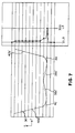
- FIG. 7 is a schematic view of a rounded W-shaped blade alongside a graph showing the variation in interference force between the blade and an adjacent rotary anvil;
- FIG. 8 is a schematic view of a prior art blade alongside a graph showing the variation in interference force between the blade and an adjacent rotary anvil;
- FIG. 9 is a schematic view of another prior art blade alongside a graph showing the variation in interference force between the blade and an adjacent rotary anvil;
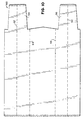
- FIG. 10 is a plan view, in schematic form, of a plastic bag manufactured by the system in FIG. 1;
- FIG. 11 is a plan view, in schematic form, of the handle region of the plastic bag in FIG. 10 showing stress lines passing through one of the handles;
- FIG. 12 is a plan view, in schematic form, of the handle region of a plastic bag made with the rounded W-shaped blade in FIG. 7 and showing stress lines passing through one of the handles; and
- FIG. 13 is a plan view, in schematic form, of the handle region of a prior art plastic bag made with the prior art blade in FIG. 9 and showing stress lines passing through one of the handles.
-
- While the invention is susceptible to various modifications and alternative forms, a specific embodiment thereof has been shown by way of example in the drawings and will herein be described in detail. It should be understood, however, that it is not intended to limit the invention to the particular forms disclosed, but on the contrary, the intention is to cover all modifications, equivalents, and alternatives falling within the scope of the invention as defined by the appended claims.
- Turning now to the drawings, FIG. 1 depicts a system and process sequence for forming a plurality of interconnected plastic bags. A
tube 10 of thermoplastic film is provided to the system in a longitudinal direction L. The film is preferably composed of high-density polyethylene, low-density polyethylene, linear low-density polyethylene, or blends of the foregoing. The thickness of the film may range from about 100,16 µm (4 mils) to about 50,8 µm (2 mils) depending on the composition of the material used to form the bags and the intended use of the bags. - Alter collapsing the
tube 10 at a collapsingstation 12, thecollapsed tube 10 proceeds downstream to a heat sealing andperforation station 14. The heat sealing andperforation station 14 forms pairs of closely-spaced, paralleltransverse heat seals station 14 are properly sealed at their upper ends. In the illustrated embodiment, the hearseal 16b forms the sealed bottom, while theheat seal 16a forms the sealed upper ends of the handles. - Simultaneously with the heat sealing or after forming the heat seals 16a and 16b, the
station 14 forms transverse lines ofweakness 18 between each of the pairs oftransverse heat seals collapsed tube 10 includes a plurality of handleless bags (pillowcases) interconnected along the transverse lines ofweakness 18. The transverse lines ofweakness 18 may be in the form of perforation lines or lines of reduced thickness. - Next, the heat-sealed and
perforated tube 10 proceeds downstream to afirst folding station 20, which inwardly folds opposing side sections 22a and 22b of thetube 10. Thetube 10 includes the pair of opposing side sections 22a and 22b and acentral section 24 extending between the side sections 22a and 22b. The side section 22a is folded inward approximately 180 degrees relative to thecentral section 24, and, similarly, the side section 22b is folded inward approximately 180 degrees relative to thecentral section 24. As best shown in FIG. 2, the portion of thetube 10 including the folded side sections 22a and 22b and the underlying portions of thecentral section 24 is comprised of four layers of plastic material, while the portion of thetube 10 between the folded side sections 22a and 22b is comprised of two layers of plastic material. - The once-folded
tube 10 then proceeds downstream to a cuttingstation 26, which forms a pair of handles in each of the interconnected bags of thetube 10. The construction of the cuttingstation 26 is described in detail below with reference to FIGS. 2-5. - Referring first to FIGS. 2 and 3, the cutting
station 26 is comprised of arotary anvil 28 and a rotary cutting die 30. Therotary anvil 28 has a first axis A1 of rotation, while the rotary cutting die 30 has a second axis A2 of rotation parallel to the first axis of rotation A1. As indicated by the arrows in FIG. 3, therotary anvil 28 rotates in a clockwise direction about the first axis A1 of rotation, while the rotary cutting die 30 rotates in a counter clockwise direction about the second axis A2 of rotation. The rotary cutting die 30 is disposed adjacent to therotary anvil 28 and includes a rotatablecylindrical shaft 32, ablade shell 34 mounted on theshaft 32, and a generally W-shapedblade 36 formed on theblade shell 34. Theshaft 32, theblade shell 34, and theblade 36 are preferably composed of hard steel. Theblade shell 34 and theblade 36, in particular, are preferably composed of a grade D2 cold work tool steel. - The
blade shell 34 may be mounted to theshaft 32 by conventional fastening means such as screws, bolts, or the like. As best shown in FIG. 3, theblade shell 34 extends approximately 180 degrees about theshaft 32 such that theblade shell 34 only partially encompasses theshaft 32. The W-shapedblade 36 is integrally formed with theblade shell 34 by machining away an outer portion of theblade shell 34 until only theblade 36 remains. - Referring to FIG. 4, the W-shaped
blade 36 is formed by fourlinear segments segments blade 36, while thesegments blade 36. Thebase portion 38a-b is shaped in the form of an inverted "V". The opposinglegs 40a-b extend upwardly relative to thebase portion 38a-b and outwardly relative to each other. In an alternative embodiment shown schematically in FIG. 7, thelegs 40a' and 40b' of the rounded W-shaped blade 36' are connected to therespective segments 38a' and 38b' of the base portion by the respectivecurved transition segments - Referring to FIG. 5, the
blade 36 has a cross-section including a trapezoidally-shapedupper portion 46 and a rectangularly-shapedlower portion 48. The upper end of theupper portion 46 is sufficiently narrow to allow theblade 36 to completely cut through the plastic bags as they pass between therotary anvil 28 and the rotary cutting die 30 depicted in FIGS. 2 and 3. - Although the dimension of the various elements of the cutting
station 26 can be varied, these elements have the following dimensions in the preferred embodiment. Referring to FIG. 3, theanvil 28 has a radius R1, of approximately 63,5 mm (2.50 inches); theshaft 32 of the rotary cutting die 30 has a radius R2 of approximately 38,1 mm (1.50 inches); and the blade shell has a radius R3 of approximately 57,15 mm (2.25 inches). Referring to FIG. 5, theblade 36 has a height H of approximately 6,35 mm (0.25 inches). The rectangularly-shapedlower portion 48 of theblade 36 has a width W1 of approximately 6,35 mm (0.25 inches), and the upper end of the trapezoidally-shapedupper portion 46 of theblade 36 has a width W2 of approximately 50,8 µm (0.002 inches). The width W2 may be varied in accordance with the desired sharpness of theblade 36. The slopes of the angled surfaces of theupper portion 46 may be varied such that the inclusive angle α is in range between about 30 degrees and about 90 degrees. - Referring back to FIG. 1, the cutting
station 26 cuts each of the plastic bags as they pass between therotary anvil 28 and the rotary cutting die 30. The radii of therotary anvil 28 and the rotary cutting die 30 are selected such that a single rotation of these elements corresponds to movement of the collapsedtube 10 in the longitudinal direction L for a single bag-length distance. Also, the cuttingstation 26 is longitudinally positioned such that theblade 36 cuts a W-shapedincision 50 in each of the plastic bags in the illustrated position. - More specifically, the W-shaped
incision 50 extends completely through the material of the associated plastic bag. The legs of the W-shapedincision 50 are located along the respective folded side sections 22a and 22b and the respective underlying portions of thecentral section 24. Most of the base portion of the W-shapedincision 50 is located along thecentral section 24 between the folded side sections 22a and 22b. The opposing ends of the base portion of the W-shapedincision 50 intersect the respective folded side sections 22a and 22b and the respective underlying portions of thecentral section 24. The legs of the W-shapedincision 50 cross theheat seal 16a and intersect the line ofweakness 18 at two corresponding points of intersection. - After the cutting
station 26 forms the W-shapedincision 50 in each of the plastic bags, each plastic bag proceeds downstream to a punchingstation 52 that punches out the W-shaped cutout section encompassed by the W-shapedincision 50 and the line ofweakness 18. To punch out the cutout section, the punchingstation 52 may employ a reciprocating mechanical element or a cyclically-operated pneumatic element. Removing the cutout section of each plastic bag provides the bag with a pair ofhandles incision 50 and the line ofweakness 18, the line ofweakness 18 is preferably created by the heat sealing andperforation station 14 such that the line ofweakness 18 is substantially weaker between the two points at which theincision 50 intersects the line ofweakness 18 than outside these two points of intersection. - The processed
plastic tube 10 proceeds downstream from the punchingstation 52 to asecond folding station 58, which inwardly folds the opposing side sections 22a and 22b a second time along with the respective underlying portions of thecentral section 24. The twice-foldedtube 10 is comprised of six layers of plastic material. - To package the interconnected plastic bags formed by the process depicted in FIG. 1, a predetermined number of the interconnected plastic bags may be wound in a roll and placed into a suitable package. Alternatively, the interconnected plastic bags may proceed to a combination of differential speed rollers that separates the bags along the perforation lines 18 into isolated plastic bags. A predetermined number of the isolated plastic bags may then be interleaved, wound into a roll, and placed into a suitable package, or may be stacked and placed into a suitable package. An isolated
plastic bag 60 formed by the process in FIG. 1 is schematically depicted in FIG. 10. Theplastic bag 60 includes the pair ofhandles second folding stations reference numerals - Referring back to FIG. 2, a significant advantage of the W-shaped blade design of the rotary cutting die 30 is that, relative to the prior art blade designs in FIGS. 8 and 9, it reduces the difference between the maximum and minimum interference force between the
blade 36 and therotary anvil 28 during a single cutting cycle of theblade 36. This difference is depicted in FIG. 6, which schematically illustrates the W-shapedblade 36 alongside a graph showing the variation in interference force between theblade 36 and the adjacentrotary anvil 28. As a plastic bag travels in the machine direction L between theblade 36 and therotary anvil 28, the interference force remains close to zero because, at any given moment in time, only a small area of theblade 36 is contacting therotary anvil 28. Even while thebase portion 38a-b of theblade 36 is contacting therotary anvil 28, the area of theblade 36 contacting therotary anvil 28 at any given moment in time remains quite small. The interference force never increases above approximately 22,68 kg (50 pounds), which is significantly smaller than the peak interference forces associated with the prior art blade designs in FIGS. 8 and 9. The significant reduction in the maximum interference relative to the prior art blade designs allows theblade 36 to effectively withstand the maximum interference force, thereby minimizing wear on theblade 36 and providing less constraints on the processing speeds of the system in FIG. 1. - Like the W-shaped blade design in FIG. 6, the rounded W-shaped blade design in FIG. 7 significantly reduces the difference between the maximum and minimum interference force between the blade 36' and the
rotary anvil 28 during a single cutting cycle of the blade 36'. The maximum interference force associated with the rounded W-shaped blade design is approximately 136,08 kg (300 pounds), which is still significantly less than the peak interference forces associated with the prior art blade designs in FIGS. 8 and 9. If the amount of contact between theblade 36 and the adjacentrotary anvil 28 at a given time is defined as the contact area, the maximum interference force of approximately 136,08 kg (300 pounds) translates to a ratio of the maximum-to-maximum contact area that is no greater than about 25:1. - Another significant advantage of the W-shaped blade design is that it extends the life of the
rotary anvil 28. As stated above, in the prior art U-shaped blade design, the legs of the U-shaped blade are perpendicular to the base portion, thereby causing a groove in the adjacent rotary anvil as the cutting process progresses. In contrast, the legs of the W-shapedblade 36 are slanted away from each other. As a result, contact between the legs and the adjacentrotating anvil 28 is not narrowly confined to a groove. Rather, the legs of the W-shapedblade 36 distribute their contact to a wider surface area on the rotatinganvil 28. The life of theanvil 28 is extended by a magnitude proportional to the angle at which the legs of theblade 36 are slanted away from each other. - A further advantage of the W-shaped blade design is that the plastic bags formed by that design are less susceptible to tearing in the handle region than the plastic bags formed by the prior art blade design depicted in FIGS. 9 and 13. Referring to FIGS. 11 and 12, when the plastic bag formed by either the straight W-shaped design (FIG. 11) or the rounded W-shaped blade design (FIG. 12) is loaded with a product and then carried by its handles, the handles are stressed in a manner represented by the stress lines 70. These stress lines originate from the upper ends of the handles and diverge as they travel downward through the handles. The stress lines are such that the
outermost ones 70a and 70b thereof are strictly confined to the handles. Such confinement of the stress lines to the handles minimizes the possibility of a tear developing in the handle region. In contrast, as stated previously, the outermost stess lines 80a and 80b of the plastic bag formed by the prior art blade design in FIG. 13 are not confined to the handles, thereby making the handles more susceptible to tearing along tear lines 86. - While the present invention has been described with reference to one or more particular embodiments, those skilled in the art will recognize that many changes may be made thereto without departing from the scope of the present invention. Each of these embodiments and obvious variations thereof is contemplated as falling within the scope of the claimed invention, which is set forth in the following claims.
Claims (21)
- An apparatus for forming handles in a plurality of interconnected plastic bags traveling in a longitudinal direction, said plastic bags being interconnected along transverse lines of weakness spaced at bag-length distances apart, said apparatus comprising:a rotary anvil (28) having a first axis (A1) of rotation; anda rotary cutting die (30) disposed adjacent to said rotary anvil and having a second axis (A2) of rotation substantially parallel to said first axis of rotation, said rotary cutting die (30) including a rotatable cylindrical shaft (32) and a generally W-shaped blade (36) mounted to said shaft, said blade having a base portion (38a, 38b) and a pair of opposing legs (40a, 40b), said base portion having an inverted, V-shaped configuration, said opposing legs extending upwardly relative to said base portion and outwardly relative to each other, said opposing legs being coupled to said base portion, said blade cutting and thereby forming a pair of handles in each of said plastic bags in response to passing said plastic bags between said rotary anvil and said rotary cutting die.
- The apparatus of Claim 1, wherein said generally W-shaped blade (36) is formed on a blade shell (34) and said blade shell is mounted on said shaft (32).
- The apparatus of Claim 2, wherein a cross-section of said blade includes a trapezoidally-shaped upper portion and rectangularly-shaped lower portion.
- The apparatus of Claim 2, wherein an amount of contact between said blade and said rotary anvil at a given time is defined as contact area, said contact area varying between a minimum and a maximum as the pair of handles are formed on said one of said plastic bags, a ratio of said maximum contact area to said minimum contact area being no greater than about 25:1.
- The apparatus of Claim 2, wherein an interference force between said rotary cutting die and said rotary anvil is no greater than about 136,08 kg (300 pounds).
- The apparatus of Claim 2, wherein said opposing legs are coupled to said base portion via respective curved transition portions.
- The apparatus of Claim 2, wherein said opposing legs are coupled to said base portion via respective sharp transition portions.
- The apparatus of Claim 1, wherein the pair of opposing legs are linear.
- A method of forming plastic bags, comprising the steps of:providing a collapsed tube of thermoplastic film travelling in a longitudinal direction;forming pairs of closely-spaced, parallel transverse heat seals at bag-length distances apart;forming transverse lines of weakness between each of said pairs of transverse heat seals such as said collapsed tube includes a plurality of handleless bags interconnected along said transverse lines of weakness; andpassing each of said handleless plastic bags between a rotary anvil (28) and a rotary cutting die to form a pair of handles in each of said bags, said rotary anvil having a first axis of rotation, said rotary cutting die disposed adjacent to said rotary anvil (28) and having a second axis of rotation substantially parallel to said first axis of rotation, said rotary cutting die (30) including a rotatable cylindrical shaft (32) and a generally W-shaped blade (36) mounted to said shaft, said blade having a base portion and a pair of substantially linear opposing legs, said base portion having an inverted V-shaped configuration, said opposing legs extending upwardly relative to said base portion and outwardly relative to each other, said opposing legs being coupled to said base portion via transition portions, said blade creating a generally W-shaped incision in each of said handieless bags.
- The method of Claim 9, wherein said general W-shaped blade (36) is formed on a blade shell (34) and said blade shell is mounted on said shaft (32).
- The method of Claim 10, wherein said lines of weakness are lines of perforations.
- The method of claim 11, wherein said W-shaped incision includes opposing legs intersecting said line of weakness in each of said bags at two points of intersection.
- The method in claim 10, wherein said line of weakness is weaker between said two points of intersection than outside two points of intersection.
- The method of claim 10, wherein said collapsed tube of thermoplastic film includes a pair of opposing side sections and a central section extending between said side sections, and further including the step of folding said side sections inward prior to said step of passing each of said handleless plastic bags between said rotary anvil and said rotary cutting die, said blade cutting through inner portions of said respective folded side sections and a generally W-shaped portion of said central section.
- The method of Claim 10, wherein a cross-section of said blade includes a trapezoidally-shaped upper portion and rectangularly-shaped lower portion.
- The method of claim 10, wherein said base portion has an inverted, generally V-shaped configuration.
- The method of Claim 10, wherein an amount of contact between said blade and said rotary anvil at a given time is defined as contact area, said contact area varying between a minimum and a maximum as the pair of handles are formed on said one of said plastic bags, a ratio of said maximum contact area to said minimum contact area being no greater than about 25:1.
- The method of Claim 10, wherein an interference force between said rotary cutting die and said rotary anvil is no greater than about 136,08 kg (300 pounds).
- The method of Claim 10, wherein said opposing legs are coupled to said base portion via respective curved transition portions.
- The method of Claim 10, wherein said opposing legs are coupled to said base portion via respective sharp transition portions.
- The method of Claim 10, wherein the pair of opposing legs are linear.
Applications Claiming Priority (2)
| Application Number | Priority Date | Filing Date | Title |
|---|---|---|---|
| US08/763,741 US5935367A (en) | 1996-12-11 | 1996-12-11 | Apparatus and method for forming handles in plastic bags |
| US763741 | 1996-12-11 |
Publications (3)
| Publication Number | Publication Date |
|---|---|
| EP0847851A2 EP0847851A2 (en) | 1998-06-17 |
| EP0847851A3 EP0847851A3 (en) | 1999-11-03 |
| EP0847851B1 true EP0847851B1 (en) | 2002-10-16 |
Family
ID=25068696
Family Applications (1)
| Application Number | Title | Priority Date | Filing Date |
|---|---|---|---|
| EP97121775A Expired - Lifetime EP0847851B1 (en) | 1996-12-11 | 1997-12-10 | Apparatus and method for forming handles in plastic bags |
Country Status (3)
| Country | Link |
|---|---|
| US (1) | US5935367A (en) |
| EP (1) | EP0847851B1 (en) |
| DE (1) | DE69716390T2 (en) |
Families Citing this family (31)
| Publication number | Priority date | Publication date | Assignee | Title |
|---|---|---|---|---|
| DK173884B1 (en) * | 1998-10-19 | 2002-01-28 | Roll O Matic As | Method and apparatus for making a foil web with transverse weld seams and cuts |
| SE515960C2 (en) * | 2000-03-16 | 2001-11-05 | Fas Converting Machinery Ab | Process and machine for machining an elongated web of material |
| US20020187694A1 (en) * | 2001-06-11 | 2002-12-12 | Brighton Thomas B. | Mesh reinforced breathable plastic film |
| US20030044481A1 (en) * | 2001-08-28 | 2003-03-06 | Beaudry Wallace J. | Cast ceramic edge or embossed surface for a cutting die |
| DK174943B1 (en) * | 2002-02-13 | 2004-03-15 | Inter Ikea Sys Bv | Machine for punching items from a sheet of corrugated cardboard and for forming bending guide lines in the blanks |
| SE528041C2 (en) * | 2004-07-02 | 2006-08-15 | Sandvik Intellectual Property | Rotary knife and rotary knife unit with such a rotary knife |
| SE527838C2 (en) * | 2004-07-02 | 2006-06-20 | Sandvik Intellectual Property | A rotary knife and a rotary knife device provided with such a rotary knife |
| TW200821125A (en) * | 2006-08-23 | 2008-05-16 | Sulzer Chemtech Ag | A metering device |
| US9944487B2 (en) | 2007-02-21 | 2018-04-17 | Curt G. Joa, Inc. | Single transfer insert placement method and apparatus |
| US9550306B2 (en) | 2007-02-21 | 2017-01-24 | Curt G. Joa, Inc. | Single transfer insert placement and apparatus with cross-direction insert placement control |
| TWI455809B (en) * | 2009-03-31 | 2014-10-11 | Chan Li Machinery Co Ltd | Packaging film opening crack line opening knife module |
| US9089453B2 (en) | 2009-12-30 | 2015-07-28 | Curt G. Joa, Inc. | Method for producing absorbent article with stretch film side panel and application of intermittent discrete components of an absorbent article |
| US8656817B2 (en) * | 2011-03-09 | 2014-02-25 | Curt G. Joa | Multi-profile die cutting assembly |
| PL2628472T3 (en) | 2012-02-20 | 2016-07-29 | Joa Curt G Inc | Method of forming bonds between discrete components of disposable articles |
| US9908739B2 (en) | 2012-04-24 | 2018-03-06 | Curt G. Joa, Inc. | Apparatus and method for applying parallel flared elastics to disposable products and disposable products containing parallel flared elastics |
| EP2849936B1 (en) * | 2012-05-14 | 2018-10-31 | Tetra Laval Holdings & Finance SA | Arrangement in a creasing machine, and products obtained therefrom |
| CN104057494A (en) * | 2013-03-23 | 2014-09-24 | 何星宇 | Plum blossom pattern press knife |
| US9283683B2 (en) | 2013-07-24 | 2016-03-15 | Curt G. Joa, Inc. | Ventilated vacuum commutation structures |
| USD703711S1 (en) | 2013-08-23 | 2014-04-29 | Curt G. Joa, Inc. | Ventilated vacuum communication structure |
| USD703712S1 (en) | 2013-08-23 | 2014-04-29 | Curt G. Joa, Inc. | Ventilated vacuum commutation structure |
| USD703248S1 (en) | 2013-08-23 | 2014-04-22 | Curt G. Joa, Inc. | Ventilated vacuum commutation structure |
| USD704237S1 (en) | 2013-08-23 | 2014-05-06 | Curt G. Joa, Inc. | Ventilated vacuum commutation structure |
| USD703247S1 (en) | 2013-08-23 | 2014-04-22 | Curt G. Joa, Inc. | Ventilated vacuum commutation structure |
| US9289329B1 (en) | 2013-12-05 | 2016-03-22 | Curt G. Joa, Inc. | Method for producing pant type diapers |
| CN103737648A (en) * | 2014-01-08 | 2014-04-23 | 浙江诺比德机械科技有限公司 | Elastic ribbon cutting device |
| ES2909332T3 (en) | 2015-07-24 | 2022-05-06 | Joa Curt G Inc | Vacuum Switching Apparatus and Procedures |
| US10717558B2 (en) * | 2016-10-17 | 2020-07-21 | Morrisette Paper Company, Inc. | Machine and process for packaging unique items |
| PT3787858T (en) | 2018-05-02 | 2022-08-23 | Roll O Matic As | A cutting apparatus for manufacturing bags utilizing a rotary cutting die |
| CN109532109B (en) * | 2018-11-28 | 2020-08-14 | 安徽省徽腾智能交通科技有限公司 | Plastic bag trompil and clout recovery plant |
| CN109334107B (en) * | 2018-11-28 | 2020-08-14 | 安徽省徽腾智能交通科技有限公司 | Working method of plastic bag hole opening and excess material recycling equipment |
| US11737930B2 (en) | 2020-02-27 | 2023-08-29 | Curt G. Joa, Inc. | Configurable single transfer insert placement method and apparatus |
Family Cites Families (44)
| Publication number | Priority date | Publication date | Assignee | Title |
|---|---|---|---|---|
| GB1044313A (en) * | 1963-10-18 | 1966-09-28 | Thomas Ballantyne Clerk | Rotary die cutting apparatus |
| US4326664A (en) * | 1979-03-15 | 1982-04-27 | Mobil Oil Corporation | Thermoplastic bags having stress relief feature at handle connection |
| US4367841A (en) * | 1980-11-18 | 1983-01-11 | Mobil Oil Corporation | Thermoplastic carrying bag with binary polyolefin resin blend |
| US4346834A (en) * | 1980-11-18 | 1982-08-31 | Mobil Oil Corporation | Thermoplastic carrying bag with polyolefin resin blend |
| US4464157A (en) * | 1981-10-05 | 1984-08-07 | Mobil Oil Corporation | Method of preparing a thermoplastic bag having reinforced handles |
| US4517873A (en) * | 1983-04-25 | 1985-05-21 | Wilson Manufacturing Company | Die cutting apparatus |
| US4493419A (en) * | 1983-11-03 | 1985-01-15 | Mobil Oil Corporation | Thermoplastic bag and bag pack |
| US4476979A (en) * | 1983-11-03 | 1984-10-16 | Mobil Oil Corporation | Thermoplastic bag pack |
| US4588392A (en) * | 1984-02-29 | 1986-05-13 | Mobil Oil Corporation | Method of forming a thermoplastic film sack having a stress relieved bottom gusset seal line |
| US4613988A (en) * | 1984-02-29 | 1986-09-23 | Mobil Oil Corporation | Thermoplastic bag and method of forming the same |
| US4571235A (en) * | 1984-05-02 | 1986-02-18 | Mobil Oil Corporation | Methods for preparing flat-bottom thermoplastic sack and systems therefore |
| US4816104A (en) * | 1984-05-02 | 1989-03-28 | Mobil Oil Corporation | Methods and systems for preparing flat-bottom thermoplastic sack |
| US4554192A (en) * | 1984-05-02 | 1985-11-19 | Mobil Oil Corporation | Thermoplastic bag and thermoplastic bag pack |
| US5149201A (en) * | 1984-05-02 | 1992-09-22 | Benoit Gordon L | Angle sealed bottom grocery sack |
| US4560067A (en) * | 1984-07-25 | 1985-12-24 | Mobil Oil Corporation | Thermoplastic bag pack |
| US4652253A (en) * | 1984-08-20 | 1987-03-24 | Mobil Oil Corporation | Method for preparing flat-bottom thermoplastic sack |
| US4604927A (en) * | 1984-10-09 | 1986-08-12 | Mobil Oil Corporation | Razor blade cutter assembly |
| US4790437A (en) * | 1984-11-26 | 1988-12-13 | Mobil Oil Corporation | Thermoplastic bag, bag pack and method of making the same |
| US4819806A (en) * | 1984-11-19 | 1989-04-11 | Mobil Oil Corporation | Thermoplastic bag, bag pack and method of making the same |
| US4840610A (en) * | 1984-11-26 | 1989-06-20 | Mobil Oil Corporation | Thermoplastic bag, bag pack and method of making the same |
| USD297113S (en) | 1985-04-08 | 1988-08-09 | Mobil Oil Corporation | Bag |
| US4655737A (en) * | 1985-04-24 | 1987-04-07 | Mobil Oil Corporation | Method for preparing flat-bottom thermoplastic sack |
| US4720872A (en) * | 1985-05-28 | 1988-01-19 | Mobil Oil Corporation | Thermoplastic bag and method of forming the same |
| US4804564A (en) * | 1985-09-03 | 1989-02-14 | Mobil Oil Corporation | Plastic bags of blends of linear ethylene polymers and aromatic polymers |
| US4656900A (en) * | 1985-11-15 | 1987-04-14 | Mobil Oil Corporation | Rotary tube punching arrangement and method for punching holes into a moving web material |
| US4744200A (en) * | 1986-10-30 | 1988-05-17 | Mobil Oil Corporation | Thermoplastic bag pack with single tab suspension |
| US4785938A (en) * | 1986-10-30 | 1988-11-22 | Mobil Oil Corporation | Thermoplastic bag pack |
| US4982637A (en) * | 1987-04-14 | 1991-01-08 | Mobil Oil Corporation | Rotary cutting apparatus |
| US4883450A (en) * | 1987-11-02 | 1989-11-28 | Mobil Oil Corp. | Process for making single side free plastic bag |
| US4812055A (en) * | 1987-12-29 | 1989-03-14 | Mobil Oil Corporation | Thermoplastic bag and method of forming the same |
| US4783856A (en) * | 1988-01-19 | 1988-11-15 | Mobil Oil Corporation | Disposable rain garment |
| US4911560A (en) * | 1988-04-08 | 1990-03-27 | Sonoco Products Company | Easy open bag |
| US5087234A (en) * | 1990-03-19 | 1992-02-11 | Mobil Oil Corporation | Method of forming an easy-open bag pack |
| US5219220A (en) * | 1992-05-04 | 1993-06-15 | Mobil Oil Corporation | Four-film diagonal gusset seals for bags |
| US5333730A (en) * | 1993-03-31 | 1994-08-02 | Mobil Oil Corporation | Bag pack and system for suspending and dispensing bags |
| US5507713A (en) * | 1993-09-09 | 1996-04-16 | Tenneco Plastics, Inc. | Easy-open bag pack, method of forming and system |
| US5573489A (en) * | 1993-12-22 | 1996-11-12 | Tenneco Plastics Company | Integral handled layflat thermoplastic bag |
| JP2693113B2 (en) * | 1994-04-08 | 1997-12-24 | 福岡丸本株式会社 | Shopping bag |
| US5611627A (en) * | 1995-02-23 | 1997-03-18 | Tenneco Packaging | Easy open thermoplastic bag |
| US5683340A (en) * | 1995-02-23 | 1997-11-04 | Tenneco Plastics Company | Method of making easy open thermoplastic bag |
| JPH08257994A (en) * | 1995-03-29 | 1996-10-08 | Tokyo Pack Seiki Kk | Device for punching grip hole in handle of portable paper bag |
| MX9700686A (en) * | 1995-05-31 | 1997-04-30 | Tenneco Plastics Co | Ostomy appliance and wound drainage device. |
| US5826475A (en) * | 1996-01-26 | 1998-10-27 | Kimberly-Clark Worldwide, Inc. | Knife shaft assembly |
| US5709641A (en) * | 1996-03-26 | 1998-01-20 | Tenneco Packaging Inc. | Thermoplastic bag structure |
-
1996
- 1996-12-11 US US08/763,741 patent/US5935367A/en not_active Expired - Fee Related
-
1997
- 1997-12-10 DE DE69716390T patent/DE69716390T2/en not_active Expired - Fee Related
- 1997-12-10 EP EP97121775A patent/EP0847851B1/en not_active Expired - Lifetime
Also Published As
| Publication number | Publication date |
|---|---|
| EP0847851A2 (en) | 1998-06-17 |
| EP0847851A3 (en) | 1999-11-03 |
| US5935367A (en) | 1999-08-10 |
| DE69716390D1 (en) | 2002-11-21 |
| DE69716390T2 (en) | 2003-03-06 |
Similar Documents
| Publication | Publication Date | Title |
|---|---|---|
| US5935367A (en) | Apparatus and method for forming handles in plastic bags | |
| US6688080B2 (en) | Method for manufacturing flexible packages having slide closures | |
| US6829873B2 (en) | Apparatus for manufacturing flexible packages having slide closures | |
| US4781474A (en) | Pouch with loop handle attached by oval seal | |
| US4931031A (en) | Method for improved container internal raw edge protection | |
| US6120183A (en) | Container and method of manufacturing same from a web of flexible material | |
| US8122687B2 (en) | Method of making flexible packages having slide closures | |
| US6820393B2 (en) | Apparatus for manufacturing flexible packages having slide closures | |
| US4722437A (en) | Package alignment system | |
| US6089753A (en) | Easy to open handle bag and method of making the same | |
| JPWO2016199863A1 (en) | Bag making machine and method for manufacturing plastic bags | |
| US3016806A (en) | Art of producing multiple compartment bags | |
| JP7122044B2 (en) | Bag-making method and bag-making machine | |
| EP0762974B1 (en) | Method of manufacturing double-chambered infusion bags by folding | |
| EP1731437A1 (en) | Gussetted plastic bag | |
| WO1998018674A1 (en) | A method for forming bags in plastic material and the bag thus produced | |
| JP2002254533A (en) | Packaging bag with gore and method and apparatus for manufacturing the same | |
| NL194435C (en) | Device for forming folding lines in raised bag bottoms in the manufacture of cross-bottom bags. | |
| EP1348535A2 (en) | Apparatus for manufacturing and filling flexible packages having slide fasteners | |
| EP0545970B1 (en) | Method of manufacturing filter bags and a filter bag | |
| US6023917A (en) | Method of producing finned packages, and a separating device for carrying out the method | |
| EP1510461A1 (en) | Tubular bagging machine | |
| NL8001858A (en) | REINFORCED BAG WITH INTEGRATED SECTION AND METHOD FOR MANUFACTURING THAT. | |
| CA1053953A (en) | Rectangular and flat bottom bag and method of manufacture | |
| US3528333A (en) | Die cutter |
Legal Events
| Date | Code | Title | Description |
|---|---|---|---|
| PUAI | Public reference made under article 153(3) epc to a published international application that has entered the european phase |
Free format text: ORIGINAL CODE: 0009012 |
|
| AK | Designated contracting states |
Kind code of ref document: A2 Designated state(s): DE IT |
|
| AX | Request for extension of the european patent |
Free format text: AL;LT;LV;MK;RO;SI |
|
| PUAL | Search report despatched |
Free format text: ORIGINAL CODE: 0009013 |
|
| AK | Designated contracting states |
Kind code of ref document: A3 Designated state(s): AT BE CH DE DK ES FI FR GB GR IE IT LI LU MC NL PT SE |
|
| AX | Request for extension of the european patent |
Free format text: AL;LT;LV;MK;RO;SI |
|
| 17P | Request for examination filed |
Effective date: 20000329 |
|
| AKX | Designation fees paid |
Free format text: DE IT |
|
| 17Q | First examination report despatched |
Effective date: 20001120 |
|
| GRAG | Despatch of communication of intention to grant |
Free format text: ORIGINAL CODE: EPIDOS AGRA |
|
| RAP1 | Party data changed (applicant data changed or rights of an application transferred) |
Owner name: PACTIV CORPORATION |
|
| GRAG | Despatch of communication of intention to grant |
Free format text: ORIGINAL CODE: EPIDOS AGRA |
|
| GRAG | Despatch of communication of intention to grant |
Free format text: ORIGINAL CODE: EPIDOS AGRA |
|
| GRAH | Despatch of communication of intention to grant a patent |
Free format text: ORIGINAL CODE: EPIDOS IGRA |
|
| GRAH | Despatch of communication of intention to grant a patent |
Free format text: ORIGINAL CODE: EPIDOS IGRA |
|
| GRAA | (expected) grant |
Free format text: ORIGINAL CODE: 0009210 |
|
| AK | Designated contracting states |
Kind code of ref document: B1 Designated state(s): DE IT |
|
| REF | Corresponds to: |
Ref document number: 69716390 Country of ref document: DE Date of ref document: 20021121 |
|
| PLBE | No opposition filed within time limit |
Free format text: ORIGINAL CODE: 0009261 |
|
| STAA | Information on the status of an ep patent application or granted ep patent |
Free format text: STATUS: NO OPPOSITION FILED WITHIN TIME LIMIT |
|
| 26N | No opposition filed |
Effective date: 20030717 |
|
| PGFP | Annual fee paid to national office [announced via postgrant information from national office to epo] |
Ref country code: DE Payment date: 20060105 Year of fee payment: 9 |
|
| PGFP | Annual fee paid to national office [announced via postgrant information from national office to epo] |
Ref country code: IT Payment date: 20061231 Year of fee payment: 10 |
|
| PG25 | Lapsed in a contracting state [announced via postgrant information from national office to epo] |
Ref country code: DE Free format text: LAPSE BECAUSE OF NON-PAYMENT OF DUE FEES Effective date: 20070703 |
|
| PG25 | Lapsed in a contracting state [announced via postgrant information from national office to epo] |
Ref country code: IT Free format text: LAPSE BECAUSE OF NON-PAYMENT OF DUE FEES Effective date: 20071210 |