EP0846920B1 - Mât d'injection de combustible pour un statoréacteur refroidi par perspiration - Google Patents
Mât d'injection de combustible pour un statoréacteur refroidi par perspiration Download PDFInfo
- Publication number
- EP0846920B1 EP0846920B1 EP97402899A EP97402899A EP0846920B1 EP 0846920 B1 EP0846920 B1 EP 0846920B1 EP 97402899 A EP97402899 A EP 97402899A EP 97402899 A EP97402899 A EP 97402899A EP 0846920 B1 EP0846920 B1 EP 0846920B1
- Authority
- EP
- European Patent Office
- Prior art keywords
- injection
- fuel
- leading edge
- stem
- strut
- Prior art date
- Legal status (The legal status is an assumption and is not a legal conclusion. Google has not performed a legal analysis and makes no representation as to the accuracy of the status listed.)
- Expired - Lifetime
Links
Images
Classifications
-
- F—MECHANICAL ENGINEERING; LIGHTING; HEATING; WEAPONS; BLASTING
- F23—COMBUSTION APPARATUS; COMBUSTION PROCESSES
- F23R—GENERATING COMBUSTION PRODUCTS OF HIGH PRESSURE OR HIGH VELOCITY, e.g. GAS-TURBINE COMBUSTION CHAMBERS
- F23R3/00—Continuous combustion chambers using liquid or gaseous fuel
- F23R3/28—Continuous combustion chambers using liquid or gaseous fuel characterised by the fuel supply
-
- F—MECHANICAL ENGINEERING; LIGHTING; HEATING; WEAPONS; BLASTING
- F02—COMBUSTION ENGINES; HOT-GAS OR COMBUSTION-PRODUCT ENGINE PLANTS
- F02K—JET-PROPULSION PLANTS
- F02K7/00—Plants in which the working fluid is used in a jet only, i.e. the plants not having a turbine or other engine driving a compressor or a ducted fan; Control thereof
- F02K7/10—Plants in which the working fluid is used in a jet only, i.e. the plants not having a turbine or other engine driving a compressor or a ducted fan; Control thereof characterised by having ram-action compression, i.e. aero-thermo-dynamic-ducts or ram-jet engines
-
- F—MECHANICAL ENGINEERING; LIGHTING; HEATING; WEAPONS; BLASTING
- F23—COMBUSTION APPARATUS; COMBUSTION PROCESSES
- F23R—GENERATING COMBUSTION PRODUCTS OF HIGH PRESSURE OR HIGH VELOCITY, e.g. GAS-TURBINE COMBUSTION CHAMBERS
- F23R3/00—Continuous combustion chambers using liquid or gaseous fuel
- F23R3/02—Continuous combustion chambers using liquid or gaseous fuel characterised by the air-flow or gas-flow configuration
- F23R3/16—Continuous combustion chambers using liquid or gaseous fuel characterised by the air-flow or gas-flow configuration with devices inside the flame tube or the combustion chamber to influence the air or gas flow
- F23R3/18—Flame stabilising means, e.g. flame holders for after-burners of jet-propulsion plants
- F23R3/20—Flame stabilising means, e.g. flame holders for after-burners of jet-propulsion plants incorporating fuel injection means
Definitions
- the present invention relates to a fuel injection mast for a ramjet operating over a wide range Mach number, especially a high Mach number, by example of the order of 12 to 15.
- ramjet engines are particularly advantageous because they allow to function in a wide range of Mach numbers, for example 2 to 15, and they have a low specific consumption of fuel.
- the fuel used can be a hydrocarbon liquid, such as kerosene for example, or a gas, such as hydrogen or methane for example.
- a ramjet comprises, on the one hand, minus an oxidizer inlet, most generally constituted by a windsock or an air intake, directing a oxidizer (especially air) towards a combustion and, on the other hand, at least one injection device allowing fuel to be injected into said vein of oxidant, so as to obtain a flow of oxidant-fuel mixture which is lit in said room of combustion.
- one such fuel injection device can be constituted by a set of elementary injectors, arranged on the internal wall of the ramjet, at the periphery of the oxidizer vein.
- injection ramps provided with a plurality elementary injectors distributed along their length, that there is in said vein of oxidizer, transversely to the latter, by joining the ends of said ramps to opposite walls of said ramjet, as described in document US Pat. No. 3,727,409 A.
- injection mast is generally designated by the term “injection mast” and is used either singly or in combination combination with wall fuel injection.
- Such injection masts which are subjected to the action of oxidizer vein, therefore behave each, from the point of aerodynamic view, like a wing embedded at its ends in two opposite walls of the ramjet.
- said injection masts must have a leading edge small radius to reduce pressure losses, which limit the propulsion performance of the ramjet and could even lead to blockage of the vein of oxidizer, which cannot remain hypersonic in the room combustion only if the upstream oxidizer speed is high enough.
- the object of the present invention is to remedy these drawbacks. It concerns an injection mast for ramjet hypersonic, which at the same time presents an edge attack radius and can be achieved in materials other than ceramics.
- leading edge permeability also allows, as we will see in more detail later, to facilitate ignition at the lowest speeds by admitting air to the most low speeds, thereby exploiting the permeability "at double direction "from the leading edge.
- said wall of the bow can be performed, at least in the vicinity of the leading edge of this last, in a material permeable to the jets of fluid cooling, or it can have at least one series of perforations extending along the leading edge of the bow, or at least one slot extending along the leading edge of the bow.
- the cooling fluid is made up by fuel.
- said bow consists of a part substantially in the form of a dihedral whose edge forms the leading edge of the bow, and defining, in its concavity, a room.
- the mast advantageously comprises a body defining, inside the injection mast, an internal cavity in which are arranged a plurality of chambers each made in the form of a cylinder perforated open at both ends.
- said elementary chambers are arranged one above the other, and at a certain distance one from the other, in said cavity in a row.
- a first end of each of said chambers opens into the concavity of said bow, while that each other end of the said chambers, at the base of the injection mast, is in the form of main injector of fuel.
- a piece made of cover shape, provided with corresponding holes, covers all of the first ends of said chambers.
- an injector secondary fuel at the base of the mast, there is provision, in each interval between two elementary chambers, an injector secondary fuel.
- the supply of fuel to said mast can be provided by supply channels provided in the ends of the mast embedded in the opposite walls of the ramjet injection chamber.
- the mast may include sensors for measuring the pressure at the leading edge, that inside the mast and fuel supply pressure, as well as a edge wall temperature measurement sensor attack.
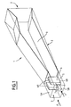
- Figure 1 is a very schematic perspective view of a example of a ramjet with masts fuel injection, the envelope of said ramjet being supposed to be transparent.
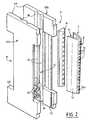
- Figure 2 is an exploded perspective view of an example of the fuel injection mast conforming to the present invention.
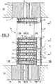
- Figure 3 is a median longitudinal section of the mast of the figure 2.
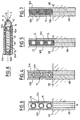
- Figures 4, 5, 6, 7 and 8 are cross sections of said fuel injection mast, corresponding respectively to cutting lines IV-IV, V-V, VI-VI, VII-VII and VIII-VIII of figure 3.
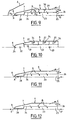
- Figure 9 is a schematic cross-section of a part of an injection mast according to the invention in the flow of fuel and oxidizer.
- Figure 10 is a schematic cross section of the part of the injection mast of Figure 9 in the walls of the engine, having lateral fuel supplies.
- FIGS 11 and 12 similar to Figure 9, illustrate two operating modes of the injection mast according to the invention.
- the ramjet 1, shown in Figure 1 is intended for the propulsion of a hypersonic aircraft (not shown) in front fly in a wide range of Mach number for example from around Mach 3 to a Mach number on the order of 12 to 15.
- the ramjet 1 has a casing 2 provided, at one of its ends, of an air intake 3 for an air stream to serve as oxidizer (symbolized by arrows F) and, at its opposite end, a nozzle 4. Downstream of the air intake 3, the casing 2 forms an injection chamber 5, inside which are arranged two injection masts of fuel 6, transverse to the vein of oxidizer F.
- the injection masts 6 each have a bow 7 having a leading edge 8, receiving said vein of oxidizer and are joined to the envelope 2, by their ends 6A and 6B fixed to the internal face of two walls opposite 5A and 5B of the injection chamber 5.
- the casing 2 defines a combustion chamber 9, at the upstream part of which igniters are provided (not shown).
- said injection masts 6 include longitudinal injection ramps (not visible on the Figure 1, but shown in Figure 3 in particular).
- the fuel is distributed throughout the vein of oxidizer F, at the level of the injection masts 6, and the combustion of the oxidant-fuel mixture flow in the combustion chamber 9, after which the gases from combustion are ejected through the nozzle 4.
- fuel kerosene can be used to lowest flight Mach numbers (up to Mach 8) (possibly with a bubbling of hydrogen so as to facilitate the ignition of the ramjet and the bursting of the jet), then hydrogen for the Mach numbers plus high.
- Other fuels such as methane, endothermic hydrocarbons, synthetic fuels, can also be used for a ramjet of this type.
- the casing 2 of the ramjet presents, in its together, a cross section pipe form rectangular or square, usually made up of four walls two by two opposite (supposed transparent on this figure 1). It is understood that such a configuration is in no way limiting.
- leading edge 8 of the bow 7 of the injection masts 6 undergoes very significant heat fluxes, when the oxidant vein corresponds to hypersonic flight. So, at Mach 12, the leading edge of the bow can be brought to a temperature of the order of 5000K.
- Figures 2 to 8 illustrate an embodiment for a injection mast 6, according to the invention and capable of withstand such high thermal stresses.
- the fuel injection mast 6 comprises a body 10, especially metallic, can be formed, as illustrated FIG. 2, of two assembled half-bodies 10A, 10B, and said bow 7, consisting of a piece, for example metallic, substantially in the form of a dihedral whose edge forms the leading edge 8 of the bow 7, and defining, in its concavity, one bedroom 11.
- the bow 7 is formed, at least in the vicinity of its leading edge 8, by a wall 12 permeable to jets of cooling fluid.
- the latter can be carried out, at least in the vicinity of the leading edge 8 of bow 7, made of a material permeable to coolant jets, i.e. in this case, the permeability of the wall is ensured by the porosity natural of the material used.
- the wall 12 of the stem 7 may have also a series of perforations 13, or a slot 13a (in dashed lines in Figure 2), extending along the edge 8 of the bow 7. Note that any other device ensuring the desired permeability while retaining sufficient mechanical strength can also be considered.
- the typical dimensions, at the level of the bow can be a thickness of the order of 30 mm, a leading edge radius millimeter, a 6 ° angle for the bow, a length of a few tens of centimeters, and a span that can reach 1 m.
- the drawing, especially the figure 2 should not be taken as specifically illustrative of this sizing, but it was rather developed in a concern for clarity of representation.
- an advantageous coolant is consisting of the fuel itself, a small part of which can be injected through the leading edge to cool the latter at the highest flight Mach (from Mach 6 for example), the structure will be described below in detail internal of the body 10 of the injection mast 6 according to the example of embodiment of the invention illustrated in FIGS. 2 to 8.
- the two half-bodies 10A, 10B define, inside the injection mast 6, an internal cavity 14 in which are arranged a plurality of elementary chambers 15 produced, each, in the form of a perforated cylinder open at both ends.
- the chambers 15 are arranged one above the other, and at a certain distance from each other, in the cavity 14 in a row, and a first end 15A of each of these opens into the concavity of the bow 7, of preferably through a corresponding port 16A of a part 16, constituting a sort of cover, covering all of the ends 15A of the chambers 15.
- Each other end 15B of the chambers 15, at the base of the injection mast 6, is produced in the form of a main injector combustible.
- an injector secondary fuel 17 is also provided at the base of the injection mast 6, in each interval between two chambers 15, an injector secondary fuel 17.
- the whole is supplied with fuel by channels supply 18 provided in the ends 6A, 6B of the mast 6 embedded in the opposite walls 5A, 5B of the chamber injection 5.
- the fuel is diffused in the cavity 14, through the perforated chambers 15, being channeled by longitudinal ribs 19 defining recesses 20 along the height of the cavity 14.
- pressure taps 21 are shown on the FIGS. 2 and 3, while the reference numeral 22 denotes, in FIG. 3, a support and holding plate for rooms 15 (see also Figure 5).
- Figures 9 and 10 further illustrate the invention, according to a simplified embodiment of the injection mast 6, further comprising a stem 7 having a leading edge permeable 8.
- FIG. 9 it is shown, according to a variant with respect to FIGS. 2 to 8 but whose principle remains the same, an internal chamber 23 to permeable wall 24.
- Main fuel injection in the vein is made through the holes 25, a secondary injection through the orifices 26, which injections can advantageously be sonic or supersonic.
- channel 28 allows communication between the edge of permeable attack 8 and the internal chamber 23.
- the external wall of the injection mast 6 can optionally be locally permeable (in 29), for example to evacuate, by film effect, a local excess heat flux, linked to the impact of a shock.
- Stiffeners 30 may be necessary for good performance mast mechanics.
- An ignition device 31 ( Figure 10), consisting of example of one or more electrically controlled candles, can be installed on the internal chamber.
- pressure measurements are used to manage injection according to the desired effect. We measure, for example, the pressure at the leading edge (sensor 32), that in the internal chamber (sensor 33) and the supply pressure in fuel (sensor 34). If desired, the temperature measurement (for example by thermocouple 35) of the leading edge wall can trigger cooling the latter.
- the direction of flow (admission of oxidant, in particular air or coolant injection, especially fuel) through the permeable leading edge of the mast bow - in other words, aspiration in mode "burner” or injection in “edge cooling” mode “( Figures 11 and 12) - is advantageously controlled by the pressure difference between the exterior (incident air) and inside the mast, without using any organ particular mobile mechanics (like a valve) at the level of the injection mast.
- the "burner" mode (figure 11) is used in the event of a problem of combustion, typically at a low Mach number supersonic, when the behavior of the material constituting the edge attack 7 of mast 6 is not called into question. This is translated by an air intake (arrow A) at the edge permeable attack (especially perforated) 8.
- the main effect of combustion in the pilot chamber 23 is the ignition and stabilization of the main combustion by creating a hot jet. Combustion in the pilot chamber taking place in a subsonic flow and at a constant section, it decreases the pressure, this which promotes the penetration of air through the edge attack.
- the ignition management is carried out as follows.
- the device control ignition provides an additional degree of freedom.
- the main combustion behind the mast injection can be done in a subsonic flow or supersonic. Air captured by the main air intake bypasses the injection mast and burns with fuel remaining in the rich burnt gases (arrow D) and with that injected at the arrows C, if applicable.
- At least one of the fuel supplies 27 can inject oxygen or another oxidizer in order to, for example, increase the thrust when the mission requires it (so-called ramjet operation at ejectors).
- the “leading edge cooling” mode (figure 12) is used when the holding of the material constituting the edge attack is involved. As already indicated, this is translated by injection of coolant (especially fuel) through the leading edge permeable 8 of the bow 7 of the injection mast 6.
- the internal chamber contains only fuel passing through it before being partially injected forward - in the direction of flow of the oxidizer - (to cool the leading edge 8 of the bow 7 by creation of a protective film around it), and backwards, forming the main injection of fuel (arrow D ') and possibly injections auxiliaries (arrows C), for injection and combustion in the engine.
- the advantages of the injection mast of fuel according to the invention are numerous. However, it is particularly suitable for a working ramjet over a wide range of Mach in supersonic and hypersonic and using, at least in part, a fuel which may present ignition difficulties, such as kerosene. It is also very useful when you want use supersonic combustion for flight mach less than 6 or when, for various reasons, aid to ignition is required.
- the basic idea of the invention is therefore, in addition to the fact of cool the leading edge of the injection mast by injecting, through it, a coolant (by fuel) at the highest speeds (mode "leading edge cooling"), to facilitate ignition at lower speeds by admitting air to inside the mast ("burner" mode), thus exploiting fully two-way permeability of the leading edge.
- valve function is obtained without mechanical device at the injection mast, simply by managing the pressure differential between the air incident and inside the mast.
Description
- d'assurer une alimentation de combustible dans toute la veine de comburant, malgré la faible pénétration des jets de combustible dans une veine de comburant à vitesse hypersonique ;
- d'augmenter la proportion de combustible dans le mélange comburant-combustible ;
- d'aider à l'allumage du mélange comburant-combustible et à stabiliser la flamme ;
- de participer à la compression de la veine de comburant, en ralentissant l'écoulement de comburant capté par le statoréacteur.
- ladite étrave est formée, au moins au voisinage de son bord d'attaque, par une paroi perméable, et
- ledit mât comporte :
- une chambre prévue dans la concavité de ladite paroi perméable de l'étrave, et
- des moyens d'injection d'un fluide de refroidissement dans ladite chambre, lesdits moyens d'injection étant aptes à engendrer une pluralité de jets de fluide de refroidissement répartis le long de la hauteur de ladite étrave et frappant la face concave de ladite paroi perméable, au moins dans la région dudit bord d'attaque, de façon à traverser ladite paroi perméable.
- sur l'alimentation en ergols avec une pression donnée,
- sur l'utilisation ou non du dispositif d'allumage,
- à partir des mesures provenant des capteurs de pression et de température.
- la pression y reste faible, le mélange est riche et les flux thermiques engendrés restent raisonnables,
- le combustible refroidit cette chambre (qui de plus peut
être constituée d'un matériau résistant à haute température
si nécessaire) :
- 1/ par circulation, en particulier dans le cas où on utilise une injection de combustible (flèches C),
- 2/ par refroidissement pariétal (transpiration ou effusion) si on choisit une technologie de paroi perméable pour la chambre pilote, comme on le voit sur la figure 11.
- Pa : la pression de l'air derrière la partie droite du choc détaché Δ au bord d'attaque 8 du mât,
- Pci : la pression dans la chambre interne,
- Pe : la pression d'injection du combustible ou plus
généralement des ergols (c'est-à-dire celle injectée dans
le mât et régulée, aux pertes de charge près),
on notera que :
- Pa dépend de la forme du mât et des conditions aérodynamiques incidentes,
- Pe est réglée en fonction de l'effet à obtenir et de la réponse du système,
- Pci est le résultat du fonctionnement choisi.
- la pression d'alimentation qui engendre Pe,
- l'utilisation ou non (OUI ; NON) du dispositif d'allumage.
| Pa (bar) | Pe (bar) | Pci (bar) | ||
| Mach 3 | OUI | 2,6 | 2 | 8 |
| Mach 5 | NON | 6 | 4 | 10 |
| Mach 6 | NON | 7,5 | 25 | 30 |
| Mach 8 | NON | 9 | 25 | 30 |
| Mach 15 | NON | 10 | 40 | 45 |
Claims (14)
- Mât (6) d'injection de combustible pour un statoréacteur (1) destiné à fonctionner à un nombre de Mach élevé et comportant une chambre de combustion (8) dans laquelle est introduite une veine de comburant (F), ledit mât (6) comportant une étrave (7) ayant un bord d'attaque (8) recevant ladite veine de comburant et formant, au culot dudit mât, une rampe d'injecteurs élémentaires de combustible, disposée dans ladite veine de comburant transversalement à celle-ci et répartissant ledit combustible dans ladite veine de comburant,
caractérisé en ce que :ladite étrave (7) est formée, au moins au voisinage de son bord d'attaque (8), par une paroi (12) dans la concavité de laquelle est disposée une chambre (11) ;des moyens d'injection (15, 18) sont aptes à engendrer, dans ladite chambre (11), une pluralité de jets d'un fluide de refroidissement répartis le long de ladite étrave (7) et frappant la face concave de ladite paroi (12), au moins dans la région dudit bord d'attaque (8) ; etladite paroi (12) est perméable aux jets de fluide de refroidissement qui la frappent sur sa face concave, de sorte que lesdits jets de fluide de refroidissement traversent ladite paroi (12). - Mât d'injection selon la revendication 1, caractérisé en ce que ladite paroi (12) de l'étrave (7) est réalisée, au moins au voisinage du bord d'attaque (8) de cette dernière, en un matériau perméable aux jets de fluide de refroidissement.
- Mât d'injection selon la revendication 1, caractérisé en ce que ladite paroi (12) de l'étrave (7) présente au moins une série de perforations (13) s'étendant le long du bord d'attaque (8) de l'étrave (7).
- Mât d'injection selon la revendication 1, caractérisé en ce que ladite paroi (12) de l'étrave (7) présente au moins une fente (13a) s'étendant le long du bord d'attaque (8) de l'étrave (7).
- Mât d'injection selon l'une quelconque des revendications 1 à 4, caractérisé en ce que le fluide de refroidissement est constitué par du combustible.
- Mât d'injection selon l'une quelconque des revendications 1 à 5, caractérisé en ce que ladite étrave (7) est constituée d'une pièce sensiblement en forme de dièdre dont l'arête forme le bord d'attaque (8) de l'étrave, et définissant, dans sa concavité, une chambre (11).
- Mât d'injection selon la revendication 5 ou 6, caractérisé en ce qu'il comporte un corps (10) définissant, à l'intérieur du mât d'injection (6), une cavité interne (14) dans laquelle sont agencées une pluralité de chambres élémentaires (15) réalisées, chacune, sous forme d'un cylindre perforé ouvert aux deux extrémités.
- Mât d'injection selon la revendication 7, caractérisé en ce que lesdites chambres élémentaires (15) sont disposées l'une au-dessus de l'autre, et à un certain écartement l'une de l'autre, dans ladite cavité (14) en une rangée.
- Mât d'injection selon la revendication 8, caractérisé en ce qu'une première extrémité (15A) de chacune desdites chambres (15) débouche dans la concavité de ladite étrave (7), tandis que chaque autre extrémité (15B) desdites chambres (15), au culot du mât d'injection (6), est réalisée sous forme d'injecteur principal de combustible.
- Mât d'injection selon la revendication 9, caractérisé en ce qu'une pièce en forme de capot (16), munie d'orifices correspondants (16A), recouvre l'ensemble des premières extrémités (15A) desdites chambres (15).
- Mât d'injection selon l'une quelconque des revendications 7 à 10, caractérisé en ce que, au culot du mât (6), il est prévu, dans chaque intervalle entre deux chambres élémentaires (15), un injecteur secondaire de combustible (17).
- Mât d'injection selon l'une quelconque des revendications 7 à 11, caractérisé en ce que l'alimentation en combustible dudit mât est assurée par des canaux d'alimentation (18) prévus dans les extrémités (6A, 6B) du mât (6) encastrées dans les parois opposées (5A, 5B) de la chambre d'injection (5) du statoréacteur.
- Mât d'injection selon l'une quelconque des revendications 1 à 12, caractérisé en ce qu'il comprend des capteurs (32, 33, 34) de mesure de la pression au bord d'attaque, de celle à l'intérieur du mât et de la pression d'alimentation en combustible.
- Mât d'injection selon l'une quelconque des revendications 1 à 13,
caractérisé en ce qu'il comporte un capteur (35) de mesure de la température de la paroi du bord d'attaque.
Applications Claiming Priority (2)
| Application Number | Priority Date | Filing Date | Title |
|---|---|---|---|
| FR9614786A FR2756593B1 (fr) | 1996-12-03 | 1996-12-03 | Mat d'injection de combustible pour un statoreacteur fonctionnant sur une large plage de nombre de mach |
| FR9614786 | 1996-12-03 |
Publications (2)
| Publication Number | Publication Date |
|---|---|
| EP0846920A1 EP0846920A1 (fr) | 1998-06-10 |
| EP0846920B1 true EP0846920B1 (fr) | 2003-06-11 |
Family
ID=9498258
Family Applications (1)
| Application Number | Title | Priority Date | Filing Date |
|---|---|---|---|
| EP97402899A Expired - Lifetime EP0846920B1 (fr) | 1996-12-03 | 1997-12-02 | Mât d'injection de combustible pour un statoréacteur refroidi par perspiration |
Country Status (9)
| Country | Link |
|---|---|
| US (1) | US6164061A (fr) |
| EP (1) | EP0846920B1 (fr) |
| JP (1) | JP3917668B2 (fr) |
| CA (1) | CA2223546C (fr) |
| DE (1) | DE69722750T2 (fr) |
| ES (1) | ES2201257T3 (fr) |
| FR (1) | FR2756593B1 (fr) |
| RU (1) | RU2157908C2 (fr) |
| WO (1) | WO1998025083A1 (fr) |
Cited By (2)
| Publication number | Priority date | Publication date | Assignee | Title |
|---|---|---|---|---|
| CN103672966A (zh) * | 2013-11-12 | 2014-03-26 | 清华大学 | 利用发汗冷却对超燃发动机燃料喷注支板的热防护方法 |
| CN108317542A (zh) * | 2018-01-03 | 2018-07-24 | 南方科技大学 | 航空发动机燃烧室的冷却结构及航空发动机燃烧室 |
Families Citing this family (21)
| Publication number | Priority date | Publication date | Assignee | Title |
|---|---|---|---|---|
| US6883330B2 (en) * | 2002-10-02 | 2005-04-26 | United Technologies Corporation | Variable geometry inlet design for scram jet engine |
| US20070261816A1 (en) * | 2006-03-27 | 2007-11-15 | Warren Charles J | Hood mounted heat exchanger |
| US7797943B2 (en) | 2006-10-18 | 2010-09-21 | Aerojet-General Corporation | Core burning for scramjet engines |
| DE102008032265B4 (de) * | 2008-07-09 | 2010-06-10 | Deutsches Zentrum für Luft- und Raumfahrt e.V. | Verbrennungsvorrichtung |
| RU2444639C1 (ru) * | 2010-10-25 | 2012-03-10 | Российская Федерация, от имени которой выступает Министерство промышленности и торговли Российской Федерации Минпромторг России | Способ автовоспламенения топливной смеси в камере сгорания прямоточного воздушно-реактивного двигателя |
| US9371800B2 (en) * | 2011-03-01 | 2016-06-21 | Grollo Aerospace | Engine for use in an aerial vehicle |
| US9212822B2 (en) * | 2012-05-30 | 2015-12-15 | General Electric Company | Fuel injection assembly for use in turbine engines and method of assembling same |
| CN103411236B (zh) * | 2013-09-01 | 2015-02-25 | 北京航空航天大学 | 一种开孔侧裙板式值班火焰稳定器 |
| RU2543915C1 (ru) * | 2013-10-03 | 2015-03-10 | Федеральное государственное унитарное предприятие "Центральный институт авиационного моторостроения им. П.И. Баранова" | Способ воспламенения топливной смеси в высокоскоростном врд |
| CN106247407A (zh) * | 2016-08-15 | 2016-12-21 | 西北工业大学 | 一种燃料支板喷注器 |
| WO2020123000A2 (fr) * | 2018-09-12 | 2020-06-18 | University Of Florida Research Foundation, Inc. | Injecteur de carburant pour fonctionnement de moteur à réaction hypersonique |
| US11267551B2 (en) | 2019-11-15 | 2022-03-08 | General Electric Company | System and method for cooling a leading edge of a high speed vehicle |
| US11427330B2 (en) | 2019-11-15 | 2022-08-30 | General Electric Company | System and method for cooling a leading edge of a high speed vehicle |
| US11260976B2 (en) | 2019-11-15 | 2022-03-01 | General Electric Company | System for reducing thermal stresses in a leading edge of a high speed vehicle |
| US11260953B2 (en) | 2019-11-15 | 2022-03-01 | General Electric Company | System and method for cooling a leading edge of a high speed vehicle |
| US11352120B2 (en) | 2019-11-15 | 2022-06-07 | General Electric Company | System and method for cooling a leading edge of a high speed vehicle |
| CN114440260B (zh) * | 2020-10-30 | 2023-05-30 | 西安航天动力研究所 | 燃烧室用高温合金丝网编织的定向发汗冷却凹腔装置 |
| US11745847B2 (en) | 2020-12-08 | 2023-09-05 | General Electric Company | System and method for cooling a leading edge of a high speed vehicle |
| US11407488B2 (en) | 2020-12-14 | 2022-08-09 | General Electric Company | System and method for cooling a leading edge of a high speed vehicle |
| US11577817B2 (en) | 2021-02-11 | 2023-02-14 | General Electric Company | System and method for cooling a leading edge of a high speed vehicle |
| CN113464976B (zh) * | 2021-05-12 | 2022-08-05 | 深圳市万泽航空科技有限责任公司 | 一种火焰稳定器及其制造方法 |
Family Cites Families (14)
| Publication number | Priority date | Publication date | Assignee | Title |
|---|---|---|---|---|
| FR1177045A (fr) * | 1957-05-28 | 1959-04-20 | Messerschmitt Ag | Aubes mobiles de turbines à gaz, à refroidissement superficiel |
| US3727409A (en) * | 1961-03-30 | 1973-04-17 | Garrett Corp | Hypersonic aircraft engine and fuel injection system therefor |
| US3556443A (en) * | 1968-07-23 | 1971-01-19 | Robert P Kidwell | Boundary layer control of airborne vehicles |
| US3699773A (en) * | 1968-12-23 | 1972-10-24 | Gen Electric | Fuel cooled fuel injectors |
| US3808833A (en) * | 1973-04-03 | 1974-05-07 | Us Navy | Compact transpiration cooling system |
| US4986068A (en) * | 1988-09-16 | 1991-01-22 | General Electric Company | Hypersonic scramjet engine fuel injector |
| US4903480A (en) * | 1988-09-16 | 1990-02-27 | General Electric Company | Hypersonic scramjet engine fuel injector |
| US5214914A (en) * | 1990-04-30 | 1993-06-01 | The Johns Hopkins University | Translating cowl inlet with retractable propellant injection struts |
| JP2580510B2 (ja) * | 1991-08-19 | 1997-02-12 | 科学技術庁航空宇宙技術研究所長 | 高速航空エンジン用燃焼器 |
| US5351917A (en) * | 1992-10-05 | 1994-10-04 | Aerojet General Corporation | Transpiration cooling for a vehicle with low radius leading edges |
| FR2706588B1 (fr) * | 1993-06-16 | 1995-07-21 | Snecma | Système d'injection de carburant pour chambre de combustion. |
| US5396761A (en) * | 1994-04-25 | 1995-03-14 | General Electric Company | Gas turbine engine ignition flameholder with internal impingement cooling |
| US5660040A (en) * | 1994-12-20 | 1997-08-26 | United Technologies Corporation | Scramjet fuel injection system having independent fuel supplies for supersonic and hypersonic operation |
| FR2750169B1 (fr) * | 1996-06-24 | 1998-08-21 | Aerospatiale | Dispositif d'injection de combustible pour statoreacteur fonctionnant a un nombre de mach eleve |
-
1996
- 1996-12-03 FR FR9614786A patent/FR2756593B1/fr not_active Expired - Lifetime
-
1997
- 1997-11-28 CA CA002223546A patent/CA2223546C/fr not_active Expired - Fee Related
- 1997-12-02 EP EP97402899A patent/EP0846920B1/fr not_active Expired - Lifetime
- 1997-12-02 ES ES97402899T patent/ES2201257T3/es not_active Expired - Lifetime
- 1997-12-02 US US09/101,841 patent/US6164061A/en not_active Expired - Lifetime
- 1997-12-02 JP JP52527498A patent/JP3917668B2/ja not_active Expired - Lifetime
- 1997-12-02 RU RU98116452/06A patent/RU2157908C2/ru active
- 1997-12-02 WO PCT/FR1997/002176 patent/WO1998025083A1/fr active Application Filing
- 1997-12-02 DE DE69722750T patent/DE69722750T2/de not_active Expired - Lifetime
Cited By (3)
| Publication number | Priority date | Publication date | Assignee | Title |
|---|---|---|---|---|
| CN103672966A (zh) * | 2013-11-12 | 2014-03-26 | 清华大学 | 利用发汗冷却对超燃发动机燃料喷注支板的热防护方法 |
| CN103672966B (zh) * | 2013-11-12 | 2015-06-24 | 清华大学 | 利用发汗冷却对超燃发动机燃料喷注支板的热防护方法 |
| CN108317542A (zh) * | 2018-01-03 | 2018-07-24 | 南方科技大学 | 航空发动机燃烧室的冷却结构及航空发动机燃烧室 |
Also Published As
| Publication number | Publication date |
|---|---|
| EP0846920A1 (fr) | 1998-06-10 |
| RU2157908C2 (ru) | 2000-10-20 |
| ES2201257T3 (es) | 2004-03-16 |
| JP3917668B2 (ja) | 2007-05-23 |
| CA2223546A1 (fr) | 1998-06-03 |
| DE69722750T2 (de) | 2004-04-29 |
| CA2223546C (fr) | 2005-04-05 |
| WO1998025083A1 (fr) | 1998-06-11 |
| JP2000504394A (ja) | 2000-04-11 |
| US6164061A (en) | 2000-12-26 |
| FR2756593B1 (fr) | 1999-01-22 |
| DE69722750D1 (de) | 2003-07-17 |
| FR2756593A1 (fr) | 1998-06-05 |
Similar Documents
| Publication | Publication Date | Title |
|---|---|---|
| EP0846920B1 (fr) | Mât d'injection de combustible pour un statoréacteur refroidi par perspiration | |
| EP0604279B1 (fr) | Injecteur avec paroi poreuse pour chambre de combustion d'une fusée | |
| EP2525070B1 (fr) | Statoréacteur à chambre de détonation et engin volant comprenant un tel statoréacteur | |
| EP2042806B1 (fr) | Chambre de combustion d'une turbomachine | |
| CA2198420C (fr) | Dispositif d'injection de combustible pour statoreacteur d'aeronef | |
| EP0434565A1 (fr) | Moteur à propulsion combinée à haute adaptabilité pour aéronef ou avion spatial | |
| FR2658868A1 (fr) | Moteur de statoreacteur a combustion supersonique et procede de fonctionnement d'un tel moteur. | |
| EP1342905B1 (fr) | Moteur de fusée | |
| EP0816664B1 (fr) | Dispositif d'injection de combustible pour statoréacteur fonctionnand à un nombre de mach élevé | |
| EP0816665B1 (fr) | Mât d'injection de combustible pour statoréacteur fonctionnant à un nonbre de mach élevé | |
| EP1342904B1 (fr) | Chambre de combustion pour statoréacteur et statoréacteur pourvu d'une telle chambre de combustion | |
| FR2736684A1 (fr) | Statoreacteur pour aeronef a vol supersonique et/ou hypersonique | |
| FR2549146A1 (fr) | Ensemble propulsif pour missile statoreacteur a propulseur d'acceleration integre | |
| EP4004443B1 (fr) | Chambre de combustion comportant des systèmes d'injection secondaires et procédé d'alimentation en carburant | |
| EP0793011B1 (fr) | Statoréacteur à géométrie évolutive pour aéronef | |
| EP1101030B1 (fr) | Tuyere compacte et modulable pour le pilotage d'engins aerospatiaux | |
| CA2262059C (fr) | Moteur mixte susceptible de mettre en oeuvre au moins un mode statoreacteur et un mode superstatoreacteur | |
| FR2650341A1 (fr) | Generateur de gaz pour stato-fusees | |
| CA2180501C (fr) | Statoreacteur pour aeronef a vol supersonique et/ou hypersonique | |
| WO1999034105A1 (fr) | Allumeur acoustique et procede d'allumage pour moteur-fusee a ergols liquides | |
| WO2018134501A2 (fr) | Chambre de combustion de turbomachine a haute permeabilite | |
| CA3233988A1 (fr) | Dispositif d'injection de dihydrogene et d'air |
Legal Events
| Date | Code | Title | Description |
|---|---|---|---|
| PUAI | Public reference made under article 153(3) epc to a published international application that has entered the european phase |
Free format text: ORIGINAL CODE: 0009012 |
|
| AK | Designated contracting states |
Kind code of ref document: A1 Designated state(s): BE DE ES GB IT NL SE |
|
| AX | Request for extension of the european patent |
Free format text: AL;LT;LV;MK;RO;SI |
|
| 17P | Request for examination filed |
Effective date: 19980701 |
|
| AKX | Designation fees paid |
Free format text: BE DE ES GB IT NL SE |
|
| RBV | Designated contracting states (corrected) |
Designated state(s): BE DE ES GB IT NL SE |
|
| RAP1 | Party data changed (applicant data changed or rights of an application transferred) |
Owner name: AEROSPATIALE MATRA |
|
| GRAH | Despatch of communication of intention to grant a patent |
Free format text: ORIGINAL CODE: EPIDOS IGRA |
|
| GRAH | Despatch of communication of intention to grant a patent |
Free format text: ORIGINAL CODE: EPIDOS IGRA |
|
| GRAA | (expected) grant |
Free format text: ORIGINAL CODE: 0009210 |
|
| AK | Designated contracting states |
Designated state(s): BE DE ES GB IT NL SE |
|
| REG | Reference to a national code |
Ref country code: GB Ref legal event code: FG4D Free format text: NOT ENGLISH |
|
| REF | Corresponds to: |
Ref document number: 69722750 Country of ref document: DE Date of ref document: 20030717 Kind code of ref document: P |
|
| GBT | Gb: translation of ep patent filed (gb section 77(6)(a)/1977) |
Effective date: 20030730 |
|
| REG | Reference to a national code |
Ref country code: SE Ref legal event code: TRGR |
|
| REG | Reference to a national code |
Ref country code: ES Ref legal event code: FG2A Ref document number: 2201257 Country of ref document: ES Kind code of ref document: T3 |
|
| PLBE | No opposition filed within time limit |
Free format text: ORIGINAL CODE: 0009261 |
|
| STAA | Information on the status of an ep patent application or granted ep patent |
Free format text: STATUS: NO OPPOSITION FILED WITHIN TIME LIMIT |
|
| 26N | No opposition filed |
Effective date: 20040312 |
|
| PGFP | Annual fee paid to national office [announced via postgrant information from national office to epo] |
Ref country code: GB Payment date: 20161221 Year of fee payment: 20 Ref country code: NL Payment date: 20161117 Year of fee payment: 20 |
|
| PGFP | Annual fee paid to national office [announced via postgrant information from national office to epo] |
Ref country code: SE Payment date: 20161219 Year of fee payment: 20 Ref country code: IT Payment date: 20161214 Year of fee payment: 20 Ref country code: BE Payment date: 20161216 Year of fee payment: 20 Ref country code: ES Payment date: 20161229 Year of fee payment: 20 |
|
| PGFP | Annual fee paid to national office [announced via postgrant information from national office to epo] |
Ref country code: DE Payment date: 20161221 Year of fee payment: 20 |
|
| REG | Reference to a national code |
Ref country code: DE Ref legal event code: R071 Ref document number: 69722750 Country of ref document: DE |
|
| REG | Reference to a national code |
Ref country code: NL Ref legal event code: MK Effective date: 20171201 |
|
| REG | Reference to a national code |
Ref country code: GB Ref legal event code: PE20 Expiry date: 20171201 |
|
| REG | Reference to a national code |
Ref country code: SE Ref legal event code: EUG |
|
| REG | Reference to a national code |
Ref country code: BE Ref legal event code: MK Effective date: 20171202 |
|
| PG25 | Lapsed in a contracting state [announced via postgrant information from national office to epo] |
Ref country code: GB Free format text: LAPSE BECAUSE OF EXPIRATION OF PROTECTION Effective date: 20171201 |
|
| REG | Reference to a national code |
Ref country code: ES Ref legal event code: FD2A Effective date: 20180508 |
|
| PG25 | Lapsed in a contracting state [announced via postgrant information from national office to epo] |
Ref country code: ES Free format text: LAPSE BECAUSE OF EXPIRATION OF PROTECTION Effective date: 20171203 |