EP0846612B1 - Vehicle body panel assembly - Google Patents
Vehicle body panel assembly Download PDFInfo
- Publication number
- EP0846612B1 EP0846612B1 EP97309530A EP97309530A EP0846612B1 EP 0846612 B1 EP0846612 B1 EP 0846612B1 EP 97309530 A EP97309530 A EP 97309530A EP 97309530 A EP97309530 A EP 97309530A EP 0846612 B1 EP0846612 B1 EP 0846612B1
- Authority
- EP
- European Patent Office
- Prior art keywords
- panel
- alignment member
- frame
- assembly
- alignment
- Prior art date
- Legal status (The legal status is an assumption and is not a legal conclusion. Google has not performed a legal analysis and makes no representation as to the accuracy of the status listed.)
- Expired - Lifetime
Links
- 238000000034 method Methods 0.000 claims abstract description 11
- 125000006850 spacer group Chemical group 0.000 claims description 6
- 230000007246 mechanism Effects 0.000 description 5
- 230000000717 retained effect Effects 0.000 description 4
- 229910000831 Steel Inorganic materials 0.000 description 1
- 206010042618 Surgical procedure repeated Diseases 0.000 description 1
- 230000000712 assembly Effects 0.000 description 1
- 238000000429 assembly Methods 0.000 description 1
- 230000001419 dependent effect Effects 0.000 description 1
- 238000012986 modification Methods 0.000 description 1
- 230000004048 modification Effects 0.000 description 1
- 239000010959 steel Substances 0.000 description 1
Images


Classifications
-
- B—PERFORMING OPERATIONS; TRANSPORTING
- B62—LAND VEHICLES FOR TRAVELLING OTHERWISE THAN ON RAILS
- B62D—MOTOR VEHICLES; TRAILERS
- B62D25/00—Superstructure or monocoque structure sub-units; Parts or details thereof not otherwise provided for
- B62D25/08—Front or rear portions
- B62D25/10—Bonnets or lids, e.g. for trucks, tractors, busses, work vehicles
-
- Y—GENERAL TAGGING OF NEW TECHNOLOGICAL DEVELOPMENTS; GENERAL TAGGING OF CROSS-SECTIONAL TECHNOLOGIES SPANNING OVER SEVERAL SECTIONS OF THE IPC; TECHNICAL SUBJECTS COVERED BY FORMER USPC CROSS-REFERENCE ART COLLECTIONS [XRACs] AND DIGESTS
- Y10—TECHNICAL SUBJECTS COVERED BY FORMER USPC
- Y10T—TECHNICAL SUBJECTS COVERED BY FORMER US CLASSIFICATION
- Y10T29/00—Metal working
- Y10T29/49—Method of mechanical manufacture
- Y10T29/49826—Assembling or joining
- Y10T29/49895—Associating parts by use of aligning means [e.g., use of a drift pin or a "fixture"]
- Y10T29/49902—Associating parts by use of aligning means [e.g., use of a drift pin or a "fixture"] by manipulating aligning means
Definitions
- the present invention relates to a vehicle body panel assembly for a vehicle having a chassis, and to a method for assembling the same.
- the invention is particularly suited to a tractor engine hood or bonnet assembly.
- a problem encountered when assembling two or more body panels to a frame is that of aligning the panels with respect to each other, so that a uniform small gap is maintained between the edges of the respective panels.
- the problem is particularly apparent when the precise position and orientation of a given panel is determined by a mounting point or points remote from an edge of that panel which needs to be lined up closely with an adjacent panel.
- the problem is also more evident in assemblies where one of the panels needs to be easily released by some latching means.
- US 4,491,191 describes an arrangement for assembling vehicle body panels according to the preamble of claim 1 wherein the front grille panel and the side / top body panels are attached to common brackets, which provide for adjustment of the alignment of the body panel and front grille.
- aligning the panels is difficult, since each panel can move with respect to the other panels, and the common brackets are not fixed in position.
- An object of the present invention is to alleviate the problem at least in part. According to an aspect of the present invention, there is provided a body panel assembly as specified in Claim 1.
- this arrangement permits adjustments to the position and orientation of the second panel to be made to ensure that the edges of the first and second panels are accurately aligned. Accurate alignment of the panels is obviously important for aesthetic reasons, and also to ensure that the panel assembly is providing the intended degree of protection from the weather, etc, to the interior space defined within the assembly.
- the invention defined above is particularly useful when the second body panel needs to be releasably mounted, since a releasable latch assembly can be mounted on the alignment member.
- the alignment member is pivotally secured to the frame adjacent a first substantially straight edge of the second body panel whereby the alignment member is pivotable about an axis substantially parallel to the said edge until secured by the said adjustable fastening means.
- the second panel may be mounted directly to the frame at a mounting point or points adajcent one edge of the panel, and the position of the opposite edge of the panel, which is mounted on the alignment member, determined by the adjustable fastening means.
- Another possibility is to provide close tolerance apertures in the first body panel and alignment member respectively, a corresponding aperture of large dimensions being provided in the frame, whereby during assembly the relative positions of the first panel and alignment member may be set by inserting an aligning rod, whose dimensions closely match the said close tolerance apertures, through the said apertures in the first panel, frame and alignment member respectively.
- This arrangement may be useful when the degrees of freedom of the alignment member are not restricted by mounting it for pivotal or sliding movement only.
- FIG. 1 The front portion 1 of the chassis of an agricultural tractor is shown in Figure 1.
- An engine 2 is shown mounted on the chassis 1 and, in front of that, a front mounting bracket or frame 3 is bolted to the chassis 1 whose purpose is to provide a forward mounting for the hood or bonnet panelling shown generally at 4.
- the frame 3 is, in very general terms, a piece of inverted "U" section plate steel with side members 6 bolted to and extending upwardly from the chassis and a top member 7 extending between the upper ends of the side members 6.
- the frame 3 is a unitary member but it could equally well comprise a number of separate members bolted together or alternatively it could be cast integrally with the chassis 1.
- a top body panel 8 comprising the top of the engine hood is located at its forward end on the top member 7 by means of an upstanding spigot 9 on the top member which is received in a fairly closely toleranced aperture 10 in a channel portion 11 of the top panel 8.
- the rear of the top panel 8 is secured to the rear of the engine, in practice, but this is not relevant to the present invention other than to mention that the distance between these two mounting points (a metre or more) will obviously affect the precision of the alignment of the front and rear mounting points.
- Each side panel 12 is hung from each side edge 13 of the top panel 8 by conventional means such as locating pegs.
- Each side panel 12 is formed with a flange 14 along its forward edge which, when the panel assembly is complete, is not visible.
- Formed in the flange 14 of each side panel 12 are upper 15 and lower 16 closely toleranced apertures.
- Right and left alignment members 17 are provided, which are secured to the inside surfaces of the side members 6 of the mounting frame 3.
- the purpose of the alignment members is to carry a front grille panel member 18.
- Each alignment member 17 is formed with upper 19 and lower 20 close tolerance apertures corresponding with the upper and lower apertures on the respective side panel flange 14. Approximately in registry with these holes in the flange and alignment member are relatively large upper 21 and lower 22 apertures in each side member 6 of the mounting frame 3.
- each alignment member 17 Formed on the front edge of each alignment member 17 is an inwardly turned (or alternatively outwardly turned) flange 23 carrying one part 24 of a releasable latch, the corresponding part (not shown) being on the inner face of the front grille panel 18.
- each alignment member 17 At the base of each alignment member 17 is an upwardly opening slot 25 which comprises part of a releasable hinge mounting between the alignment member and the front grille panel 18.
- the corresponding part of the hinge mounting comprises a simple horizontal bar (not shown) mounted on the inner face of the grille panel 18 at the bottom. The location of these parts of the hinge mounting may of course be reversed.
- the alignment members 17 are first of all located with respect to the frame 3 and side panels 12.
- An alignment member 17 is first offered up to the interior surface of the corresponding side member 6 so that the apertures 19 and 20 are approximately in line with the apertures 21 and 22 in the side member 6.
- the apertures 15 and 16 in the side panel flange 14 will already be approximately in registry with the apertures 21, 22 in the side members 6.
- An alignment device (not shown) comprising a circular cross section rod, which is a close tolerance fit in the apertures 15, 16, 19, 20 in the flange 14 and alignment member 17, is then inserted through the upper apertures 15, 19 and 21.
- the upper part of the alignment member 17 is thereby accurately aligned with respect to the side panel 12, provided the alignment member is retained closely against the interior surface of the side member 6 so that the alignment device is retained perpendicular to the flange 14, side member 6 and alignment member 17.
- the alignment device 17 is then retained in place whilst the alignment device is removed and re-inserted in to the lower apertures 16, 20, 22 and the procedure repeated.
- the alignment device may be left in position in the upper apertures and a further alignment device inserted into the lower apertures.
- the member is held in place whilst the alignment device or devices is/are removed and bolts are then inserted through the upper and lower sets of holes in the side panel, side member and alignment member to secure the three together. It will be appreciated that once the bolts are tightened, any free play permitted by the relatively large apertures 21, 22 in the side member 6 and which was necessary to adjust the position of the alignment member 17 will no longer be possible. Similarly any free play permitted between the bolts and the apertures 15, 16, 19, 20 in the flange 14 and alignment member 17 will be prevented once the bolts are fully tightened.
- the grille panel 18 may then be simply mounted on the alignment members 17 by inserting the horizontal bars mentioned above on the interior face of the grille panel 18 into the slots 25 on the alignment members and then hinging the grille panel 18 against the alignment mbmers so that the releasable latches engage.
- the gap between the grille panel 18 and the exterior surface of each side panel 12 can be set with accuracy and precision.
- each flange 14 which need not be closely toleranced are provided in each flange 14, side member 6 and alignment member 17 for receiving fastening bolts.
- the alignment device or devices are maintained in place whilst bolts are fitted to this further set of apertures to fasten the alignment member to the frame 3 and side panel 12, whereafter the alignment device or devices is/are removed.
- the side panels 12 are, as in the first embodiment, bolted to the side members 6 of the mounting frame 3.
- the alignment members 17 of the first embodiment are, however, replaced by a single alignment member 26 in the form of a plate mounted on the chassis 1 or on a base member 5 of the mounting frame 3 by means of two bolts passing through elongate holes 27 in the alignment member 26.
- the alignment member 26 is also formed with upstanding lugs 28 towards the forward edge thereof. Each lug 28 has an upwardly open slot 29 formed in it.
- the side members 6 of the frame 3 are different to those of the first embodiment in that they are equipped only with simple apertures corresponding to the apertures in the flanges 14 for bolting the side panels 12 to the frame 3.
- Each flange 30 carries part 31 of a releasable latch mechanism, similar to the latch parts 24 in the first embodiment.
- the grille panel 18 is identical or very similar to the panel of the first embodiment in that it is formed with bar members on the bottom edge of the inside face for co-operating with the slots 29 to form a releasable hinge, and also with corresponding parts of latch mechanisms for engaging with the latch mechanism parts 31 on the flanges 30.
- the grille member 18 is mounted on the latch mechanism parts 31 and in the slots 29. The lower end of the grille panel 18 is then moved in and out with the alignment member 26. The small amount of pivotal movement necessary at the upper part of the panel 18 is permitted by the latches 31, and the inward and outward movement of the lower part of the panel 18 and alignment member 26 is permitted by the elongate nature of the bolt holes 27 in the alignment member 26.
- One of a series of differently sized spacer devices (eg simple plastic blocks), is found which fits in the gap between the top panel 8 and the upper edge of the grille member 18. The grille member 18 is then moved in or out until this same spacer device is a snug fit in the entire length of the gap between each side panel 12 and the grille panel 18.
- the grille panel is then removed and the mounting bolts in the slots 27 tightened to secure the alignment member 26 to the base member 5 of the frame 3.
- the second embodiment allows the alignment of the grille panel 18 with respect to the side panels 12 to be set with accuracy and precision, but relies on other aspects of the body panel assembly for the accuracy and precision of the dimensions of the spacing.
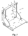
- FIG. 3 shows only the mounting frame 3 and alignment members 17 of the third embodiment.
- the mounting frame 3 is of slightly different design to the first and second embodiments, and the alignment members 17 are of similar design to the alignment members of the first embodiment, although with slight differences as will be explained below.
- the reference numerals for parts of the mounting frame 3 and alignment members 17 which essentially correspond between first and third embodiments are retained.
- the third embodiment is similar to the second embodiment in that the intention is to use the alignment members only to ensure that the gap between the top and side panels and the front grille panel 18 is constant, and reliance is placed on different aspects of the structure to ensure the accuracy and precision of the exact dimension of the gap.
- each alignment member 17 carries a flange 23 to which is attached part 24 of a releasable latch mechanism.
- Mounting holes 33 are provided for fixing the exact orientation of the alignment member to the respective side member 6 via mounting holes 34 in the side member. The holes 33, 34 and the bolts used sized so as to allow a certain amount of free play until the bolts are tightened.
- each alignment member 17 is formed an upwardly open slot 25 as in the first embodiment.
- the front grille panel 18 is releasably mounted in the slots 25 and on the latch 24, by means of corresponding parts on the interior surface of the grille panel 18.
- the grille panel is first mounted on the alignment member 17, as with the second embodiment.
- a spacer device is then used to ensure that the gap at the top and on each side of the grille panel 18 is uniform. Once this is done, the grille panel is removed and the alignment members bolted to the respective side members 6.
Landscapes
- Engineering & Computer Science (AREA)
- Chemical & Material Sciences (AREA)
- Combustion & Propulsion (AREA)
- Transportation (AREA)
- Mechanical Engineering (AREA)
- Body Structure For Vehicles (AREA)
- Vehicle Interior And Exterior Ornaments, Soundproofing, And Insulation (AREA)
- Superstructure Of Vehicle (AREA)
- Laminated Bodies (AREA)
- Finishing Walls (AREA)
Abstract
Description
- The present invention relates to a vehicle body panel assembly for a vehicle having a chassis, and to a method for assembling the same. The invention is particularly suited to a tractor engine hood or bonnet assembly.
- A problem encountered when assembling two or more body panels to a frame is that of aligning the panels with respect to each other, so that a uniform small gap is maintained between the edges of the respective panels. The problem is particularly apparent when the precise position and orientation of a given panel is determined by a mounting point or points remote from an edge of that panel which needs to be lined up closely with an adjacent panel. The problem is also more evident in assemblies where one of the panels needs to be easily released by some latching means.
- US 4,491,191 describes an arrangement for assembling vehicle body panels according to the preamble of claim 1 wherein the front grille panel and the side / top body panels are attached to common brackets, which provide for adjustment of the alignment of the body panel and front grille. However aligning the panels is difficult, since each panel can move with respect to the other panels, and the common brackets are not fixed in position.
- An object of the present invention is to alleviate the problem at least in part. According to an aspect of the present invention, there is provided a body panel assembly as specified in Claim 1.
- It will be appreciated that this arrangement permits adjustments to the position and orientation of the second panel to be made to ensure that the edges of the first and second panels are accurately aligned. Accurate alignment of the panels is obviously important for aesthetic reasons, and also to ensure that the panel assembly is providing the intended degree of protection from the weather, etc, to the interior space defined within the assembly.
- The invention defined above is particularly useful when the second body panel needs to be releasably mounted, since a releasable latch assembly can be mounted on the alignment member.
- Preferably, the alignment member is pivotally secured to the frame adjacent a first substantially straight edge of the second body panel whereby the alignment member is pivotable about an axis substantially parallel to the said edge until secured by the said adjustable fastening means.
- This arrangement is particularly useful where the precise dimensions of the gap between the adjacent panels is not critical but it is important that the gap is uniform all the way along the adjacent edges of the respective panels. The permanent pivotal connection between the alignment member and frame along one edge of the second panel fixes the position of that edge of the second panel. To align a roughly perpendicular edge of the second panel with another panel, it is necessary only to rotate the alignment member until the gap between the adjacent panel edges is uniform. This obviously simplifies the alignment procedure by reducing the number of degrees of freedom of the alignment member.
An alternative is for the alignment member to be mounted on the frame, such that the adjustment permitted by the adjustable fastening means constitutes sliding in a plane substantially perpendicular to the general plane of the second panel. - Again, this arrangement involves limiting the degrees of freedom for the alignment member and therefore simplifies the alignment operation. With this arrangement, the second panel may be mounted directly to the frame at a mounting point or points adajcent one edge of the panel, and the position of the opposite edge of the panel, which is mounted on the alignment member, determined by the adjustable fastening means.
- Another possibility is to provide close tolerance apertures in the first body panel and alignment member respectively, a corresponding aperture of large dimensions being provided in the frame, whereby during assembly the relative positions of the first panel and alignment member may be set by inserting an aligning rod, whose dimensions closely match the said close tolerance apertures, through the said apertures in the first panel, frame and alignment member respectively.
- This arrangement may be useful when the degrees of freedom of the alignment member are not restricted by mounting it for pivotal or sliding movement only.
- According to the invention, a method is also provided according to
Claim 10 hereto with optional features set out in the claims dependent thereon. - Further features and details of the present invention will be apparent from the following specific description of several embodiments, given by way of example only with reference to the accompanying drawings in which:
- Figure 1
- is an exploded perspective view of a first embodiment of tractor body panel assembly in accordance with the invention;
- Figure 2
- is an exploded perspective view of a second embodiment of tractor body panel assembly in accordance with the invention; and
- Figure 3
- is a perspective view of the frame and alignment members of a third embodiment of body panel assembly in accordance with the invention.
- The first embodiment will now be described with reference to Figure 1. The front portion 1 of the chassis of an agricultural tractor is shown in Figure 1. An
engine 2 is shown mounted on the chassis 1 and, in front of that, a front mounting bracket orframe 3 is bolted to the chassis 1 whose purpose is to provide a forward mounting for the hood or bonnet panelling shown generally at 4. - The
frame 3 is, in very general terms, a piece of inverted "U" section plate steel withside members 6 bolted to and extending upwardly from the chassis and a top member 7 extending between the upper ends of theside members 6. In this embodiment, theframe 3 is a unitary member but it could equally well comprise a number of separate members bolted together or alternatively it could be cast integrally with the chassis 1. - A
top body panel 8 comprising the top of the engine hood is located at its forward end on the top member 7 by means of anupstanding spigot 9 on the top member which is received in a fairly closelytoleranced aperture 10 in a channel portion 11 of thetop panel 8. The rear of thetop panel 8 is secured to the rear of the engine, in practice, but this is not relevant to the present invention other than to mention that the distance between these two mounting points (a metre or more) will obviously affect the precision of the alignment of the front and rear mounting points. -
Side panels 12 are hung from eachside edge 13 of thetop panel 8 by conventional means such as locating pegs. Eachside panel 12 is formed with aflange 14 along its forward edge which, when the panel assembly is complete, is not visible. Formed in theflange 14 of eachside panel 12 are upper 15 and lower 16 closely toleranced apertures. - Right and
left alignment members 17 are provided, which are secured to the inside surfaces of theside members 6 of themounting frame 3. The purpose of the alignment members is to carry a frontgrille panel member 18. - Each
alignment member 17 is formed with upper 19 and lower 20 close tolerance apertures corresponding with the upper and lower apertures on the respectiveside panel flange 14. Approximately in registry with these holes in the flange and alignment member are relatively large upper 21 and lower 22 apertures in eachside member 6 of themounting frame 3. - Formed on the front edge of each
alignment member 17 is an inwardly turned (or alternatively outwardly turned)flange 23 carrying onepart 24 of a releasable latch, the corresponding part (not shown) being on the inner face of thefront grille panel 18. - At the base of each
alignment member 17 is an upwardlyopening slot 25 which comprises part of a releasable hinge mounting between the alignment member and thefront grille panel 18. The corresponding part of the hinge mounting comprises a simple horizontal bar (not shown) mounted on the inner face of thegrille panel 18 at the bottom. The location of these parts of the hinge mounting may of course be reversed. - To assemble the
front grille panel 18 to the remainder of the body panel assembly, thealignment members 17 are first of all located with respect to theframe 3 andside panels 12. Analignment member 17 is first offered up to the interior surface of thecorresponding side member 6 so that theapertures apertures 21 and 22 in theside member 6. Theapertures side panel flange 14 will already be approximately in registry with theapertures 21, 22 in theside members 6. An alignment device (not shown) comprising a circular cross section rod, which is a close tolerance fit in theapertures flange 14 andalignment member 17, is then inserted through theupper apertures alignment member 17 is thereby accurately aligned with respect to theside panel 12, provided the alignment member is retained closely against the interior surface of theside member 6 so that the alignment device is retained perpendicular to theflange 14,side member 6 andalignment member 17. - The upper part of the
alignment member 17 is then retained in place whilst the alignment device is removed and re-inserted in to thelower apertures - Once the locating of the alignment member with respect to the side panel is completed, the member is held in place whilst the alignment device or devices is/are removed and bolts are then inserted through the upper and lower sets of holes in the side panel, side member and alignment member to secure the three together. It will be appreciated that once the bolts are tightened, any free play permitted by the relatively
large apertures 21, 22 in theside member 6 and which was necessary to adjust the position of thealignment member 17 will no longer be possible. Similarly any free play permitted between the bolts and theapertures flange 14 andalignment member 17 will be prevented once the bolts are fully tightened. - A similar procedure is then carried out for the
side panel 12 andalignment member 17 on the opposite side of theframe 3. - The
grille panel 18 may then be simply mounted on thealignment members 17 by inserting the horizontal bars mentioned above on the interior face of thegrille panel 18 into theslots 25 on the alignment members and then hinging thegrille panel 18 against the alignment mbmers so that the releasable latches engage. - Because of the relatively small distances involved, it is not a difficult matter to ensure a high degree of precision in the alignment of the
grille panel 18 to thealignment members 17. Therefore by ensuring precision alignment of the alignment members with respect to theside panels 12, the gap between thegrille panel 18 and the exterior surface of eachside panel 12 can be set with accuracy and precision. - In a modification of this embodiment, additional apertures (not shown) which need not be closely toleranced are provided in each
flange 14,side member 6 andalignment member 17 for receiving fastening bolts. In this case, the alignment device or devices are maintained in place whilst bolts are fitted to this further set of apertures to fasten the alignment member to theframe 3 andside panel 12, whereafter the alignment device or devices is/are removed. - The second embodiment will now be described with reference to Figure 2. Much of the structure described with reference to the first embodiment is identical, and the components numbered 1 to 14 in connection with the first embodiment are identical to the similarly numbered components shown in Figure 2 with the exception of the
side members 6, as explained below. - The
side panels 12 are, as in the first embodiment, bolted to theside members 6 of the mountingframe 3. - The
alignment members 17 of the first embodiment are, however, replaced by asingle alignment member 26 in the form of a plate mounted on the chassis 1 or on abase member 5 of the mountingframe 3 by means of two bolts passing throughelongate holes 27 in thealignment member 26. Thealignment member 26 is also formed withupstanding lugs 28 towards the forward edge thereof. Eachlug 28 has an upwardlyopen slot 29 formed in it. - The
side members 6 of theframe 3 are different to those of the first embodiment in that they are equipped only with simple apertures corresponding to the apertures in theflanges 14 for bolting theside panels 12 to theframe 3. In the upper region of the side panels, on the front edge thereof, are formed inwardly directedflanges 30. Eachflange 30 carriespart 31 of a releasable latch mechanism, similar to thelatch parts 24 in the first embodiment. - The
grille panel 18 is identical or very similar to the panel of the first embodiment in that it is formed with bar members on the bottom edge of the inside face for co-operating with theslots 29 to form a releasable hinge, and also with corresponding parts of latch mechanisms for engaging with thelatch mechanism parts 31 on theflanges 30. - To assemble the second embodiment, the
grille member 18 is mounted on thelatch mechanism parts 31 and in theslots 29. The lower end of thegrille panel 18 is then moved in and out with thealignment member 26. The small amount of pivotal movement necessary at the upper part of thepanel 18 is permitted by thelatches 31, and the inward and outward movement of the lower part of thepanel 18 andalignment member 26 is permitted by the elongate nature of the bolt holes 27 in thealignment member 26. - It will be appreciated that the gap between the
top panel 8 and the upper edge of thegrille panel 18 and the upper parts of the gaps between the grille panel and theside members 12 is set, and the pivotal adjusting movement of thepanel 18 will not substantially affect this gap, since the pivot axis, at thelatches 31, is very near the upper edge of thegrille panel 18. - One of a series of differently sized spacer devices, (eg simple plastic blocks), is found which fits in the gap between the
top panel 8 and the upper edge of thegrille member 18. Thegrille member 18 is then moved in or out until this same spacer device is a snug fit in the entire length of the gap between eachside panel 12 and thegrille panel 18. - The grille panel is then removed and the mounting bolts in the
slots 27 tightened to secure thealignment member 26 to thebase member 5 of theframe 3. - It will be appreciated that the second embodiment allows the alignment of the
grille panel 18 with respect to theside panels 12 to be set with accuracy and precision, but relies on other aspects of the body panel assembly for the accuracy and precision of the dimensions of the spacing. - A third embodiment will now be described with reference to Figure 3. Figure 3 shows only the mounting
frame 3 andalignment members 17 of the third embodiment. The mountingframe 3 is of slightly different design to the first and second embodiments, and thealignment members 17 are of similar design to the alignment members of the first embodiment, although with slight differences as will be explained below. The reference numerals for parts of the mountingframe 3 andalignment members 17 which essentially correspond between first and third embodiments are retained. - The third embodiment is similar to the second embodiment in that the intention is to use the alignment members only to ensure that the gap between the top and side panels and the
front grille panel 18 is constant, and reliance is placed on different aspects of the structure to ensure the accuracy and precision of the exact dimension of the gap. - In the third embodiment, two vertically orientated
alignment members 17 are provided as in the first embodiment. However, thesealignment members 17 are hinged at 32 to therespective side members 6. As in the first embodiment, eachalignment member 17 carries aflange 23 to which is attachedpart 24 of a releasable latch mechanism. Mountingholes 33 are provided for fixing the exact orientation of the alignment member to therespective side member 6 via mountingholes 34 in the side member. Theholes - At the bottom of each
alignment member 17 is formed an upwardlyopen slot 25 as in the first embodiment. - As with the first embodiment, the
front grille panel 18 is releasably mounted in theslots 25 and on thelatch 24, by means of corresponding parts on the interior surface of thegrille panel 18. - To assemble the third embodiment, the grille panel is first mounted on the
alignment member 17, as with the second embodiment. A spacer device is then used to ensure that the gap at the top and on each side of thegrille panel 18 is uniform. Once this is done, the grille panel is removed and the alignment members bolted to therespective side members 6. - There is an alternative method of assembly which may be used with the second and third embodiments. It may be possible to produce a series of
grille panels 18 with sufficiently high precision for a dummy panel to be fitted when aligning the panels using the spacer device. This dummy has cutaway portions on each side, allowing access to thebolts
Claims (12)
- A body panel assembly for a vehicle having a chassis (1), the assembly comprising:(a) a frame (3) which is, in use, fast with respect to the chassis (1);(b) a first body panel (12) secured with respect to the frame;(c) an alignment member (17;26) secured with respect to the frame by adjustable fastening means (19,20,21,22;27) which permit adjustment of the relative positions of the alignment member and frame; and(d) a second body panel (18) having first and second edges mounted on the alignment member, characterised in that the said second body panel is a front grille panel of a tractor and the said first body panel is any other panel forming part of a bonnet of the tractor.
- An assembly as claimed in Claim 1 wherein the second panel (18) is mounted on the alignment member (17) via releasable latch means (24).
- An assembly as claimed in Claim 1 or Claim 2 wherein the alignment member (17) is pivotally secured to the frame adjacent a first substantially straight edge of the second body panel (18) whereby the alignment member is pivotable about an axis substantially parallel to the said edge until secured by the said adjustable fastening means.
- An assembly as claimed in any preceding claim wherein the second body panel (18) is mounted on the alignment member (17;26) at a mounting point (25;29) adjacent a second edge of the second panel.
- An assembly as claimed in Claim 3 and Claim 4 wherein the said second edge is substantially straight and substantially parallel to the said first edge and spaced from it.
- An assembly as claimed in Claim 1 or Claim 2 wherein the alignment member (17;26) is mounted by means of the adjustable fastening means (19,20,21 22;27) such that the adjustment permitted by the fastening means constitutes sliding a plane substantially perpendicular to the general plane of the second panel (18).
- An assembly as claimed in any preceding claim wherein corresponding close tolerance apertures (15,16) are provided in the first body panel (12) and alignment member (17) respectively, a corresponding aperture of large dimensions (21,22) being provided in the frame (3), whereby during assembly the relative positions of the first panel (12) and alignment member (17) may be set by inserting an aligning rod, whose dimensions closely match the said close tolerance apertures (15,16), in the first panel, frame and alignment member respectively.
- An assembly as claimed in Claim 7 wherein the said apertures (15,16,21,22) in the frame and alignment member together comprise part of the said adjustable fastening means.
- A method of assembling a body panel assembly as claimed in any preceding claim
characterised in that said methods comprise the steps of:(a) securing the first body panel (12) with respect to the frame (3);(b) mounting the second panel (18) on the alignment member (17,26);(c) aligning the first and second body panels by moving the alignment member (17;26) with respect to the frame; and(d) securing the alignment member in a fixed position with respect to the frame by means of the adjustable fastening means (19,20,21,22;27). - A method as claimed in Claim 9 further comprising;(e) carrying out step (c) of Claim 9 with the second panel (18) mounted on the alignment member (17;26); and inserting a spacer device between adjacent edges of the first and second panels to align them; and(f) following step (c) of Claim 9, demounting the second panel (18) from the alignment member, to provide access to the adjustable fastening means (19,20,21,22;27).
- A method as claimed in Claim 9 further comprising:(g) carrying out step (c ) of Claim 9 with a dummy second panel mounted on the alignment member, the said dummy panel allowing access to the adjustable fastening means (19,20,21,22:27), and inserting a spacer device between adjacent edges of the first and dummy second panels to align them:(h) carrying out step (d) of Claim 9 with the said dummy panel in place, and then(i) removing the dummy panel and replacing it with the second panel (18).
- A method as claimed in Claim 9 for assembling a body panel as claimed in Claim 7 or Claim 8 further comprising carrying out step (c) of Claim 10 by inserting the said aligning rod through the said apertures (15,16,19,20,21,22) in the first panel, frame and alignment members (17).
Applications Claiming Priority (2)
| Application Number | Priority Date | Filing Date | Title |
|---|---|---|---|
| GB9625149A GB2319994B (en) | 1996-12-04 | 1996-12-04 | Vehicle body panel assembly |
| GB9625149 | 1996-12-04 |
Publications (3)
| Publication Number | Publication Date |
|---|---|
| EP0846612A2 EP0846612A2 (en) | 1998-06-10 |
| EP0846612A3 EP0846612A3 (en) | 1999-06-02 |
| EP0846612B1 true EP0846612B1 (en) | 2003-03-12 |
Family
ID=10803887
Family Applications (1)
| Application Number | Title | Priority Date | Filing Date |
|---|---|---|---|
| EP97309530A Expired - Lifetime EP0846612B1 (en) | 1996-12-04 | 1997-11-26 | Vehicle body panel assembly |
Country Status (7)
| Country | Link |
|---|---|
| US (1) | US6206122B1 (en) |
| EP (1) | EP0846612B1 (en) |
| JP (1) | JPH11171043A (en) |
| AT (1) | ATE234218T1 (en) |
| DE (1) | DE69719691T2 (en) |
| GB (1) | GB2319994B (en) |
| TR (1) | TR199701515A2 (en) |
Families Citing this family (17)
| Publication number | Priority date | Publication date | Assignee | Title |
|---|---|---|---|---|
| DE20104365U1 (en) * | 2001-03-12 | 2002-04-25 | Fa. Oskar Braunsberger, 87719 Mindelheim | Bonnet made of plastic, especially for tractors |
| US6837326B2 (en) * | 2001-10-19 | 2005-01-04 | Deere & Co. | Tractor grille and grille guard |
| US7376734B2 (en) * | 2002-02-14 | 2008-05-20 | Panduit Corp. | VOIP telephone location system |
| JP4527074B2 (en) * | 2006-03-13 | 2010-08-18 | ヤンマー株式会社 | Excavator |
| US20080006460A1 (en) | 2006-07-05 | 2008-01-10 | Mario Giovannini | Hood assembly for a machine and a method of use thereof |
| US7815249B2 (en) * | 2006-08-28 | 2010-10-19 | Alcoa Inc. | Lightweight hybrid material truck hood |
| USD684606S1 (en) * | 2012-05-10 | 2013-06-18 | Hitachi Construction Machinery Co., Ltd. | Cover for construction machine |
| USD685008S1 (en) * | 2012-05-10 | 2013-06-25 | Hitachi Construction Machinery Co., Ltd. | Portion of a hydraulic excavator |
| USD685009S1 (en) * | 2012-05-10 | 2013-06-25 | Hitachi Construction Machinery Co., Ltd. | Portion of a hydraulic excavator |
| USD684605S1 (en) * | 2012-05-10 | 2013-06-18 | Hitachi Construction Machinery Co., Ltd. | Cover for construction machine |
| US9073581B2 (en) * | 2013-03-07 | 2015-07-07 | Kubota Corporation | Working vehicle |
| JP6275552B2 (en) | 2014-05-29 | 2018-02-07 | ヤンマー株式会社 | Work vehicle |
| WO2016002552A1 (en) * | 2014-06-30 | 2016-01-07 | ヤンマー株式会社 | Hood and tractor equipped with hood |
| CN104196626A (en) * | 2014-08-19 | 2014-12-10 | 常林股份有限公司 | Engine hood |
| EP3381771B1 (en) | 2017-03-27 | 2021-03-24 | SABIC Global Technologies B.V. | Integrated vehicle hood |
| US10266209B2 (en) | 2017-07-24 | 2019-04-23 | Cnh Industrial America Llc | Engine compartment side panel with toolless mounting |
| EP4019372A1 (en) | 2020-12-24 | 2022-06-29 | AGCO International GmbH | Engine enclosure for an agricultural machine |
Family Cites Families (18)
| Publication number | Priority date | Publication date | Assignee | Title |
|---|---|---|---|---|
| US1213401A (en) * | 1916-05-06 | 1917-01-23 | Frank A Neveu | Radiator-supporting frame. |
| US1947713A (en) * | 1931-08-17 | 1934-02-20 | Marjorie Teakle Gumpper | Housing for a motor-generator set |
| US2962107A (en) * | 1958-05-09 | 1960-11-29 | Deere & Co | Protective element for tractor radiator and mounting therefor |
| US3730582A (en) * | 1971-09-13 | 1973-05-01 | Lieffring Ind Inc | Vehicle modification front end portion of an automobile |
| US3815701A (en) * | 1972-10-05 | 1974-06-11 | Fmc Corp | Hood pivot for detachably connecting a tractor hood to a tractor frame |
| US4186476A (en) * | 1978-09-13 | 1980-02-05 | General Motors Corporation | Method for precise fitting of motor vehicle front end sheet metal |
| US4319653A (en) * | 1980-03-24 | 1982-03-16 | Carlson Richard B | Engine enclosure for tractor |
| US4371048A (en) * | 1980-10-16 | 1983-02-01 | Allis-Chalmers Corporation | Latch for side panel of engine hood |
| US4458774A (en) * | 1981-12-30 | 1984-07-10 | Allis-Chalmers Corporation | Side panel latch for engine hood |
| US4491191A (en) * | 1982-12-29 | 1985-01-01 | Allis-Chalmers Corp. | Adjustable tractor grille shell |
| DE3417337C2 (en) * | 1984-05-10 | 1986-04-24 | Adam Opel AG, 6090 Rüsselsheim | Arrangement of a motor vehicle front part made of plastic on the vehicle body |
| US4969533A (en) * | 1988-07-29 | 1990-11-13 | Deere & Company | Work vehicle |
| JP2933702B2 (en) * | 1989-12-21 | 1999-08-16 | マツダ株式会社 | Vehicle front body structure and method of assembling the same |
| US5358304A (en) * | 1989-12-21 | 1994-10-25 | Mazda Motor Corporation | Front body structure of a vehicle and assembling method |
| JP2548040B2 (en) * | 1990-02-15 | 1996-10-30 | 本田技研工業株式会社 | Method and apparatus for assembling vehicle door |
| US5181304A (en) * | 1991-07-16 | 1993-01-26 | Cincinnati Milacron, Inc. | Adjustable alignment assembly and method |
| JPH05170135A (en) * | 1991-12-18 | 1993-07-09 | Mazda Motor Corp | Front body structure of automobile |
| EP0906863B1 (en) * | 1997-10-02 | 2005-03-16 | Kanzaki Kokyukoki Mfg. Co., Ltd. | Panel mounting system of a vehicle |
-
1996
- 1996-12-04 GB GB9625149A patent/GB2319994B/en not_active Revoked
-
1997
- 1997-11-20 JP JP9334874A patent/JPH11171043A/en active Pending
- 1997-11-26 AT AT97309530T patent/ATE234218T1/en not_active IP Right Cessation
- 1997-11-26 DE DE69719691T patent/DE69719691T2/en not_active Expired - Fee Related
- 1997-11-26 EP EP97309530A patent/EP0846612B1/en not_active Expired - Lifetime
- 1997-12-02 US US08/982,631 patent/US6206122B1/en not_active Expired - Fee Related
- 1997-12-04 TR TR97/01515A patent/TR199701515A2/en unknown
Also Published As
| Publication number | Publication date |
|---|---|
| EP0846612A2 (en) | 1998-06-10 |
| DE69719691D1 (en) | 2003-04-17 |
| JPH11171043A (en) | 1999-06-29 |
| GB9625149D0 (en) | 1997-01-22 |
| DE69719691T2 (en) | 2003-11-06 |
| TR199701515A3 (en) | 1998-06-22 |
| GB2319994A (en) | 1998-06-10 |
| EP0846612A3 (en) | 1999-06-02 |
| TR199701515A2 (en) | 1998-06-22 |
| ATE234218T1 (en) | 2003-03-15 |
| GB2319994B (en) | 2001-05-23 |
| US6206122B1 (en) | 2001-03-27 |
Similar Documents
| Publication | Publication Date | Title |
|---|---|---|
| EP0846612A2 (en) | Vehicle body panel assembly | |
| JP2868619B2 (en) | Hinge | |
| KR101727480B1 (en) | Multi-functional support for a motor vehicle | |
| US8322762B2 (en) | Door gap adjustment for a motor vehicle | |
| DE69818346T2 (en) | Modular glove box for motor vehicles | |
| US20230160244A1 (en) | Door Hinge | |
| EP2862997B1 (en) | Hinge assembly | |
| CN103661622A (en) | Method of assembling a front end assembly of a vehicle | |
| WO2008003977A1 (en) | Door latch face plate assembly | |
| US20050200150A1 (en) | Tailgate counterbalancing hinge | |
| US7722059B1 (en) | Complete wheel bracket assembly for a modular base assembly for vehicle model making | |
| CA2168492C (en) | Pivotable hood structure | |
| US11087645B1 (en) | Vehicle mounted sign bracket system | |
| CA1159350A (en) | Tractor saddle | |
| JPH0771157A (en) | Hinge | |
| CA1184221A (en) | Side panel latch for engine hood | |
| US6695395B2 (en) | Connection for a grill panel of a motor vehicle | |
| US20060156768A1 (en) | Method and apparatus for locking a container | |
| JP2000071863A (en) | Automotive lamp mounting structure | |
| EP2372059B1 (en) | A door hinge device for an oven cavity of a cooking oven | |
| JP3526078B2 (en) | Instrument panel mounting structure | |
| EP0974717B1 (en) | Locking means comprising a first component and a second component which is removably coupled to the first component | |
| JP2601460B2 (en) | How to assemble vehicle body exterior parts | |
| KR0155133B1 (en) | Guide for sticking of car door | |
| JPH108499A (en) | Cover structure for construction machine |
Legal Events
| Date | Code | Title | Description |
|---|---|---|---|
| PUAI | Public reference made under article 153(3) epc to a published international application that has entered the european phase |
Free format text: ORIGINAL CODE: 0009012 |
|
| AK | Designated contracting states |
Kind code of ref document: A2 Designated state(s): AT DE FI FR GB IT |
|
| AX | Request for extension of the european patent |
Free format text: AL;LT;LV;MK;RO;SI |
|
| PUAL | Search report despatched |
Free format text: ORIGINAL CODE: 0009013 |
|
| AK | Designated contracting states |
Kind code of ref document: A3 Designated state(s): AT BE CH DE DK ES FI FR GB GR IE IT LI LU MC NL PT SE |
|
| AX | Request for extension of the european patent |
Free format text: AL;LT;LV;MK;RO;SI |
|
| 17P | Request for examination filed |
Effective date: 19990719 |
|
| AKX | Designation fees paid |
Free format text: AT DE FI FR GB IT |
|
| 17Q | First examination report despatched |
Effective date: 20010605 |
|
| GRAH | Despatch of communication of intention to grant a patent |
Free format text: ORIGINAL CODE: EPIDOS IGRA |
|
| GRAH | Despatch of communication of intention to grant a patent |
Free format text: ORIGINAL CODE: EPIDOS IGRA |
|
| GRAA | (expected) grant |
Free format text: ORIGINAL CODE: 0009210 |
|
| AK | Designated contracting states |
Designated state(s): AT DE FI FR GB IT |
|
| REG | Reference to a national code |
Ref country code: GB Ref legal event code: FG4D |
|
| REF | Corresponds to: |
Ref document number: 69719691 Country of ref document: DE Date of ref document: 20030417 Kind code of ref document: P |
|
| ET | Fr: translation filed | ||
| PLBE | No opposition filed within time limit |
Free format text: ORIGINAL CODE: 0009261 |
|
| STAA | Information on the status of an ep patent application or granted ep patent |
Free format text: STATUS: NO OPPOSITION FILED WITHIN TIME LIMIT |
|
| 26N | No opposition filed |
Effective date: 20031215 |
|
| REG | Reference to a national code |
Ref country code: GB Ref legal event code: 732E |
|
| PGFP | Annual fee paid to national office [announced via postgrant information from national office to epo] |
Ref country code: AT Payment date: 20041007 Year of fee payment: 8 |
|
| PGFP | Annual fee paid to national office [announced via postgrant information from national office to epo] |
Ref country code: GB Payment date: 20041014 Year of fee payment: 8 |
|
| PGFP | Annual fee paid to national office [announced via postgrant information from national office to epo] |
Ref country code: FI Payment date: 20041015 Year of fee payment: 8 |
|
| PG25 | Lapsed in a contracting state [announced via postgrant information from national office to epo] |
Ref country code: IT Free format text: LAPSE BECAUSE OF NON-PAYMENT OF DUE FEES Effective date: 20051126 Ref country code: GB Free format text: LAPSE BECAUSE OF NON-PAYMENT OF DUE FEES Effective date: 20051126 Ref country code: AT Free format text: LAPSE BECAUSE OF NON-PAYMENT OF DUE FEES Effective date: 20051126 |
|
| GBPC | Gb: european patent ceased through non-payment of renewal fee |
Effective date: 20051126 |
|
| PGFP | Annual fee paid to national office [announced via postgrant information from national office to epo] |
Ref country code: DE Payment date: 20071029 Year of fee payment: 11 |
|
| PGFP | Annual fee paid to national office [announced via postgrant information from national office to epo] |
Ref country code: FR Payment date: 20071011 Year of fee payment: 11 |
|
| REG | Reference to a national code |
Ref country code: FR Ref legal event code: ST Effective date: 20090731 |
|
| PG25 | Lapsed in a contracting state [announced via postgrant information from national office to epo] |
Ref country code: DE Free format text: LAPSE BECAUSE OF NON-PAYMENT OF DUE FEES Effective date: 20090603 |
|
| PG25 | Lapsed in a contracting state [announced via postgrant information from national office to epo] |
Ref country code: FR Free format text: LAPSE BECAUSE OF NON-PAYMENT OF DUE FEES Effective date: 20081130 |