EP0845801B1 - Process for manufacturing a plastic package for electronic devices having an heat dissipator - Google Patents
Process for manufacturing a plastic package for electronic devices having an heat dissipator Download PDFInfo
- Publication number
- EP0845801B1 EP0845801B1 EP96830597A EP96830597A EP0845801B1 EP 0845801 B1 EP0845801 B1 EP 0845801B1 EP 96830597 A EP96830597 A EP 96830597A EP 96830597 A EP96830597 A EP 96830597A EP 0845801 B1 EP0845801 B1 EP 0845801B1
- Authority
- EP
- European Patent Office
- Prior art keywords
- heat sink
- sink element
- mold
- groove
- housing
- Prior art date
- Legal status (The legal status is an assumption and is not a legal conclusion. Google has not performed a legal analysis and makes no representation as to the accuracy of the status listed.)
- Expired - Lifetime
Links
Images


Classifications
-
- H—ELECTRICITY
- H01—ELECTRIC ELEMENTS
- H01L—SEMICONDUCTOR DEVICES NOT COVERED BY CLASS H10
- H01L23/00—Details of semiconductor or other solid state devices
- H01L23/34—Arrangements for cooling, heating, ventilating or temperature compensation ; Temperature sensing arrangements
- H01L23/42—Fillings or auxiliary members in containers or encapsulations selected or arranged to facilitate heating or cooling
- H01L23/433—Auxiliary members in containers characterised by their shape, e.g. pistons
- H01L23/4334—Auxiliary members in encapsulations
-
- H—ELECTRICITY
- H01—ELECTRIC ELEMENTS
- H01L—SEMICONDUCTOR DEVICES NOT COVERED BY CLASS H10
- H01L21/00—Processes or apparatus adapted for the manufacture or treatment of semiconductor or solid state devices or of parts thereof
- H01L21/02—Manufacture or treatment of semiconductor devices or of parts thereof
- H01L21/04—Manufacture or treatment of semiconductor devices or of parts thereof the devices having at least one potential-jump barrier or surface barrier, e.g. PN junction, depletion layer or carrier concentration layer
- H01L21/50—Assembly of semiconductor devices using processes or apparatus not provided for in a single one of the subgroups H01L21/06 - H01L21/326, e.g. sealing of a cap to a base of a container
- H01L21/56—Encapsulations, e.g. encapsulation layers, coatings
- H01L21/565—Moulds
-
- H—ELECTRICITY
- H01—ELECTRIC ELEMENTS
- H01L—SEMICONDUCTOR DEVICES NOT COVERED BY CLASS H10
- H01L2924/00—Indexing scheme for arrangements or methods for connecting or disconnecting semiconductor or solid-state bodies as covered by H01L24/00
- H01L2924/0001—Technical content checked by a classifier
- H01L2924/0002—Not covered by any one of groups H01L24/00, H01L24/00 and H01L2224/00
Definitions
- This invention relates to a method for forming a plastic package for an electronic device having an heat sink exposed and which extends sideways out of the case, and a mold for use with the method.
- the method of forming a plastic package for a power semiconductor electronic device to be encapsulated within a plastic case and to be coupled thermally to a heat sink element having a major surface exposed and at least one peripheral portion extending outwards from at least one side of the plastic case is of the type wherein it provide for forming the plastic case of the package be molding inside a main cavity of a mold after positioning said heat sink element with said major surface in contact with the bottom of a suitable housing provided in a lower portion of said mold which opens into said main cavity of the mold.
- PSO Physical Small Outline
- semiconductor electronic devices comprise an electronic circuit formed in a small plate or "die" of a semiconductor material with a surface area dimension of a few square millimeters.
- the electronic circuit is integrated monolithically on a major surface of the die.
- the die is protected thermally and mechanically by encapsulating it within a package. Reference will be made in particular to plastic packages.
- a conductive lead frame consisting of a thin wrought metal plate, comprises a plurality of narrow strips which represent electric connectors or leads having one end connected electrically to the integrated circuit.
- the peripheral ends of the leads extend outwards from the package body for allowing electric interconnection of the device.
- the peripheral terminations of the leads are bent and forms respective pins for mounting the package, typically to a printed electronic board.
- the structure supporting the die also serves a heat dissipating function, and further includes a heat sink element or slug for this purpose.
- the die is coupled thermally to the heat sink element to transfer outside the heat generated during its operation.
- the heat sink element is just a metallic element or in any case a good heat conductor whose mass is definitely larger than that of the die or of the electronic device. It usually is in the form of a copper plate of non negligible thickness.
- the semiconductor material die is mounted directly on a major surface of the heat sink element so that the surface whereon the circuit is formed remains free.
- the lead frame is attached to the heat sink element too.
- Power packages are typically formed such that the heat sink element, embedded in the plastic package body, has exposed, that is uncovered by plastic material, its major surface non contacting the die. This configuration promotes the transfer of heat from the device to outside the package.
- this exposed surface of the heat sink element may optionally be in contact with an external heat sink of even larger size and mass, and accordingly providing enhanced heat dissipation.
- the external heat sink is typically formed by the structure itself to which the case is soldered. Alternatively, could be exposed the top major surface of the heat sink element, to which a suitable external heat sink may be attached.
- the heat sink element typically has only one major surface exposed, the other major surface and all the side surfaces being insulated, that is covered with the plastic material of the case.
- side surfaces are those surfaces of the heat sink element which connect perimetrically the two major surfaces substantially parallel to each other.
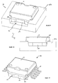
- Figure 1 Shown schematically in Figure 1 is a package having an exposed heat sink element as it appears immediately after forming the plastic case.
- the package is shown in a side view taken parallel to the direction of the leads, and partly in section in the left-hand portion of the figure. The cross-section is the obliquely hatched area.
- the package is generally denoted by 1 in that figure.
- That figure and the following ones illustrate by way of example a package of the DIP (Dual-In line Package) type, that is one having its leads projecting out from two opposite sides of the package body.
- DIP Dual-In line Package
- the semiconductor material die has been omitted from the sectional view.
- a plastic case, shown at 2 has a heat sink element 3 embedded therein such that only the bottom major surface 4 thereof, at the same level as the case bottom surface, will be exposed.
- a leadframe 5 is connected to the heat sink element 3 at the opposite side from the surface 4 by connecting means such as rivets or weldings, not shown in the sectional view.
- the leadframe is partly enclosed in the case 2, so that ends of its lead, denoted by 6 extending outside, to the left and right in the figure. Shown outside the case 2, getting out of the plane determined by the case side surface in view, is a support structure 7 of the leadframe interconnecting a number of leadframes, as explained hereinafter.
- Each heat sink element is obtained by shearing from a relatively thick sheet of metal, e.g. copper. From a thinner sheet, also typically of copper, a bearing structure is formed in the form of a strip and a series of leadframes, each including an assembly of narrow metal strips which are interconnected by transverse connecting lines and are intended to become the leads. To the bearing structure at each leadframe is connected a corresponding number of heat sink elements.
- a relatively thick sheet of metal e.g. copper.
- a bearing structure is formed in the form of a strip and a series of leadframes, each including an assembly of narrow metal strips which are interconnected by transverse connecting lines and are intended to become the leads.
- To the bearing structure at each leadframe is connected a corresponding number of heat sink elements.
- a corresponding number of dice are mounted integrally to this formed structure, such that each die locates at one leadframe/heat sink element structure.
- each die is connected, according to a standard technique, directly to the heat sink element without the leadframe interposed therebetween.
- the die is positioned in the central region of the heat sink element, isolated from the leads. Reference will be made in the following description to this case wherein the leadframe has no dedicated area for accommodating the die.
- the die is connected to the heat sink element either by soldering with an alloy such as tin/lead or by gluing with for example an epoxy glue.
- Another solution provides for the die being accommodated on a central portion of the corresponding leadframe, which is also connected to the heat sink element.
- Thin wires usually of gold or aluminum, are bonded with one end to dedicated metallized pads provided on the die surface where the integrated circuit is formed, and with the other end to the inward ends of the leads.
- each cavity is injected an electrically insulative material, in the molten state at a high temperature, which is to form the plastic body of the package.
- This material is typically a synthetic resin, e.g. an epoxy resin.
- Molding in the proper sense comprises the injection of the resin into the cavities. However, the molding process comprises several phases whereat the temperature is varied gradually to avoid cracking the semiconductor material that forms the die, or otherwise making the overall device unreliable.
- the term molding is used herein to denote all the operations carried out inside the mold cavity: melting the plastic material, letting it expand into the cavity and solidify.
- the plastic cases After an initial cooling step, and subsequent resin thermal curing steps to achieve thorough polymerization, the plastic cases will be completely formed, and the series of packages ready for removal from the mold.
- Figure 2 shows schematically a mold at a stage immediately preceding the molding step to form the package shown in the previous figure.
- the figure shows in particular a single mold cavity.
- a mold for the injection of resin is generally shown at 8. It comprises, in the common embodiment shown in the figure, an upper half-shell or top mold designated 8a, and a lower half-shell or bottom mold 8b. Both half molds have a corresponding hollow, and when the mold is closed, are arranged with their hollows facing each other to provide a single mold cavity whereinto the resin can be injected.
- the molten resin is injected through a gate type of inlet, designated 9 in Figure 2, formed in the mold, specifically in the bottom mold 8b, which has one end open into the mold cavity.
- the gate 9 has a substantially horizontal main axis. Its location is in any case such that the cavity can be filled even in its region at the extreme right in the figure, farthest from the resin entrance.
- the structure consisting of the heat sink element 3 and the leadframe 5 has been introduced for molding into the mold cavity, according to the configuration shown in the figure. Also shown in that figure is a die of a semiconductor material 10 fixed to the center of the top surface of the heat sink element 3 opposite from the major surface 4 to be left exposed.
- the leadframe 5 is located at the same level as the interface between the two half molds, and is positioned such that the terminating portions of the leads 6 are left outside the mold cavity.
- the mold 8 typically has one closure level only, when viewed in vertical cross-section, consisting of the surfaces at the interface of the two half molds and corresponding to the level of the leadframe 5. The presence of such a closure level is effective to make possible the introduction of the leadframe into the cavity in a easy way while allowing its outermost portions to remain outside.
- the heat sink element is located on the bottom of the mold cavity formed in the bottom mold 8b such that the bottom surface 4 will not be covered by the resin.
- the mold cavity has larger side dimensions than the heat sink element 5, and will therefore fully enclose it so as to keep the heat sink element 5 isolated laterally all around its perimeter.
- Both the bottom and top portions of the mold cavity have substantially the shape of a parallelepiped. Accordingly, the cavity shape for molding that type of package is particularly simple.
- the power package has a different structure from that shown.
- the heat sink element additionally to having a major surface exposed, will be partially extended sidewards out of the plastic case, from at least one of its sides.
- the heat sink element has two peripheral portions projecting from two opposed sides of the plastic case.
- Figure 3 is a perspective view of a known embodiment of a power package with the heat sink partially extended out of the plastic case.
- PSO package known as PSO
- the package is overall denoted by the reference numeral 11 and shown at the end of its manufacture, after bending the pins, ready to be soldered to an external electric circuit.
- the plastic case 2 partly encapsulates a heat sink element, generally denoted by 12 here, which, besides having its bottom surface exposed, extends sidewards out of the plastic case 2 in the direction denoted by y.
- a heat sink element generally denoted by 12 here, which, besides having its bottom surface exposed, extends sidewards out of the plastic case 2 in the direction denoted by y.
- the dimensions of the plastic case 2 exceed those of the corresponding sides of the heat sink element 12.
- the heat sink element 12 has in this example two peripheral portions, designated 13 in Figure 3, which symmetrically extend outwards.
- the top major surface 14, the side surface 15 lying in the x direction, and part of the side surfaces 16 parallel to the direction determined by the axis y are also exposed.
- the profile of the plastic case 2 and of the heat sink element 12 are determined by the particular conformation of the specific example.
- the leads, bent over to form the pins 17, are extended outside the plastic case 2 of the package 11 from opposite sides in the x direction, orthogonally to the direction along which the heat sink element 12 extends beyond the case 2.
- main cavity will be used in the following description to indicate that portion of the mold cavity which has the shape of the plastic case envelope without taking into account the presence of the heat sink element therein. Thus, it will commonly have a substantially parallelpipedic shape.
- the main mold cavity such as the mold cavity used in the example shown in Figure 2, typically results from the combination of an upper hollow formed in the top mold and a lower recess provided in the corresponding half-shell.
- the dimension of the main mold cavity along the y direction must be shorter than the length along y of the heat sink element 12.
- the mold considered overall to comprise a specific seat for the heat sink element, and in particular to provide a housing for the heat sink element which extends in the y direction outside the main mold cavity, and which is furthermore connected to the main mold cavity such that the plastic case can be formed around the heat sink element in the x direction.
- This housing is a blind hole, i.e. without side outlets, formed in the bottom portion of the mold.
- the molding technique provides for the mold to have for this purpose, additionally to a conventional first closure level corresponding to the leadframe, as in the simpler case previously discussed, a second closure level at the top major surface of the heat sink element.
- the aforementioned housing is provided at least below this level.
- Such a configuration may typically cause some drawbacks during the molding step. Specifically, problems may be encountered at the interface between the housing portions which are intended to receive the portion of the heat sink element outside the plastic case, and the main mold cavity. In fact at the second closure level, the mold sealing during the molding is specially critical. Particularly between the surfaces of the heat sink element which must be left exposed and said housing formed in the mold, the hermeticity is very difficult to achieve. Thus, during the molding step, the molten resin may partly leak out of the mold cavity in the y direction towards the most peripheral portions of the heat sink element. Over the related surfaces of the heat sink element, the leaking resin may result in the formation of flash, that is thin layers of plastic material which solidify on the external surfaces of the heat sink element.
- Figure 4 shows a schematical top view of the lower portion of a mold during the molding of the package shown in the previous figure. Both the leadframe and the semiconductor material die have been omitted, and only the heat sink element shown, for clarity reasons.
- the lower portion of the mold main cavity, denoted by 18, extends in the x direction sideways of the heat sink element 12 in connection with its central portion.
- the heat sink element 12 is disposed to have its peripheral portions 13 at the ends of a housing, denoted by 19, which is formed in the mold lower portion and extends substantially in the y direction beyond the mold main cavity 18.
- the upper closure of the housing 19 is determined by the upper structure of the mold, not shown in the figure.
- Figure 4a is an enlarged detail view of the portion enclosed within a broken line circle in Figure 4.
- a known solution to this problem provides for the use of blocking bars formed in the structure of the heat sink element at the peripheral portions thereof.
- the heat sink element/leadframe structure is formed integrally from a thick metal sheet, by shaping the heat sink element and then reducing the thickness at the sides and forming by shearing the leadframe.
- FIG. 5 A structure of this type is shown in Figure 5.
- the heavy outlined portion is the heat sink element 12, lighter lines being used to draw the leadframe 5.
- the leadframe 5 and heat sink element 12 form a mono-component and are joined to each other by blocking bars 20.
- These bars 20 of copper consist of side extensions of the peripheral portions 13 of the heat sink element 12 in the x direction. When the structure of Figure 5 is placed into the mold, the bars 20 substantially close the side channel for the resin flow indicated in Figure 4a.
- a further drawback of the known solution of Figure 5 is related to the formation of the mono-component heat sink/leadframe structure.
- the leadframe thickness cannot be less than a minimum value, if it is not to be distorted during its formation due to the weight of the heat sink element whose mass is far greater.
- Figure 6 shows schematically a vertical cross-section along the y direction through a mold made in accordance with that patent.
- Thrust elements denoted by 21, compress the heat sink element against the bottom of its housing.
- the alveolus 22 outside the heat sink element are filled with resin through suitable channels, not shown.
- Their width in the x direction is the same as that of the portions of the heat sink element which are to be left outside the plastic case.
- the plastic tips thus formed must then be removed, after taking the case out of the mold.
- This additional operation is critical especially with configurations like that shown in Figure 3 by way of example, wherein the peripheral portions of the heat sink element have the same width as the heat sink element, and substantially of the same order as the plastic case. In this instance, the plastic case may be cracked during that step.
- the solvent idea on which the present invention is based is founded on the consideration that it is possible to ensure, during the molding process, the hermeticity between the side surfaces of the heat sink element to be left outside the plastic case and the corresponding walls of the housing formed in the lower portion of the mold, while ensuring proper positioning of the heat sink element in its housing, by using a housing with inclined walls and by shaping the side surfaces of the heat sink element to match this inclination at least in the zone nearest the plastic case.
- a method of the type according to this invention provides for the formation of a plastic package for a power semiconductor electronic device with a partially exposed heat sink.
- the semiconductor electronic device is fully encapsulated within a plastic case and coupled thermally to a heat sink element.
- the latter has an exposed major surface and at least one peripheral portion extended outside the plastic case from at least one of its sides.
- the plastic case is formed by molding in a main cavity of a mold.
- the heat sink element has first been placed into a suitable housing provided in a lower portion of the mold, such that the major surface to be left exposed contacts the housing bottom. This housing also opens into the main cavity of the mold.
- the inclined side surfaces of the heat sink element when the mold is closed, the inclined side surfaces of the heat sink element, in its peripheral portion to be left outside the plastic case, are therefore pressed by the thrust means toward corresponding inclined walls of the housing.
- the compressive force exerted by said means and in a downward direction will have a component orthogonal to such surfaces.
- perfect temporary relative adhesion is ensured during the molding process of the side surfaces of the heat sink element to the walls of the housing in which it is located at least in the nearest zone to the mold main cavity, that is to the side of the plastic case whence the heat sink element extends. Accordingly, the hermeticity of the closure clamping of the mold is ensured even at the aforementioned second closure level by the method of this invention. In this way, bothersome leakouts of plastic material from the mold main cavity toward the peripheral portions of the heat sink element can be prevented.
- the housing for the heat sink element consists of a suitable portion of a through-going groove formed in the lower portion of the mold. According to this invention, it is indeed unnecessary to provide a blind hole for accommodating the heat sink element because the thrust elements together with the heat sink element will act as a barrier or side closure of the mold in the direction along which the heat sink element extends out of the case. The mold is, therefore, simpler to manufacture.
- each heat sink element is positioned with its central portion, to be left inside the plastic case, corresponding to widenings of the groove which will form the lower portion of the mold main cavity.
- the peripheral portion of the heat sink elements to be left outside the plastic case is properly inserted into the groove outside said widenings.
- the depths of the groove and the cavity are substantially equivalent, such that the rims of the recesses formed thereby are at the same level. In this way the lower portion of the mold can be formed by digging from the surface of the bottom mold to form both the groove and the lower portion of the cavity.
- the groove is straight and has inner side surfaces inclined through the entire groove length and has a plurality of widenings for accommodating a given number of heat sink elements positioned parallel and spaced apart from one another in the groove.
- the preferential method also provides for the heat sink elements to have inclined throughout the portion to be left outside the case those external side surfaces substantially orthogonal to the sides of the case whence they come out.
- a package for a power semiconductor electronic device comprises a plastic case to be formed by a molding process wherein at least one die of a semiconductor material is completely encapsulated which has an electronic circuit formed therein and is coupled thermally to a heat sink element having an exposed major surface and at least one peripheral portion extended out of the plastic case from at least one side thereof.
- at least side surfaces of said heat sink element extending out from said side of the plastic case form, at least in a zone adjacent to the case and in said peripheral portion, an angle substantially greater than zero with the direction of a normal line to said major surface of the heat sink element having a negative slope from outside.
- FIGS. 1 and 8 are vertical cross-section views of a mold, generally and schematically shown at 23, which embodies the principles of this invention.
- the cross-sections have been taken along directions, respectively orthogonal and parallel to the direction in which the heat sink element is extended out of the plastic case, as indicated by lines B-B and A-A, respectively, in Figure 8 and Figure 7.
- Figures 7 and 8 are parallel to the directions designated x and y, respectively.
- the figures show a single mold cavity for forming a single package, although the mold typically includes a plurality of cavities.
- the mold 23 comprises an upper half-shell or top mold 23a and a lower half-shell or bottom mold 23b. In either figures the mold is shown closed with the two half molds facing each other, as it appears typically during the molding step.
- An upper hollow and lower hollow formed in the two half molds 23a and 23b define, when the mold is closed, a mold main cavity 24 for forming the plastic case of the package.
- the two portions of the mold main cavity are marked off by an imaginary broken line between the two half molds.
- the heat sink element 25 is placed in a suitable housing, overall indicated at 26, which is formed in the lower portion of the mold 23, specifically in the bottom mold 23b.
- the bottom major surface 27 of the heat sink element is in contact with the bottom surface of the housing 26. The latter opens into the mold main cavity 24 from which it is extended outwards in the y direction, as shown in Figure 8.
- the heat sink element extends, by way of example only, out from two opposite sides of the mold main cavity and in a substantially symmetrical arrangement. However, it could be a different configuration, still remaining within the invention scope.
- the sidewalls of the housing 26 which are parallel to the y direction, that is the direction in which the heat sink element is to extended out of the plastic case, are inclined from the vertical direction, unlike conventional cases.
- these walls, indicated at 28 in the figure form an angle ⁇ with a normal direction, determined by the half lines N, to the major surfaces of the heat sink element 25, and specifically to the surface 27 or to the bottom of the housing, so as to have a positive slope from the housing interior.
- Shown at 29 in the figures are the side surfaces of the heat sink element 25 which are parallel to the y direction, to be partially enclosed within the plastic case.
- the portions of the side surfaces 29 of the heat sink element which are to be left outside the plastic case and facing said housing walls 28 are inclined, forming an angle substantially equal to ⁇ with the N direction.
- the heat sink element Prior to molding, the heat sink element must be positioned without being fixed in its housing to avoid mold wear problems and damaging the device during its removal from the mold at the end of the molding step.
- the heat sink element 25 is pushed down into the mold and caused to adhere on the inner walls in accordance with this invention during the mold closing.
- thrust means will engage from above with at least a part of the peripheral portions of the heat sink element 25 external to the mold main cavity 24 and contained within the housing 26.
- such thrust means consists of, as shown schematically in Figure 8, elements (notches) 30 jutting out of the top mold 23a and extending downwards at the side of the recess of the top mold 23a, and hence of the main mold cavity 24, and being adjacent thereto.
- the notches 30 exert a compressive force substantially downward on the peripheral portions of the heat sink element.
- the heat sink element 25, being made typically from a deformable material such as copper, undergoes a slight deformation at these portions.
- This compressive force according to this invention also applies a pressure to the side surfaces 29 of the heat sink element.
- Said force has, in fact, a non-zero component orthogonal to the latter because the direction of the force also forms an angle ⁇ with the surfaces 29.
- the latter are pressed at these portions against the corresponding inner walls 27 of the housing which are parallel to them.
- the strength of the compressive force exerted by the notches 30 is selected to cause the surfaces 29 to adhere to the walls 28.
- the barrier to the outflow of resin from the mold main cavity is provided by the combined actions of the notches down-pressing and of the heat sink element acting as a plug.
- the reliability of the resulting case is then ensured. Therefore during the package forming process no particularly complex and following steps of removing residual resin are needed. The process is, therefore, particularly simple, and the overall device packaging time is advantageously shortened.
- the angle ⁇ is selected illustratively to avoid difficulties in manufacturing the mold and heat sink element; it may be selected to be typically smaller than 30°.
- the housing 26 can be advantageously utilized as a guide in positioning the heat sink element 25 inside it. This can be seen as a self-aligning feature in the x direction since the heat sink element 25, if placed twisted by mistake, would automatically turn and regain its correct position. Due to this problem, prior processes required manual intervention or at least additional checking of the heat sink element for placing it in a proper position.
- the invention allows automatic machines of the pick-and-place type to be used which would pick and position heat sink elements without any further checking.
- the housing for the heat sink element need not be delimited in the y direction; this because of the apparatus configuration ensuring perfect closing of the mold cavities even in this direction.
- the two horizontal broken lines indicated at 32, at the level of the bottom surface 27 of the heat sink element 25, denote that the housing structure may be extended beyond the length of the heat sink element in the y direction along which it extends out of the mold main cavity.
- a method for forming a PSO type of package such as that illustrated in connection with the prior art of Figure 3.
- the package is of the dual-in-line type, with electric interconnecting pins coming out of the package from two opposed sides and orthogonally to the direction in which the heat sink element is extended out of the plastic case.
- Figure 9 shows a perspective view of a mold open at the end of the molding operation for the plastic case of the package.
- the mold is shown referring to a single device.
- Figure 10 shows a vertical cross-section taken in the orthogonal direction to that of outward extension of the heat sink element, namely the y direction of Figure 9.
- the mold is overall shown at 33, and in both figures only its lower portion 33b is in view.
- the plastic case 2 is partially inserted into the lower portion of the mold main cavity and projects upwardly from the bottom mold 33b.
- a groove 34 is provided in the bottom mold 33b which goes through the bottom mold 33b from one side to other.
- the groove 34 has a main axis along the direction in which the heat sink element 25 is to extend out of the plastic case 2, i.e. parallel to the y direction.
- the width of the groove 34 is equal to the dimension along x of the heat sink element 25.
- the walls of the groove 34 parallel to the y direction, indicated at 28' in these figures, are inclined, according to this invention, at an angle ⁇ from the normal N.
- an angle ⁇ around the 15° range was selected.
- the depth of the groove 34 is such that its bottom locates correspondingly to the bottom surface of the package. Its edge is at the level of the leadframe, that is of the separation line between the two half molds, so that the leads can be left outside the mold cavity. Essentially, its depth is the same as that of the lower main mold cavity.
- the lower portion of the mold main cavity forms a enlargement in the x direction of the groove 34 at the location where the heat sink element 25 is to be placed.
- the heat sink element is disposed such that its central portion, to be encapsulated within the plastic case, is in correspondence with said enlargement, and with its peripheral portions within the groove 34 but outside the enlargement.
- the side surfaces 28' of the heat sink element are correspondingly inclined at least inside the groove in the portions outside the plastic case, and in contact with the groove walls.
- the central portions of the side surfaces of the heat sink element are similarly arranged, since they are engaged in the groove, without contacting any walls, being faced the enlargement formed by the lower mold cavity.
- these central portions are not inclined but are orthogonal to the bottom major surface 27 of the heat sink element.
- peripheral surfaces of the plastic case, and correspondingly therewith the inner walls, not visible, of the mold cavity, are inclined as in the conventional structure for easy removal from the mold, independently of the objects of this invention.
- the through-going groove can accommodate a given number of heat sink elements, typically some tens of them, placed parallel.
- the groove 34 could contain about fifteen heat sink elements, and the bottom mold 33b was formed with several parallel through-going trenches.
- each groove 34 is formed from one side to another into a main surface of the bottom mold. It has the appearance of a hollow with inclined walls, having a single main axis and presenting a corresponding number of widenings, also parallel to one another and spaced apart at the locations where the heat sink elements 25 will be placed.
- the heat sink elements are typically placed into the groove simultaneously, after riveting them to a single metal strip which includes their respective lead frames.
- the heat sink elements could be placed into the groove sequentially, for a different process wherein the heat sinks are attached to the leadframes after being placed into the mold.
- the heat sink element 25 can be placed into the mold 33b in a particularly easy manner, in this preferential embodiment wherein the housing for the heat sink element is other than a blind hole.
- the groove represents a straight guide having possible the placement of each heat sink element may be laid in place by inserting it laterally of the mold through one of the two side mouths of the groove.
- the notches are formed on the upper portion, not shown in the figures, of the groove, and fit into the groove 34 upon closing the mold, to engage the portions of the heat sink element which lie outside the main cavity. It is on this account that the notches are formed laterally of the upper portion of the mold main cavity. Their width is substantially the same as that of the groove. For each mold cavity, a pair of notches are typically provided on opposing sides such that, between adjacent cavities, there will be two limited notches in the y direction. In an alternative embodiment, two notches of two adjacent cavities may be joined into a single, extended notch between the two adjacent cavities, adapted to be inserted inside the groove. Their height is such that their tips, with the mold closed, will not reach the bottom, but stop at the same level as the upper major surface of the underlying heat sink element.
- the mold structure and in particular that of its lower portion, is therefore particularly simple according to the preferential embodiment of this invention.
- this affords lower manufacturing costs than conventional molds.
- the mold needed to have a more complicated structure. Nowhere could an "open" configuration like that of our preferential embodiment with a through-going groove be used, since it was necessary to define a delimited area in the bottom mold for containing the plastic material.
- Figure 11 shows the package, overall indicated at 35, after its removal from the mold 33 and subsequent steps wherein the individual packages are separated from one another (the singulation step) by cutting the metal strip on which the series of lead frames are formed, and the leads are bent to form the pins 17.
- the heat sink element 25 has, in the peripheral portions 36 outside the plastic case 2, as shown in the figure, its side surfaces 29, parallel to the y direction, inclined from an orthogonal straight line to the major surfaces of the heat sink element with a negative outward slope.
- the portions of such surfaces inside the plastic case, not in view in Figure 11, are instead orthogonal to the major surfaces of the heat sink element 25.
- these central portions have a different, slightly smaller width than the outwardly extended portion.
- this invention has been particularly illustrated in connection with packages of the dual-in-line type, this invention may also be applied to packages having projecting pins from one side only of the plastic case, that is of the single-in-line type.
- the pins could project for equal effect either orthogonal or parallel to the direction in which the plastic case is extended outwardly, both in the dual-in-line version illustrated herein and the single-in-line version.
- the through-going groove illustrated in the preferential embodiment could be non-straight and follow a different pattern, but always including corresponding to each heat sink element portions adapted to accommodate, for example, a single heat sink element. These portions may typically have a main axial direction parallel to the direction along which the heat sink element extends outwards from the plastic case.
- the through-going groove may have the overall pattern of a polygonal line.
- each through-going groove may vary to suit particular applications. In the extreme, each through-going groove could accommodate only one heat sink element.
- the depth of the groove described by the figures is greater than the height of the heat sink element it is to receive, but its functionality would not change even if a particular applications required a groove of smaller or equal depth, with the heat sink element extending upwardly toward the upper portion of the mold main cavity.
- the side surfaces of the heat sink element lying parallel to the y direction could be, in a different embodiment, inclined also at their central portion embedded within the plastic case, in a simplified, easily manufactured construction. In the extreme, the side surfaces parallel to the x direction and completely outside the plastic case could also be inclined, and still fall within the scope of the present invention.
- the heat sink element should extend out of the case in a symmetrical way is no strict requirement, nor is that it should be symmetrical.
- the heat sink element may have different shapes and dimensions also in the respect of the plastic case, and its width along x could be the same as that of the case, for example.
- the figures described relate to the typical instance of the heat sink element being extended outside the plastic case from two opposite sides.
- the heat sink element could come out from one side only, so being anyway determined a y direction along which the walls of its housing would be inclined.
- side surfaces of the heat sink element could jut out of the plastic case in a direction different than a direction orthogonal to the respective side of the case.
- the housing would no longer have a single main direction, but in accordance with this invention its walls would have to be inclined at least in each portion in contact with side surfaces, also correspondingly inclined, of the heat sink element, near and outside the plastic case.
Description
- This invention relates to a method for forming a plastic package for an electronic device having an heat sink exposed and which extends sideways out of the case, and a mold for use with the method.
- The method of forming a plastic package for a power semiconductor electronic device to be encapsulated within a plastic case and to be coupled thermally to a heat sink element having a major surface exposed and at least one peripheral portion extending outwards from at least one side of the plastic case is of the type wherein it provide for forming the plastic case of the package be molding inside a main cavity of a mold after positioning said heat sink element with said major surface in contact with the bottom of a suitable housing provided in a lower portion of said mold which opens into said main cavity of the mold.
- Reference will be made hereinafter, by way of example and not of limitation, in particular to PSO (Plastic Small Outline) packages of the dual-in-line type. More specifically we will refer to packages intended for example for automotive applications, that is for installation on device equipping motor cars.
- As is well known, semiconductor electronic devices comprise an electronic circuit formed in a small plate or "die" of a semiconductor material with a surface area dimension of a few square millimeters. Typically, the electronic circuit is integrated monolithically on a major surface of the die. The die is protected thermally and mechanically by encapsulating it within a package. Reference will be made in particular to plastic packages.
- Such devices require suitable means of support and electrical interconnection for electrically connecting them to external circuits. For this purpose, a conductive lead frame, consisting of a thin wrought metal plate, comprises a plurality of narrow strips which represent electric connectors or leads having one end connected electrically to the integrated circuit. At the other side, the peripheral ends of the leads extend outwards from the package body for allowing electric interconnection of the device. On completion of the package forming process, the peripheral terminations of the leads are bent and forms respective pins for mounting the package, typically to a printed electronic board.
- In the instance of integrated power circuits, to whom we refer herein, that is devices which are liable to produce a relatively large amount of heat for example due either to their high component density and/or number, or because intended for operation with large currents, reference is commonly made to so-called power packages. By this term, we are indicating that the device can dissipate heat by some means of its own.
- In this instance, in fact, the structure supporting the die also serves a heat dissipating function, and further includes a heat sink element or slug for this purpose. The die is coupled thermally to the heat sink element to transfer outside the heat generated during its operation.
- The heat sink element is just a metallic element or in any case a good heat conductor whose mass is definitely larger than that of the die or of the electronic device. It usually is in the form of a copper plate of non negligible thickness.
- In a typical realisation, the semiconductor material die is mounted directly on a major surface of the heat sink element so that the surface whereon the circuit is formed remains free. The lead frame is attached to the heat sink element too.
- Power packages are typically formed such that the heat sink element, embedded in the plastic package body, has exposed, that is uncovered by plastic material, its major surface non contacting the die. This configuration promotes the transfer of heat from the device to outside the package. To improve the dissipation of heat, advantageously this exposed surface of the heat sink element may optionally be in contact with an external heat sink of even larger size and mass, and accordingly providing enhanced heat dissipation. Reference will be made throughout the following description and the drawings to the case in which the exposed major surface of the heat sink element is the bottom surface, that is located on the same side as the bending of the pins. The external heat sink is typically formed by the structure itself to which the case is soldered. Alternatively, could be exposed the top major surface of the heat sink element, to which a suitable external heat sink may be attached.
- Typically in a power package, the heat sink element has only one major surface exposed, the other major surface and all the side surfaces being insulated, that is covered with the plastic material of the case. Throughout the following description, side surfaces are those surfaces of the heat sink element which connect perimetrically the two major surfaces substantially parallel to each other.
- Shown schematically in Figure 1 is a package having an exposed heat sink element as it appears immediately after forming the plastic case. The package is shown in a side view taken parallel to the direction of the leads, and partly in section in the left-hand portion of the figure. The cross-section is the obliquely hatched area. The package is generally denoted by 1 in that figure.
- That figure and the following ones illustrate by way of example a package of the DIP (Dual-In line Package) type, that is one having its leads projecting out from two opposite sides of the package body.
- For clarity and simplicity of illustration, the semiconductor material die has been omitted from the sectional view.
- A plastic case, shown at 2, has a
heat sink element 3 embedded therein such that only the bottom major surface 4 thereof, at the same level as the case bottom surface, will be exposed. Aleadframe 5 is connected to theheat sink element 3 at the opposite side from the surface 4 by connecting means such as rivets or weldings, not shown in the sectional view. The leadframe is partly enclosed in thecase 2, so that ends of its lead, denoted by 6 extending outside, to the left and right in the figure. Shown outside thecase 2, getting out of the plane determined by the case side surface in view, is asupport structure 7 of the leadframe interconnecting a number of leadframes, as explained hereinafter. - For a better understanding of the present invention aspects, the usual steps of a process for forming a conventional package with exposed heat sink will now be described briefly.
- Each heat sink element is obtained by shearing from a relatively thick sheet of metal, e.g. copper. From a thinner sheet, also typically of copper, a bearing structure is formed in the form of a strip and a series of leadframes, each including an assembly of narrow metal strips which are interconnected by transverse connecting lines and are intended to become the leads. To the bearing structure at each leadframe is connected a corresponding number of heat sink elements.
- A corresponding number of dice are mounted integrally to this formed structure, such that each die locates at one leadframe/heat sink element structure. As mentioned above and described, for example, in European Patent Application 545007 of this Applicant, each die is connected, according to a standard technique, directly to the heat sink element without the leadframe interposed therebetween. The die is positioned in the central region of the heat sink element, isolated from the leads. Reference will be made in the following description to this case wherein the leadframe has no dedicated area for accommodating the die. In this instance, the die is connected to the heat sink element either by soldering with an alloy such as tin/lead or by gluing with for example an epoxy glue. Alternatively, another solution provides for the die being accommodated on a central portion of the corresponding leadframe, which is also connected to the heat sink element. Thin wires, usually of gold or aluminum, are bonded with one end to dedicated metallized pads provided on the die surface where the integrated circuit is formed, and with the other end to the inward ends of the leads.
- Subsequently, the strip with the dice mounted thereon is placed into a mold having cavities corresponding to the single devices for forming their corresponding plastic cases. It is provided that each cavity is injected an electrically insulative material, in the molten state at a high temperature, which is to form the plastic body of the package. This material is typically a synthetic resin, e.g. an epoxy resin.
- Molding in the proper sense comprises the injection of the resin into the cavities. However, the molding process comprises several phases whereat the temperature is varied gradually to avoid cracking the semiconductor material that forms the die, or otherwise making the overall device unreliable. The term molding is used herein to denote all the operations carried out inside the mold cavity: melting the plastic material, letting it expand into the cavity and solidify.
- After an initial cooling step, and subsequent resin thermal curing steps to achieve thorough polymerization, the plastic cases will be completely formed, and the series of packages ready for removal from the mold.
- Figure 2 shows schematically a mold at a stage immediately preceding the molding step to form the package shown in the previous figure. The figure shows in particular a single mold cavity.
- A mold for the injection of resin is generally shown at 8. It comprises, in the common embodiment shown in the figure, an upper half-shell or top mold designated 8a, and a lower half-shell or
bottom mold 8b. Both half molds have a corresponding hollow, and when the mold is closed, are arranged with their hollows facing each other to provide a single mold cavity whereinto the resin can be injected. - The molten resin is injected through a gate type of inlet, designated 9 in Figure 2, formed in the mold, specifically in the
bottom mold 8b, which has one end open into the mold cavity. The gate 9 has a substantially horizontal main axis. Its location is in any case such that the cavity can be filled even in its region at the extreme right in the figure, farthest from the resin entrance. - The structure consisting of the
heat sink element 3 and theleadframe 5 has been introduced for molding into the mold cavity, according to the configuration shown in the figure. Also shown in that figure is a die of a semiconductor material 10 fixed to the center of the top surface of theheat sink element 3 opposite from the major surface 4 to be left exposed. - As can be seen, the
leadframe 5 is located at the same level as the interface between the two half molds, and is positioned such that the terminating portions of theleads 6 are left outside the mold cavity. Thus, for forming such a package, themold 8 typically has one closure level only, when viewed in vertical cross-section, consisting of the surfaces at the interface of the two half molds and corresponding to the level of theleadframe 5. The presence of such a closure level is effective to make possible the introduction of the leadframe into the cavity in a easy way while allowing its outermost portions to remain outside. - The heat sink element is located on the bottom of the mold cavity formed in the
bottom mold 8b such that the bottom surface 4 will not be covered by the resin. On the other hand the mold cavity has larger side dimensions than theheat sink element 5, and will therefore fully enclose it so as to keep theheat sink element 5 isolated laterally all around its perimeter. - Both the bottom and top portions of the mold cavity have substantially the shape of a parallelepiped. Accordingly, the cavity shape for molding that type of package is particularly simple.
- However, for certain applications, the power package has a different structure from that shown. For several necessities, the heat sink element, additionally to having a major surface exposed, will be partially extended sidewards out of the plastic case, from at least one of its sides. For example, the heat sink element has two peripheral portions projecting from two opposed sides of the plastic case.
- Thus, such packages also have exposed part of the other major surface and of the side surfaces of the heat sink element at such peripheral portions. This description will make reference to this type of package.
- Figure 3 is a perspective view of a known embodiment of a power package with the heat sink partially extended out of the plastic case. Reference will be made herein, by way of example, to a package known as PSO, of the type typically employed for automotive applications.
- The package is overall denoted by the reference numeral 11 and shown at the end of its manufacture, after bending the pins, ready to be soldered to an external electric circuit.
- As shown in the figure, the
plastic case 2 partly encapsulates a heat sink element, generally denoted by 12 here, which, besides having its bottom surface exposed, extends sidewards out of theplastic case 2 in the direction denoted by y. On the contrary in the orthogonal x direction, the dimensions of theplastic case 2 exceed those of the corresponding sides of theheat sink element 12. - In particular, the
heat sink element 12 has in this example two peripheral portions, designated 13 in Figure 3, which symmetrically extend outwards. In theseportions 13, the topmajor surface 14, theside surface 15 lying in the x direction, and part of the side surfaces 16 parallel to the direction determined by the axis y are also exposed. - The profile of the
plastic case 2 and of theheat sink element 12 are determined by the particular conformation of the specific example. - The leads, bent over to form the
pins 17, are extended outside theplastic case 2 of the package 11 from opposite sides in the x direction, orthogonally to the direction along which theheat sink element 12 extends beyond thecase 2. - For forming the plastic case of a package of this type, a mold must be used which has a more complex molding cavity than that shown in the previous Figure 2.
- The term main cavity will be used in the following description to indicate that portion of the mold cavity which has the shape of the plastic case envelope without taking into account the presence of the heat sink element therein. Thus, it will commonly have a substantially parallelpipedic shape. The main mold cavity, such as the mold cavity used in the example shown in Figure 2, typically results from the combination of an upper hollow formed in the top mold and a lower recess provided in the corresponding half-shell.
- In this case, however, the dimension of the main mold cavity along the y direction must be shorter than the length along y of the
heat sink element 12. Thus, it will be necessary for the mold considered overall to comprise a specific seat for the heat sink element, and in particular to provide a housing for the heat sink element which extends in the y direction outside the main mold cavity, and which is furthermore connected to the main mold cavity such that the plastic case can be formed around the heat sink element in the x direction. This housing is a blind hole, i.e. without side outlets, formed in the bottom portion of the mold. - The molding technique provides for the mold to have for this purpose, additionally to a conventional first closure level corresponding to the leadframe, as in the simpler case previously discussed, a second closure level at the top major surface of the heat sink element. The aforementioned housing is provided at least below this level.
- Such a configuration may typically cause some drawbacks during the molding step. Specifically, problems may be encountered at the interface between the housing portions which are intended to receive the portion of the heat sink element outside the plastic case, and the main mold cavity. In fact at the second closure level, the mold sealing during the molding is specially critical. Particularly between the surfaces of the heat sink element which must be left exposed and said housing formed in the mold, the hermeticity is very difficult to achieve. Thus, during the molding step, the molten resin may partly leak out of the mold cavity in the y direction towards the most peripheral portions of the heat sink element. Over the related surfaces of the heat sink element, the leaking resin may result in the formation of flash, that is thin layers of plastic material which solidify on the external surfaces of the heat sink element.
- To illustrate this problem, Figure 4 shows a schematical top view of the lower portion of a mold during the molding of the package shown in the previous figure. Both the leadframe and the semiconductor material die have been omitted, and only the heat sink element shown, for clarity reasons.
- The lower portion of the mold main cavity, denoted by 18, extends in the x direction sideways of the
heat sink element 12 in connection with its central portion. Theheat sink element 12 is disposed to have itsperipheral portions 13 at the ends of a housing, denoted by 19, which is formed in the mold lower portion and extends substantially in the y direction beyond the moldmain cavity 18. The upper closure of thehousing 19 is determined by the upper structure of the mold, not shown in the figure. - Figure 4a is an enlarged detail view of the portion enclosed within a broken line circle in Figure 4.
- As can be seen, it is impossible to arrange for perfect adhesion of the portions of the side surfaces 16 of the heat sink element that are to stay out of the case to the walls of the
housing 19. To indeed ensure proper positioning of theheat sink element 12 in thehousing 19 with no cracking risk, the latter is formed with its width along x in theportions 13 slightly smaller than that of the cavity which forms the housing. Thus, a passage channel on the order of a few microns is left at theportions 13 side. An arrow indicates in the figure a flow direction of a resin leak from the mold main cavity toward thehousing 19. Upon solidification of the resin, thin resin layers will form on the surfaces of theportion 13. - For the device to operate properly, an additional flashes removing step must be provided after molding. But those resin flashes are very difficult to remove because of their position.
- On the other hand known are molds whose inner shape presents into the cavity elements which push the metal slug against the bottom of the housing where it is placed, so as to improve the adhesion of the heat sink element to the mold. However, not even this configuration is appropriate to prevent resin formations on the exposed side surfaces of the heat sink element, although it ensures good adhesion of the housing bottom to the bottom surface of the heat sink element.
- A known solution to this problem provides for the use of blocking bars formed in the structure of the heat sink element at the peripheral portions thereof. To this aim, the heat sink element/leadframe structure is formed integrally from a thick metal sheet, by shaping the heat sink element and then reducing the thickness at the sides and forming by shearing the leadframe.
- A structure of this type is shown in Figure 5. The heavy outlined portion is the
heat sink element 12, lighter lines being used to draw theleadframe 5. As shown in the figure, theleadframe 5 andheat sink element 12 form a mono-component and are joined to each other by blockingbars 20. Thesebars 20 of copper consist of side extensions of theperipheral portions 13 of theheat sink element 12 in the x direction. When the structure of Figure 5 is placed into the mold, thebars 20 substantially close the side channel for the resin flow indicated in Figure 4a. - On completion of the molding step the
bars 20 must be removed to separate theheat sink element 12 along the broken lines in the figure. However, this additional operation renders the process critical because cracks may occur at the side extensions due to inaccuracies of the parting apparatus, which requires appropriate calibration. - A further drawback of the known solution of Figure 5 is related to the formation of the mono-component heat sink/leadframe structure. The leadframe thickness cannot be less than a minimum value, if it is not to be distorted during its formation due to the weight of the heat sink element whose mass is far greater.
- In addition, with this known solution, the mold must be given quite a complex configuration in order to accommodate the mono-component structure.
- While reliability and repeatability of a package thus formed can be improved, still the formation of resin flashes cannot be prevented altogether.
- A further known solution is disclosed in US Patent 5,445,995 to the same assignee. The mold is modified there to allow the resin to flow freely further outwards the peripheral portions of the heat sink element along the y direction into suitable alveolus.
- Figure 6 shows schematically a vertical cross-section along the y direction through a mold made in accordance with that patent. Thrust elements, denoted by 21, compress the heat sink element against the bottom of its housing. As shown, the
alveolus 22 outside the heat sink element are filled with resin through suitable channels, not shown. Their width in the x direction is the same as that of the portions of the heat sink element which are to be left outside the plastic case. - The plastic tips thus formed must then be removed, after taking the case out of the mold. This additional operation is critical especially with configurations like that shown in Figure 3 by way of example, wherein the peripheral portions of the heat sink element have the same width as the heat sink element, and substantially of the same order as the plastic case. In this instance, the plastic case may be cracked during that step.
- Thus, it is impossible to form a package which will be free from resin residues on the exposed surfaces of the heat sink element, without this being accompanied by drawbacks.
- The following documents EP0539095; US5445995; patent abstract of Japan JP04 116942; Ehnert A et al "A new surface mount power package" 7 march 1993, Proceedings of the annual applied power electronic conference and exposition (APEC), pages 380-384; DE1944098 ; Patent Abstract of Japan JP06061400; and EP545007 of the same applicant describe other power packages configurations.
- They underlying problem of this invention is to provide a method whereby can be formed, by only the molding process without the need of additional steps, a plastic package with an heat sink exposed and having portions extending peripherally from the plastic case kept free from resin leakouts.
- Furthermore the mold used and the conformation of the heat sink element/leadframe structure should be particularly simple.
- The solvent idea on which the present invention is based is founded on the consideration that it is possible to ensure, during the molding process, the hermeticity between the side surfaces of the heat sink element to be left outside the plastic case and the corresponding walls of the housing formed in the lower portion of the mold, while ensuring proper positioning of the heat sink element in its housing, by using a housing with inclined walls and by shaping the side surfaces of the heat sink element to match this inclination at least in the zone nearest the plastic case.
- A method of the type according to this invention provides for the formation of a plastic package for a power semiconductor electronic device with a partially exposed heat sink. The semiconductor electronic device is fully encapsulated within a plastic case and coupled thermally to a heat sink element. The latter has an exposed major surface and at least one peripheral portion extended outside the plastic case from at least one of its sides. The plastic case is formed by molding in a main cavity of a mold. The heat sink element has first been placed into a suitable housing provided in a lower portion of the mold, such that the major surface to be left exposed contacts the housing bottom. This housing also opens into the main cavity of the mold.
- According to this invention are provided the following steps:
- forming said heat sink element such that at least side surfaces jutting out of said side of the plastic case are, at least in a zone adjacent to said side and in said peripheral portion, inclined to form an angle substantially greater than zero with a normal line to said major surface, so as to have a negative slope from outside;
- correspondingly forming said housing such that its inner walls facing said side surfaces of the heat sink element are inclined, at least in said zone, to form an angle substantially equal to said angle with said normal line, with a positive slope from the housing interior; and
- providing thrust means which, when the mold is closed, is engaged from above with at least part of said peripheral portion of the heat sink element to exert thereon a compressive force having its direction substantially toward the housing bottom and which is effective to hermetically seal temporarily in said zone adjacent to said side of the plastic case said side surfaces of the heat sink element and said inner walls of the housing.
- Advantageously, when the mold is closed, the inclined side surfaces of the heat sink element, in its peripheral portion to be left outside the plastic case, are therefore pressed by the thrust means toward corresponding inclined walls of the housing. In fact, by having both such side surfaces and such walls inclined, the compressive force exerted by said means and in a downward direction will have a component orthogonal to such surfaces. Thus, perfect temporary relative adhesion is ensured during the molding process of the side surfaces of the heat sink element to the walls of the housing in which it is located at least in the nearest zone to the mold main cavity, that is to the side of the plastic case whence the heat sink element extends. Accordingly, the hermeticity of the closure clamping of the mold is ensured even at the aforementioned second closure level by the method of this invention. In this way, bothersome leakouts of plastic material from the mold main cavity toward the peripheral portions of the heat sink element can be prevented.
- The underlying technical problem of this invention is solved by a method of forming a plastic package with a peripherally extended heat sink of the type indicated above and defined in the characterizing portions of Claim 1 and foll..
- Preferably, according to this invention, the housing for the heat sink element consists of a suitable portion of a through-going groove formed in the lower portion of the mold. According to this invention, it is indeed unnecessary to provide a blind hole for accommodating the heat sink element because the thrust elements together with the heat sink element will act as a barrier or side closure of the mold in the direction along which the heat sink element extends out of the case. The mold is, therefore, simpler to manufacture.
- Furthermore, each heat sink element is positioned with its central portion, to be left inside the plastic case, corresponding to widenings of the groove which will form the lower portion of the mold main cavity. The peripheral portion of the heat sink elements to be left outside the plastic case is properly inserted into the groove outside said widenings. Advantageously, the depths of the groove and the cavity are substantially equivalent, such that the rims of the recesses formed thereby are at the same level. In this way the lower portion of the mold can be formed by digging from the surface of the bottom mold to form both the groove and the lower portion of the cavity.
- In a preferred embodiment, the groove is straight and has inner side surfaces inclined through the entire groove length and has a plurality of widenings for accommodating a given number of heat sink elements positioned parallel and spaced apart from one another in the groove. The preferential method also provides for the heat sink elements to have inclined throughout the portion to be left outside the case those external side surfaces substantially orthogonal to the sides of the case whence they come out.
- The technical problem is also solved by a mold as previously indicated and defined in the characterizing portions of
Claims 8 and foll.. - In addition, a package for a power semiconductor electronic device comprises a plastic case to be formed by a molding process wherein at least one die of a semiconductor material is completely encapsulated which has an electronic circuit formed therein and is coupled thermally to a heat sink element having an exposed major surface and at least one peripheral portion extended out of the plastic case from at least one side thereof. According to this invention, at least side surfaces of said heat sink element extending out from said side of the plastic case form, at least in a zone adjacent to the case and in said peripheral portion, an angle substantially greater than zero with the direction of a normal line to said major surface of the heat sink element having a negative slope from outside.
- The features and advantages of the method according to this invention will be apparent from the following description of an embodiment thereof, given by way of example and not of limitation with reference to the accompanying drawings.
- In the drawings:
- Figure 1 is a side view showing schematically a plastic package with exposed heat sink of a known type, which does not extend sidewards out of the plastic case;
- Figure 2 illustrates the step of molding the package shown in the preceding figure;
- Figure 3 is a perspective view of a plastic package of a known type having a heat sink element partially extended peripherally out of the plastic case;
- Figure 4 is a plan view showing the molding step according to a conventional technique for forming the package of Figure 3, and Figure 4a is an enlarged view thereof highlighting a drawback of such technique;
- Figure 5 shows a leadframe/heat sink element structure according to a first known embodiment for obviating the illustrated drawback;
- Figure 6 illustrates a method for forming a package with a heat sink partially extended out of the plastic case, according to a second known solution;
- Figures 7 and 8 are sectional views taken along two lines orthogonal to each other, respectively, which illustrate a scheme for an apparatus for use with the molding method of this invention;
- Figure 9 shows in perspective the lower portion of a mold open at the end of the molding step, according to one embodiment of this invention;
- Figure 10 is a sectional side view of the previous figure taken orthogonally to the groove;
- Figure 11 is a perspective view of a plastic package obtained in accordance with the illustrated embodiment of this invention.
- Referring to Figures 7 and 8, a scheme is shown which is illustrative of a method according to this invention and is visible an apparatus for forming a plastic package with a heat sink partially extended out of the case.
- The figures are vertical cross-section views of a mold, generally and schematically shown at 23, which embodies the principles of this invention. The cross-sections have been taken along directions, respectively orthogonal and parallel to the direction in which the heat sink element is extended out of the plastic case, as indicated by lines B-B and A-A, respectively, in Figure 8 and Figure 7. In particular, referring to the preceding figures, Figures 7 and 8 are parallel to the directions designated x and y, respectively.
- The figures show a single mold cavity for forming a single package, although the mold typically includes a plurality of cavities.
- The
mold 23 comprises an upper half-shell ortop mold 23a and a lower half-shell orbottom mold 23b. In either figures the mold is shown closed with the two half molds facing each other, as it appears typically during the molding step. - An upper hollow and lower hollow formed in the two
half molds main cavity 24 for forming the plastic case of the package. In the figures, the two portions of the mold main cavity are marked off by an imaginary broken line between the two half molds. - Only the heat sink element, as indicated at 25, has been drawn inside the mold with the other parts needed to form the package omitted for simplicity because conventional in both construction and position.
- The
heat sink element 25 is placed in a suitable housing, overall indicated at 26, which is formed in the lower portion of themold 23, specifically in thebottom mold 23b. The bottommajor surface 27 of the heat sink element is in contact with the bottom surface of thehousing 26. The latter opens into the moldmain cavity 24 from which it is extended outwards in the y direction, as shown in Figure 8. - In this schematical representation, the heat sink element extends, by way of example only, out from two opposite sides of the mold main cavity and in a substantially symmetrical arrangement. However, it could be a different configuration, still remaining within the invention scope.
- In accordance with this invention and as shown in Figure 7, the sidewalls of the
housing 26 which are parallel to the y direction, that is the direction in which the heat sink element is to extended out of the plastic case, are inclined from the vertical direction, unlike conventional cases. In other words, these walls, indicated at 28 in the figure, form an angle α with a normal direction, determined by the half lines N, to the major surfaces of theheat sink element 25, and specifically to thesurface 27 or to the bottom of the housing, so as to have a positive slope from the housing interior. Shown at 29 in the figures are the side surfaces of theheat sink element 25 which are parallel to the y direction, to be partially enclosed within the plastic case. Correspondingly to the slope of theinner walls 28 of the housing, the portions of the side surfaces 29 of the heat sink element which are to be left outside the plastic case and facing saidhousing walls 28 are inclined, forming an angle substantially equal to α with the N direction. - In the figure, the side surfaces 29 of the heat sink element and the
walls 28 of thehousing 26 have been drawn coincident for simplicity. However, as previously described in connection with the known solution, for proper positioning of theheat sink element 25 within its housing 26 a minimal gap on the order of a few microns should be allowed between the two surfaces. - Prior to molding, the heat sink element must be positioned without being fixed in its housing to avoid mold wear problems and damaging the device during its removal from the mold at the end of the molding step.
- The
heat sink element 25 is pushed down into the mold and caused to adhere on the inner walls in accordance with this invention during the mold closing. - For the purpose, when the mold is closed, thrust means will engage from above with at least a part of the peripheral portions of the
heat sink element 25 external to the moldmain cavity 24 and contained within thehousing 26. Preferably, such thrust means consists of, as shown schematically in Figure 8, elements (notches) 30 jutting out of thetop mold 23a and extending downwards at the side of the recess of thetop mold 23a, and hence of themain mold cavity 24, and being adjacent thereto. Thenotches 30 exert a compressive force substantially downward on the peripheral portions of the heat sink element. Theheat sink element 25, being made typically from a deformable material such as copper, undergoes a slight deformation at these portions. - In particular, the overall effect is that of sealing. This compressive force according to this invention also applies a pressure to the side surfaces 29 of the heat sink element. Said force has, in fact, a non-zero component orthogonal to the latter because the direction of the force also forms an angle α with the
surfaces 29. The latter are pressed at these portions against the correspondinginner walls 27 of the housing which are parallel to them. The strength of the compressive force exerted by thenotches 30 is selected to cause thesurfaces 29 to adhere to thewalls 28. - Perfect adhesion is ensured in this way during the molding step, between the side surfaces of the heat sink element outside the plastic case and the facing walls of the housing, that is in the most critical region as regards hermeticity. Thus, leakouts of plastic material from the mold main cavity onto the surfaces of the heat sink element inside the housing are prevented.
- The barrier to the outflow of resin from the mold main cavity is provided by the combined actions of the notches down-pressing and of the heat sink element acting as a plug.
- It should be considered that it is necessary according to this invention that such actions be exerted near the zones where the side surfaces of the heat sink element extend out of the plastic case, that is close to the mold main cavity. It is in such regions that the housing walls and corresponding side surfaces have to be inclined. On the other hand the shape of the housing outside such zones is not among the main objectives of the present invention.
- In accordance with this invention, the reliability of the resulting case is then ensured. Therefore during the package forming process no particularly complex and following steps of removing residual resin are needed. The process is, therefore, particularly simple, and the overall device packaging time is advantageously shortened.
- On the other hand no steps additional to the molding are intrinsically contemplated, like removing metal or plastic parts as is done in the known processes previously described, because the mold is already adapted to obtain the package in its finished form. This avoids the need for dedicated equipments sometimes expensive. Furthermore, the plastic case integrity is guarded by keeping it away from the risk of cracking or suffering any damage during such additional steps.
- According to this invention, the angle α is selected illustratively to avoid difficulties in manufacturing the mold and heat sink element; it may be selected to be typically smaller than 30°.
- The side surfaces of the heat sink element, indicated at 31 in Figures 7 and 8, which lie orthogonal to the
surfaces 29, that is along the x direction, completely outside the plastic case, could remain conventionally vertical for the purposes of this invention. In other words, they form a substantially zero angle with the straight line N. In this way, the manufacture of the heat sink element is advantageously simplified. - Notice that by having the
walls 28 of the housing inclined similarly to thesurfaces 29 of the heat sink element, thehousing 26 can be advantageously utilized as a guide in positioning theheat sink element 25 inside it. This can be seen as a self-aligning feature in the x direction since theheat sink element 25, if placed twisted by mistake, would automatically turn and regain its correct position. Due to this problem, prior processes required manual intervention or at least additional checking of the heat sink element for placing it in a proper position. - Thus, the invention allows automatic machines of the pick-and-place type to be used which would pick and position heat sink elements without any further checking.
- Notice that according to this invention the housing for the heat sink element need not be delimited in the y direction; this because of the apparatus configuration ensuring perfect closing of the mold cavities even in this direction. In Figure 8, the two horizontal broken lines indicated at 32, at the level of the
bottom surface 27 of theheat sink element 25, denote that the housing structure may be extended beyond the length of the heat sink element in the y direction along which it extends out of the mold main cavity. - In this sense, a preferential embodiment of this invention is shown in Figures 9 and 10. In these figures, the same reference numerals as in the previous figures have been retained to denote equal or similarly functioning parts and elements.
- In this example, reference is made in particular to a method for forming a PSO type of package, such as that illustrated in connection with the prior art of Figure 3. The package is of the dual-in-line type, with electric interconnecting pins coming out of the package from two opposed sides and orthogonally to the direction in which the heat sink element is extended out of the plastic case.
- Figure 9 shows a perspective view of a mold open at the end of the molding operation for the plastic case of the package. In particular, the mold is shown referring to a single device. Figure 10 shows a vertical cross-section taken in the orthogonal direction to that of outward extension of the heat sink element, namely the y direction of Figure 9.
- The mold is overall shown at 33, and in both figures only its lower portion 33b is in view. On its interior, the
plastic case 2 is partially inserted into the lower portion of the mold main cavity and projects upwardly from the bottom mold 33b. - Has been omitted for simplicity the leadframe which locates at the level of the upper surface of the top mold 33b having, in this example, connecting leads which are partially extended outside the plastic case in the x direction, from both sides.
- According to this preferential embodiment of the invention, to accommodate the
heat sink element 25, agroove 34 is provided in the bottom mold 33b which goes through the bottom mold 33b from one side to other. Thegroove 34 has a main axis along the direction in which theheat sink element 25 is to extend out of theplastic case 2, i.e. parallel to the y direction. The width of thegroove 34 is equal to the dimension along x of theheat sink element 25. - The walls of the
groove 34 parallel to the y direction, indicated at 28' in these figures, are inclined, according to this invention, at an angle α from the normal N. In a preferential embodiment, an angle α around the 15° range was selected. - The depth of the
groove 34 is such that its bottom locates correspondingly to the bottom surface of the package. Its edge is at the level of the leadframe, that is of the separation line between the two half molds, so that the leads can be left outside the mold cavity. Essentially, its depth is the same as that of the lower main mold cavity. Theheat sink element 25, which in the package commonly has its top surface at a lower level than the leadframe, is fully contained within thegroove 34, its height being smaller than the groove depth. - The lower portion of the mold main cavity forms a enlargement in the x direction of the
groove 34 at the location where theheat sink element 25 is to be placed. In particular, the heat sink element is disposed such that its central portion, to be encapsulated within the plastic case, is in correspondence with said enlargement, and with its peripheral portions within thegroove 34 but outside the enlargement. - The side surfaces 28' of the heat sink element are correspondingly inclined at least inside the groove in the portions outside the plastic case, and in contact with the groove walls. On the other hand it is unnecessary for the central portions of the side surfaces of the heat sink element to be similarly arranged, since they are engaged in the groove, without contacting any walls, being faced the enlargement formed by the lower mold cavity. In a preferential embodiment, these central portions are not inclined but are orthogonal to the bottom
major surface 27 of the heat sink element. - Notice that the peripheral surfaces of the plastic case, and correspondingly therewith the inner walls, not visible, of the mold cavity, are inclined as in the conventional structure for easy removal from the mold, independently of the objects of this invention.
- In the preferential embodiment, the through-going groove can accommodate a given number of heat sink elements, typically some tens of them, placed parallel. In a practical embodiment, the
groove 34 could contain about fifteen heat sink elements, and the bottom mold 33b was formed with several parallel through-going trenches. - Thus, in its preferential embodiment, each
groove 34 is formed from one side to another into a main surface of the bottom mold. It has the appearance of a hollow with inclined walls, having a single main axis and presenting a corresponding number of widenings, also parallel to one another and spaced apart at the locations where theheat sink elements 25 will be placed. - The heat sink elements are typically placed into the groove simultaneously, after riveting them to a single metal strip which includes their respective lead frames. However, the heat sink elements could be placed into the groove sequentially, for a different process wherein the heat sinks are attached to the leadframes after being placed into the mold.
- Notice that the
heat sink element 25 can be placed into the mold 33b in a particularly easy manner, in this preferential embodiment wherein the housing for the heat sink element is other than a blind hole. The groove represents a straight guide having possible the placement of each heat sink element may be laid in place by inserting it laterally of the mold through one of the two side mouths of the groove. - The notches are formed on the upper portion, not shown in the figures, of the groove, and fit into the
groove 34 upon closing the mold, to engage the portions of the heat sink element which lie outside the main cavity. It is on this account that the notches are formed laterally of the upper portion of the mold main cavity. Their width is substantially the same as that of the groove. For each mold cavity, a pair of notches are typically provided on opposing sides such that, between adjacent cavities, there will be two limited notches in the y direction. In an alternative embodiment, two notches of two adjacent cavities may be joined into a single, extended notch between the two adjacent cavities, adapted to be inserted inside the groove. Their height is such that their tips, with the mold closed, will not reach the bottom, but stop at the same level as the upper major surface of the underlying heat sink element. - The mold structure, and in particular that of its lower portion, is therefore particularly simple according to the preferential embodiment of this invention. Advantageously, this affords lower manufacturing costs than conventional molds. In the known solutions, in fact, the mold needed to have a more complicated structure. Nowhere could an "open" configuration like that of our preferential embodiment with a through-going groove be used, since it was necessary to define a delimited area in the bottom mold for containing the plastic material.
- Figure 11 shows the package, overall indicated at 35, after its removal from the
mold 33 and subsequent steps wherein the individual packages are separated from one another (the singulation step) by cutting the metal strip on which the series of lead frames are formed, and the leads are bent to form thepins 17. - The
heat sink element 25 has, in theperipheral portions 36 outside theplastic case 2, as shown in the figure, its side surfaces 29, parallel to the y direction, inclined from an orthogonal straight line to the major surfaces of the heat sink element with a negative outward slope. In this example, the portions of such surfaces inside the plastic case, not in view in Figure 11, are instead orthogonal to the major surfaces of theheat sink element 25. In a typical embodiment, these central portions have a different, slightly smaller width than the outwardly extended portion. - It should be appreciated that while this invention has been particularly illustrated in connection with packages of the dual-in-line type, this invention may also be applied to packages having projecting pins from one side only of the plastic case, that is of the single-in-line type. In addition, the pins could project for equal effect either orthogonal or parallel to the direction in which the plastic case is extended outwardly, both in the dual-in-line version illustrated herein and the single-in-line version.
- Even though a single embodiment of this invention has been illustrated and described herein, it should be understood that many variations and modifications are possible based on the same general inventive concept.
- It should be considered that the through-going groove illustrated in the preferential embodiment could be non-straight and follow a different pattern, but always including corresponding to each heat sink element portions adapted to accommodate, for example, a single heat sink element. These portions may typically have a main axial direction parallel to the direction along which the heat sink element extends outwards from the plastic case. For example, the through-going groove may have the overall pattern of a polygonal line.
- The number of the heat sink elements accommodated inside each through-going groove may vary to suit particular applications. In the extreme, each through-going groove could accommodate only one heat sink element.
- While the preferential embodiment described advantageously provides for the use of a through-going groove to accommodate each heat sink element, this is no strict requirement for the purpose of this invention, and a blind hollow could be used instead, as shown in the previous scheme of the invention according to Figures 7 and 8.
- The depth of the groove described by the figures is greater than the height of the heat sink element it is to receive, but its functionality would not change even if a particular applications required a groove of smaller or equal depth, with the heat sink element extending upwardly toward the upper portion of the mold main cavity.
- The side surfaces of the heat sink element lying parallel to the y direction could be, in a different embodiment, inclined also at their central portion embedded within the plastic case, in a simplified, easily manufactured construction. In the extreme, the side surfaces parallel to the x direction and completely outside the plastic case could also be inclined, and still fall within the scope of the present invention.
- Furthermore, for the purpose of this invention, that the heat sink element should extend out of the case in a symmetrical way is no strict requirement, nor is that it should be symmetrical. The heat sink element may have different shapes and dimensions also in the respect of the plastic case, and its width along x could be the same as that of the case, for example.
- The figures described relate to the typical instance of the heat sink element being extended outside the plastic case from two opposite sides. In the alternative, the heat sink element could come out from one side only, so being anyway determined a y direction along which the walls of its housing would be inclined. Also, side surfaces of the heat sink element could jut out of the plastic case in a direction different than a direction orthogonal to the respective side of the case. Where the peripheral portions of the heat sink element outside the plastic case are made to extend from three or more sides, or in some more complex arrangement, the housing would no longer have a single main direction, but in accordance with this invention its walls would have to be inclined at least in each portion in contact with side surfaces, also correspondingly inclined, of the heat sink element, near and outside the plastic case.
Claims (18)
- A method for forming a plastic package (35) for a power semiconductor electronic device to be encapsulated within a plastic case (2) and to be coupled thermally to a heat sink element (25) having a major surface (27) exposed, at least one peripheral portion (36) protruding outwards from at least one side surface of the plastic case (2) in a direction orthogonal to the major surface (27), and side surfaces covered with the plastic material of the case apart that in the at least one peripheral portion (36), of the type wherein it provides for forming the plastic case (2) of the package by molding inside a main cavity (24) of a mold (23) after positioning said heat sink element (25) with said major surface (27) in contact with the bottom of a suitable housing (26) provided in a lower portion of said mold (23) which opens into said main cavity (24) of the mold;
characterized in that,
said heat sink element (25) is formed such that at least side surfaces (29) in said peripheral portion (36) jutting out of said side of the plastic case (2) are, at least in a zone adjacent to said side, inclined to form an angle (α) substantially greater than zero with a normal line (N) to said major surface (27), so as to have a negative slope from outside;
said housing (26) is correspondingly formed such that its inner walls (28) facing said side surfaces (29) of the heat sink element are inclined, at least in said zone, to form an angle substantially equal to said angle (α) with said normal line (N), with a positive slope from the housing interior; and
thrust means (30) is provided which, when the mold (23) is closed, is engaged from above with at least part of said peripheral portion (36) of the heat sink element (25) to exert thereon a compressive force having its direction substantially toward the housing (26) bottom and which is effective to hermetically seal temporarily in said zone adjacent to said side of the plastic case between said side surfaces (29) of the heat sink element and said inner walls (28) of the housing. - A method according to Claim 1, characterized in that said angle (α) is smaller than 30°.
- A method according to Claim 1, characterized in that said housing (26) for the heat sink element is in the form of a through-going groove (34) having at least one portion adapted to accommodate at least one heat sink element (25) on its bottom.
- A method according to Claim 3, characterized in that said heat sink element (25) is placed in said portion of the groove (34) at a enlargement of said groove portion forming said main cavity (24) in the lower portion (33b) of the mold and such that said peripheral portion (36) locates along the groove (34) and outside the enlargement.
- A method according to Claim 3, characterized in that said portion of the groove (34) has a main axial direction (y), said inner walls (28) of the housing form sidewalls (28') of said groove (34) portion and are substantially parallel to said main axial direction (y), and likewise said side surfaces (29) of the heat sink element (25) extending out from said side of the plastic case are disposed in the groove substantially parallel to said main axial direction (y).
- A method according to Claim 5, characterized in that for the molding a plurality of heat sink elements (25) are introduced, spaced apart along a common main axial direction, into said through-going groove (34) for simultaneously forming a corresponding plurality of plastic cases (2).
- A method according to Claim 3, characterized in that said thrust means (30) is in the form of elements jutting out of an upper portion of the mold (33), adjacent to said main mold cavity (24), and can be inserted into said groove (34) having cross dimensions substantially equal to those of the groove.
- A mold for forming a plastic case (2) for protecting a semiconductor electronic device fully encapsulated within the plastic case (2) and thermally coupled to a heat sink element (25) having a major surface (27) exposed and at least one peripheral portion (36) protruded outside the plastic case (2) from at least one side surface thereof in a direction orthogonal to the major surface (27), being of the type which comprises a main cavity (24) for forming the plastic case (2) by molding, and in a lower portion (23b), a housing (26) adapted for positioning the heat sink element (25) onto a bottom surface which opens into said main mold.cavity (24);
characterized in that,
in a portion intended to receive said peripheral portion of the heat sink element, inner walls (28) of said housing are, at least in a zone adjacent to said main mold cavity (24), inclined to form an angle (α) substantially greater than zero with a normal line (N) to said bottom surface of the housing (26), with a positive slope from the housing interior; and
thrust means (30) extends from above toward said portion of said housing (26), being adapted to engage with at least said peripheral portion (36) of the heat sink element. - A mold according to Claim 8, characterized in that said angle (α) is smaller than 30°.
- A mold according to Claim 8, characterized in that said housing (26) for the heat sink element is in the form of a through-going groove (34) including at least one portion adapted to accommodate at least one heat sink element (25) on its bottom.
- A mold according to Claim 10, characterized in that said groove (34) portion has a enlargement therein which forms said main cavity (24) in the lower portion (33b) of the mold.
- A mold according to Claim 11, characterized in that the edge of said groove (34) portion is at the same level as the edge of said main cavity (24) in the lower portion (33b) of the mold.
- A mold according to Claim 10, characterized in that said groove (34) portion has a main axial direction (y) and said inner walls of the housing form sidewalls (28') of said groove portion and are substantially parallel to said main axial direction (y).
- A mold according to Claim 13, characterized in that said through-going groove (34) has a single main axis and comprises a plurality of said spaced-apart portions.
- A mold according to Claim 13, characterized in that said inner sidewalls (28') of said groove are inclined along the entire length of the groove (34).
- A mold according to Claim 10, characterized in that said thrust means (30) is in the form of elements jutting out of an upper portion of the groove, adjacent to said main mold cavity (24), and can be inserted into said groove (34) having cross dimensions substantially equal to those of the groove.
- A package for a power semiconductor electronic device of the type which comprises a plastic case (2) to be formed by molding wherein is encapsulated at least one die of a semiconductor material which has an electronic circuit formed therein and is coupled thermally to a heat sink element (25) having a major surface (27) exposed, at least one peripheral portion (36) extended out of the plastic case (2) from at least one side surface thereof in a direction orthogonal to the major surface (27), and side surfaces covered with the plastic material of the case apart that in the at least one peripheral portion (36);
characterized in that,
at least side surfaces (29) of said heat sink element in the peripheral portion (36) extending out from said side of the plastic case (2), form, at least in a zone adjacent to the case, an angle (α) substantially greater than zero with the direction of a normal line (N) to said major surface (27) of the heat sink element having a negative slope from outside, the portions of the side surfaces (29) of the heat sink element which lie inside the plastic case (2) form a substantially zero angle with said normal line (N). - A package according to Claim 17, characterized in that said angle is smaller than 30°.
Priority Applications (4)
| Application Number | Priority Date | Filing Date | Title |
|---|---|---|---|
| EP96830597A EP0845801B1 (en) | 1996-11-27 | 1996-11-27 | Process for manufacturing a plastic package for electronic devices having an heat dissipator |
| DE69636853T DE69636853T2 (en) | 1996-11-27 | 1996-11-27 | Production method of a plastic package for electronic assemblies with a heat sink |
| US08/978,548 US5953593A (en) | 1996-11-27 | 1997-11-26 | Method and mold for manufacturing a plastic package for an electronic device having a heat sink |
| JP9325953A JPH10256291A (en) | 1996-11-27 | 1997-11-27 | Manufacture of plastic package for electronic-device having heat dissipator |
Applications Claiming Priority (1)
| Application Number | Priority Date | Filing Date | Title |
|---|---|---|---|
| EP96830597A EP0845801B1 (en) | 1996-11-27 | 1996-11-27 | Process for manufacturing a plastic package for electronic devices having an heat dissipator |
Publications (2)
| Publication Number | Publication Date |
|---|---|
| EP0845801A1 EP0845801A1 (en) | 1998-06-03 |
| EP0845801B1 true EP0845801B1 (en) | 2007-01-17 |
Family
ID=8226062
Family Applications (1)
| Application Number | Title | Priority Date | Filing Date |
|---|---|---|---|
| EP96830597A Expired - Lifetime EP0845801B1 (en) | 1996-11-27 | 1996-11-27 | Process for manufacturing a plastic package for electronic devices having an heat dissipator |
Country Status (4)
| Country | Link |
|---|---|
| US (1) | US5953593A (en) |
| EP (1) | EP0845801B1 (en) |
| JP (1) | JPH10256291A (en) |
| DE (1) | DE69636853T2 (en) |
Families Citing this family (8)
| Publication number | Priority date | Publication date | Assignee | Title |
|---|---|---|---|---|
| US20080258282A1 (en) * | 2007-04-23 | 2008-10-23 | Hua Yang | Lead frame free package and method of making |
| JP5037683B2 (en) * | 2007-05-25 | 2012-10-03 | モレックス インコーポレイテド | Heating element and heat sink for power supply |
| JP5233973B2 (en) * | 2009-12-01 | 2013-07-10 | 株式会社デンソー | Mold package manufacturing method |
| JP2011201237A (en) * | 2010-03-26 | 2011-10-13 | Yamatake Corp | Housing assembly structure and housing assembling method |
| JP5903785B2 (en) * | 2011-07-19 | 2016-04-13 | トヨタ自動車株式会社 | Semiconductor device manufacturing method |
| JP2016076734A (en) * | 2016-01-28 | 2016-05-12 | トヨタ自動車株式会社 | Semiconductor device |
| WO2019064431A1 (en) | 2017-09-28 | 2019-04-04 | 三菱電機株式会社 | Semiconductor device, high-frequency power amplifier, and method for producing semiconductor device |
| CN114347341B (en) * | 2021-12-31 | 2024-04-09 | 佛山市国星光电股份有限公司 | Plastic packaging device and plastic packaging method for discrete devices |
Citations (1)
| Publication number | Priority date | Publication date | Assignee | Title |
|---|---|---|---|---|
| EP0545007A1 (en) * | 1991-11-29 | 1993-06-09 | STMicroelectronics S.r.l. | A semiconductor device structure having a heat-sink and a plastics body, and highly reliable means of electrical connection to the heat-sink |
Family Cites Families (5)
| Publication number | Priority date | Publication date | Assignee | Title |
|---|---|---|---|---|
| DE1944098A1 (en) * | 1968-09-02 | 1970-03-12 | Sanyo Electric Co | Semiconductor device |
| JP2936679B2 (en) * | 1990-09-07 | 1999-08-23 | 日本電気株式会社 | Manufacturing method of resin-sealed semiconductor device and sealing mold |
| JP2602380B2 (en) * | 1991-10-23 | 1997-04-23 | 富士通株式会社 | Semiconductor device and manufacturing method thereof |
| IT1252575B (en) * | 1991-12-20 | 1995-06-19 | Sgs Thomson Microelectronics | MOLD AND PROCESS FOR THE MANUFACTURE OF SEMICONDUCTOR PLASTIC DEVICES, WITH VISIBLE METALLIC DISSIPATOR FOR WELDING CONTROL |
| JPH0661400A (en) * | 1992-08-10 | 1994-03-04 | Fujitsu Ltd | Manufacture of resin package semiconductor device provided with heat sink |
-
1996
- 1996-11-27 DE DE69636853T patent/DE69636853T2/en not_active Expired - Lifetime
- 1996-11-27 EP EP96830597A patent/EP0845801B1/en not_active Expired - Lifetime
-
1997
- 1997-11-26 US US08/978,548 patent/US5953593A/en not_active Expired - Lifetime
- 1997-11-27 JP JP9325953A patent/JPH10256291A/en active Pending
Patent Citations (1)
| Publication number | Priority date | Publication date | Assignee | Title |
|---|---|---|---|---|
| EP0545007A1 (en) * | 1991-11-29 | 1993-06-09 | STMicroelectronics S.r.l. | A semiconductor device structure having a heat-sink and a plastics body, and highly reliable means of electrical connection to the heat-sink |
Also Published As
| Publication number | Publication date |
|---|---|
| US5953593A (en) | 1999-09-14 |
| EP0845801A1 (en) | 1998-06-03 |
| DE69636853T2 (en) | 2007-11-08 |
| DE69636853D1 (en) | 2007-03-08 |
| JPH10256291A (en) | 1998-09-25 |
Similar Documents
| Publication | Publication Date | Title |
|---|---|---|
| US5625536A (en) | Semiconductor device | |
| US6262480B1 (en) | Package for electronic device having a fully insulated dissipator | |
| KR100238601B1 (en) | Electronic device | |
| US5904506A (en) | Semiconductor device suitable for testing | |
| US5590463A (en) | Circuit board connectors | |
| JP4352593B2 (en) | Resin-sealed circuit device | |
| US6627976B1 (en) | Leadframe for semiconductor package and mold for molding the same | |
| EP0577966A1 (en) | Reduced stress plastic package | |
| US4961107A (en) | Electrically isolated heatsink for single-in-line package | |
| US6114189A (en) | Molded array integrated circuit package | |
| EP0503769A1 (en) | Lead frame and resin sealed semiconductor device using the same | |
| KR20080027920A (en) | Semiconductor device | |
| US4503452A (en) | Plastic encapsulated semiconductor device and method for manufacturing the same | |
| US5244838A (en) | Process and apparatus for assembling and resin-encapsulating a heat sink-mounted semiconductor power device | |
| EP0069390B1 (en) | Lead frame for plastic encapsulated semiconductor device | |
| US8466009B2 (en) | Method of fabricating a semiconductor package with mold lock opening | |
| EP0845801B1 (en) | Process for manufacturing a plastic package for electronic devices having an heat dissipator | |
| US5225897A (en) | Molded package for semiconductor devices with leadframe locking structure | |
| EP0807973B1 (en) | Plastic molded type semiconductor device and method of manufacturing the same | |
| US7084003B2 (en) | Method for manufacturing semiconductor device packages | |
| JPH088375A (en) | Semiconductor device, lead frame and mold for manufacturing semiconductor device | |
| JP7435417B2 (en) | Method for manufacturing insert case for semiconductor device and semiconductor device | |
| EP0782184A1 (en) | Heat dissipating and supporting structure for a package | |
| KR970010671B1 (en) | Plastic mold package having semiconductor heat sink | |
| KR970010672B1 (en) | Method for forming plastic mold package with a heat sink for integrated circuit apparatus |
Legal Events
| Date | Code | Title | Description |
|---|---|---|---|
| PUAI | Public reference made under article 153(3) epc to a published international application that has entered the european phase |
Free format text: ORIGINAL CODE: 0009012 |
|
| AK | Designated contracting states |
Kind code of ref document: A1 Designated state(s): DE FR GB IT |
|
| AX | Request for extension of the european patent |
Free format text: AL;LT;LV;RO;SI |
|
| RAP3 | Party data changed (applicant data changed or rights of an application transferred) |
Owner name: STMICROELECTRONICS S.R.L. |
|
| 17P | Request for examination filed |
Effective date: 19981123 |
|
| AKX | Designation fees paid |
Free format text: DE FR GB IT |
|
| RBV | Designated contracting states (corrected) |
Designated state(s): DE FR GB IT |
|
| 17Q | First examination report despatched |
Effective date: 20030902 |
|
| RIC1 | Information provided on ipc code assigned before grant |
Ipc: 7H 01L 23/433 B Ipc: 7H 01L 21/56 A |
|
| GRAP | Despatch of communication of intention to grant a patent |
Free format text: ORIGINAL CODE: EPIDOSNIGR1 |
|
| GRAS | Grant fee paid |
Free format text: ORIGINAL CODE: EPIDOSNIGR3 |
|
| GRAA | (expected) grant |
Free format text: ORIGINAL CODE: 0009210 |
|
| AK | Designated contracting states |
Kind code of ref document: B1 Designated state(s): DE FR GB IT |
|
| REG | Reference to a national code |
Ref country code: GB Ref legal event code: FG4D |
|
| REF | Corresponds to: |
Ref document number: 69636853 Country of ref document: DE Date of ref document: 20070308 Kind code of ref document: P |
|
| ET | Fr: translation filed | ||
| PLBE | No opposition filed within time limit |
Free format text: ORIGINAL CODE: 0009261 |
|
| STAA | Information on the status of an ep patent application or granted ep patent |
Free format text: STATUS: NO OPPOSITION FILED WITHIN TIME LIMIT |
|
| 26N | No opposition filed |
Effective date: 20071018 |
|
| PG25 | Lapsed in a contracting state [announced via postgrant information from national office to epo] |
Ref country code: IT Free format text: LAPSE BECAUSE OF FAILURE TO SUBMIT A TRANSLATION OF THE DESCRIPTION OR TO PAY THE FEE WITHIN THE PRESCRIBED TIME-LIMIT Effective date: 20070117 |
|
| GBPC | Gb: european patent ceased through non-payment of renewal fee |
Effective date: 20071127 |
|
| PG25 | Lapsed in a contracting state [announced via postgrant information from national office to epo] |
Ref country code: GB Free format text: LAPSE BECAUSE OF NON-PAYMENT OF DUE FEES Effective date: 20071127 |
|
| PGFP | Annual fee paid to national office [announced via postgrant information from national office to epo] |
Ref country code: DE Payment date: 20131022 Year of fee payment: 18 Ref country code: FR Payment date: 20131121 Year of fee payment: 18 |
|
| REG | Reference to a national code |
Ref country code: DE Ref legal event code: R119 Ref document number: 69636853 Country of ref document: DE |
|
| REG | Reference to a national code |
Ref country code: FR Ref legal event code: ST Effective date: 20150731 |
|
| PG25 | Lapsed in a contracting state [announced via postgrant information from national office to epo] |
Ref country code: DE Free format text: LAPSE BECAUSE OF NON-PAYMENT OF DUE FEES Effective date: 20150602 |
|
| PG25 | Lapsed in a contracting state [announced via postgrant information from national office to epo] |
Ref country code: FR Free format text: LAPSE BECAUSE OF NON-PAYMENT OF DUE FEES Effective date: 20141201 |