EP0845412A1 - Wrapping machine - Google Patents
Wrapping machine Download PDFInfo
- Publication number
- EP0845412A1 EP0845412A1 EP97660111A EP97660111A EP0845412A1 EP 0845412 A1 EP0845412 A1 EP 0845412A1 EP 97660111 A EP97660111 A EP 97660111A EP 97660111 A EP97660111 A EP 97660111A EP 0845412 A1 EP0845412 A1 EP 0845412A1
- Authority
- EP
- European Patent Office
- Prior art keywords
- wheel
- film
- stretching
- stretching roller
- machine
- Prior art date
- Legal status (The legal status is an assumption and is not a legal conclusion. Google has not performed a legal analysis and makes no representation as to the accuracy of the status listed.)
- Granted
Links
Images


Classifications
-
- B—PERFORMING OPERATIONS; TRANSPORTING
- B65—CONVEYING; PACKING; STORING; HANDLING THIN OR FILAMENTARY MATERIAL
- B65B—MACHINES, APPARATUS OR DEVICES FOR, OR METHODS OF, PACKAGING ARTICLES OR MATERIALS; UNPACKING
- B65B11/00—Wrapping, e.g. partially or wholly enclosing, articles or quantities of material, in strips, sheets or blanks, of flexible material
- B65B11/04—Wrapping, e.g. partially or wholly enclosing, articles or quantities of material, in strips, sheets or blanks, of flexible material the articles being rotated
- B65B11/045—Wrapping, e.g. partially or wholly enclosing, articles or quantities of material, in strips, sheets or blanks, of flexible material the articles being rotated by rotating platforms supporting the articles
-
- B—PERFORMING OPERATIONS; TRANSPORTING
- B65—CONVEYING; PACKING; STORING; HANDLING THIN OR FILAMENTARY MATERIAL
- B65B—MACHINES, APPARATUS OR DEVICES FOR, OR METHODS OF, PACKAGING ARTICLES OR MATERIALS; UNPACKING
- B65B11/00—Wrapping, e.g. partially or wholly enclosing, articles or quantities of material, in strips, sheets or blanks, of flexible material
- B65B11/02—Wrapping articles or quantities of material, without changing their position during the wrapping operation, e.g. in moulds with hinged folders
- B65B11/025—Wrapping articles or quantities of material, without changing their position during the wrapping operation, e.g. in moulds with hinged folders by webs revolving around stationary articles
Definitions
- the present invention relates to a wrapping machine as defined in the preamble of claim 1.
- the wrapping machine for winding a web of wrapping film from a roll around an object to be packaged.
- the wrapping film consists of a thin plastic film.
- the wrapping machine is provided with a film dispenser.
- the film dispenser comprises a frame provided with at least one guide element for guiding the film, which guide element is in contact with the first side of the film.
- the film dispenser comprises an openable gate section which is provided with at least one guiding device which is in contact with the second side of the film opposite to the first side.
- the gate section is pivoted on the frame so that it can be turned between an open position and a closed position.
- the film dispenser comprises a pre-stretching device for preliminary stretching of the film.
- the pre-stretching device comprises two pre-stretching rollers, a first pre-stretching roller which can be run at a first circumferential velocity and a second pre-stretching roller which is disposed at a distance from the first pre-stretching roller and can be run at a second circumferential velocity differing from the first circumferential velocity.
- the pre-stretching of the film occurs as a result of the two different circumferential speeds over the film portion between the pre-stretching rollers, which are brought into frictional contact with the film.
- both pre-stretching rollers are attached to the frame of the film dispenser.
- guide elements such as backup rollers, which, in the closed position of the gate, are pressed against the pre-stretching rollers while the film is passing between them along a W-shaped path so that each pre-stretching roller is in contact with the first side of the film on the same side of it and the backup rollers in the gate are in contact with the second side of the film.
- a problem with this prior-art apparatus is that it has a complex structure containing many different parts, such as guiding means, rollers, power transmission elements etc., so the structure is expensive.
- the film is narrowed too much by the pre-stretching system as the distance between the pre-stretching rollers is relatively long. As the film narrows too much, the film area covering the object being wrapped becomes smaller.
- the object of the present invention is to eliminate the drawbacks mentioned above.
- a specific object of the invention is to present a wrapping machine whose film dispenser has a simpler structure and contains fewer parts than earlier machines.
- Another object of the invention is to present a wrapping machine whose film dispenser can be implemented as a smaller and lighter structure than before.
- a further object of the invention is to present a wrapping machine in which the film does not undergo excessive narrowing.
- the wrapping machine of the invention is characterized by what is presented in claim 1.
- one of the pre-stretching rollers is connected to the frame and the other one is connected to the gate section in such manner that one of the pre-stretching rollers is in contact with the first side of the film while the other one is in contain with the other side.
- the invention has the advantage that the film dispenser can be implemented as a simpler structure than before, using fewer parts, so it becomes small and light.
- the film passes along an S-shaped path between the pre-stretching rollers and in contact with their external surface, so the pre-stretching rollers can be placed very close to each other, preventing excessive narrowing of the film.
- the film dispenser comprises a power means provided with a rotating shaft, the power means being connected to the frame; a first set of power transmission elements for transmitting power from the shaft to rotate the first pre-stretching roller and a second set of power transmission elements for transmitting power from the shaft to rotate the second pre-stretching roller.
- the first set of power transmission elements comprises a first wheel connected to the shaft of the power means, a second wheel connected to the first pre-stretching roller, and an endless driving element fitted to run over the first and second wheels as an endless loop.
- the second set of power transmission elements comprises a third wheel, which is mounted with a bearing on the frame so that it can be rotated by the power means, and a fourth wheel, which is connected to the second pre-stretching roller and so fitted that it comes into power transmitting contact with the third wheel in the closed position of the gate section.
- the third wheel is connected to the first pre-stretching roller on the same axle with the second wheel.
- the second set of power transmission elements comprises a fifth wheel, which is connected to the first pre-stretching roller on the same axle with the second wheel, a sixth wheel, which is connected to the same shaft with the third wheel, and an endless driving element fitted to run as an endless loop over the fifth and sixth wheels.
- the second set of power transmission elements for transmitting power to the second pre-stretching roller consists of an endless driving element and a fourth wheel, which is connected to the second pre-stretching roller and fitted to come into driving engagement with the driving element in the closed position of the gate section.
- the endless driving element is an open-link chain, a cogged belt, a trapezoidal belt or the like
- the fourth wheel is a chain wheel, a cogged pulley, trapezoidal belt wheel, a toothed gear or the like.
- the third wheel and the fourth wheel are toothed gears whose tooth systems are adapted to each other.
- the transmission ratio of the power transmission elements is so chosen that the circumferential velocity of the posterior pre-stretching roller as seen in the running direction of the film web is higher than the circumferential velocity of the anterior pre-stretching roller as seen in the running direction.
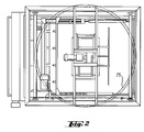
- Figures 1 and 2 show a wrapping machine designed for winding a web of wrapping film 1 from a roll 2 around a stationary object to be packaged.
- the wrapping machine comprises a film dispenser 3.
- the film dispenser 3, carried and guided by a circular guide track 25, moves along a circular path around the object to be wrapped up.
- the film dispenser 3 described in the following can be applied in conjunction with any wrapping machine, such as e.g. one in which the film dispenser 3 is connected to a revolving crank which moves the film dispenser around the object to be wrapped up, or with a wrapping machine in which the film dispenser 3 is connected to a fixed post and the film is passed around an object that is revolved around the dispenser.
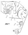
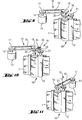
- Figure 3 and also in Figures 5-8 show a film dispenser 3, which comprises a frame 4.
- the frame 4 is provided with supporting elements 26 allowing the film roll to be detachably mounted.
- these supporting elements are located in the openable gate section 7.
- the frame 4 is provided with at least one guide means 5, 11, which is in contact with the first side 1 1 of the film 1, for guiding the film.
- the film dispenser 3 comprises an openable gate section 7, which is provided with at least one guide means 8, 12, which is in contact with the opposite side 1 2 of the film relative to the first side.
- the gate section 7 is pivoted on the frame so that it can be turned between an open position I and a closed position II.
- the film dispenser 3 comprises a pre-stretching device 10 for preliminary stretching of the film.
- the pre-stretching device 10 comprises two pre-stretching rollers, viz. a first pre-stretching roller 11 and a second pre-stretching roller 12.
- the first pre-stretching roller 11 is rotated so that it has a first circumferential velocity v1.
- the second pre-stretching roller 12 is located at a distance from the first pre-stretching roller 11 and it is rotated in the opposite direction relative to the first pre-stretching roller 11.
- the second pre-stretching roller 12 is rotated so that its circumferential velocity v2 differs from the circumferential velocity of the first pre-stretching roller 11.
- the circumferential velocity of the posterior pre-stretching roller is higher than the circumferential velocity of the first pre-stretching roller.
- the pre-stretching of the film takes place as a result of the different circumferential velocities over the film portion between the pre-stretching rollers 11, 12, which are in frictional contact with the film.
- a sufficient contact area between the film and the pre-stretching rollers is achieved by using backup rollers pressing the film against the pre-stretching rollers.
- one of the pre-stretching rollers 11, 12, in this case the first pre-stretching roller 11, is connected to the frame 4 and the other pre-stretching roller 12 is connected to the gate section 7, so that the first pre-stretching roller 11 is in contact with the first side 1 1 of the film and the second pre-stretching roller 12 is in contact with the second side 1 2 .
- the film dispenser 3 comprises a motor 13 with a rotating shaft 14.
- the motor 13 is connected to the fixed frame 4.
- the film dispenser comprises a first set of power transmission elements 15 for transmitting power from the shaft 14 to rotate the first pre-stretching roller 11 and a second set of power transmission elements 16 for transmitting power from the shaft 14 to rotate the second pre-stretching roller 12.
- the first set of power transmission elements 15 comprises a first wheel 17, which is connected to the shaft 14 of the power means 13, a second wheel 18, which is connected to the first pre-stretching roller 11, and an endless driving element 19 fitted to run as an endless loop over the first and second wheels.
- Fig. 9 shows a diagram illustrating the principle of how the power transmission is implemented in the embodiment presented in Fig. 5 and 6.
- the second set of power transmission elements 16 comprises a third wheel 20, which is mounted with a bearing on the frame 3 and so arranged that it can be rotated by the power means 13, and a fourth wheel 21, which is connected to the second pre-stretching roller 12 and adapted to come into power transmitting contact with the third wheel 20 in the closed position II of the gate section 7.
- the third wheel 20 is connected to the first pre-stretching roller 11 on the same axle with the second wheel 18.
- the third wheel 20 and the fourth wheel 21 are toothed gears with tooth systems adapted to each other. The teeth mesh when the gate section 7 is closed. The same thing can be seen from Fig. 3 and 4.
- the detail illustration A in Fig. 4 shows that there are two different third gear wheels 20 mounted successively on the same axle at the end of the first pre-stretching roller 11 to allow a change of transmission ratio.
- a suitable transmission ratio can be selected, thereby changing the speeds of rotation of the pre-stretching rollers.
- the transmission ratio to be selected depends on the thickness and quality of the film and on the desired degree of preliminary strain.
- Fig. 10 presents a diagrammatic illustration of the power transmission application of Fig. 7 and 8.
- the second set of power transmission elements 16 comprises a fifth wheel 22, which is connected to the first pre-stretching roller 11 on the same axle with the second wheel 18, a sixth wheel 23, which is connected to the same axle with the third wheel 20, and an endless driving element 24 fitted to run over the fifth and sixth wheels as an endless loop.
- the third wheel 20 and the fourth wheel 21 are toothed gears with tooth systems adapted to each other. The teeth mesh when the gate section 7 is closed.
- Fig. 11 shows yet another embodiment, in which the second set of power transmission elements 16 for transmitting power to the second pre-stretching roller 12 consists of an endless driving element 19 and a fourth wheel 21 connected to the second pre-stretching roller 12, this fourth wheel 21 being fitted to come into driving engagement with the driving element 19 when the gate section 7 is in its closed position II.
- the endless driving element 19 is an open-link chain, a cogged belt, a trapezoidal belt or the like.
- the second wheel 18, which comes into driving engagement with the driving element 19, is a chain wheel, a cogged wheel, a friction wheel or the like, respectively.
Abstract
Description
Claims (10)
- Wrapping machine for winding a web (1) of wrapping film from a roller (2) around an object to be packaged, said wrapping machine comprising a film dispenser (3) which comprises:a frame (4) provided with at least one guide means (5, 11) which is in contact with the first side (11) of the film 1, for guiding the film;an openable gate section (7) provided with at least one guide means (8, 12) which is in contact with the opposite side (12) of the film relative to the first side, said gate section (7) being pivoted on the frame so that it can be turned between an open position (I) and a closed position (II); anda pre-stretching device (10) for preliminary stretching of the film, said pre-stretching device comprising pre-stretching rollers, viz. a first pre-stretching roller (11), which can be driven at a first circumferential velocity (v1), and a second pre-stretching roller (12), which is disposed at a distance from the first pre-stretching roller and rotated at a circumferential velocity (v2) differing from the first circumferential velocity (v1), so that the preliminary stretching of the film takes place in the film portion between the pre-stretching rollers as a result of the different circumferential velocities, characterized in that one of the pre-stretching roller (11, 12) is connected to the frame (4) and the other one is connected to the gate section (7) in such manner that one of the pre-stretching rollers is in contact with the first side (11) of the film while the other one is in contact with the other side (12).
- Machine as defined in claim 1, characterized in that the film dispenser comprises a power means (13) provided with a rotating shaft (14), said power means being connected to the frame (4); a first set of power transmission elements (15) for transmitting power from the shaft to rotate the first pre-stretching roller (11); and a second set of power transmission elements (16) for transmitting power from the shaft to rotate the second pre-stretching roller (12).
- Machine as defined in claim 2, characterized in that the first set of power transmission elements (15) comprises a first wheel (17) connected to the shaft (14) of the power means (13), a second wheel (18) connected to the first pre-stretching roller (11), and an endless driving element (19) fitted to run over the first and second wheels as an endless loop.
- Machine as defined in claim 2 or 3, characterized in that the second set of power transmission elements (16) comprises a third wheel (20), which is mounted with a bearing on the frame (4) and arranged to be rotated by the power means (13), and a fourth wheel (21), which is connected to the second pre-stretching roller (12) and so fitted that it comes into power transmitting contact with the third wheel (20) in the closed position (II) of the gate section (7).
- Machine as defined in claim 4, characterized in that the third wheel (20) is connected to the first pre-stretching roller (11) on the same axle with the second wheel (18).
- Machine as defined in claim 4, characterized in that the second set of power transmission elements (16) comprises a fifth wheel (22), which is connected to the first pre-stretching roller (11) on the same axle with the second wheel (18), a sixth wheel (23), which is connected to the same shaft with the third wheel (20), and an endless driving element (24) fitted to run as an endless loop over the fifth and sixth wheels.
- Machine as defined in any one of claims 1 - 3, characterized in that the second set of power transmission elements (16) for transmitting power to the second pre-stretching roller (12) consists of an endless driving element (19) and a fourth wheel (21), which is connected to the second pre-stretching roller (12) and fitted to come into driving engagement with the driving element (19) in the closed position (II) of the gate section (7).
- Machine as defined in any one of claims 3 - 5, characterized in that the endless driving element (19 is an open-link chain, a cogged belt, a trapezoidal belt or the like, and that, correspondingly, the second wheel (18) is a chain wheel, a cogged pulley, trapezoidal belt wheel, a toothed gear or the like.
- Machine as defined in any one of claims 1 - 3, characterized in that the third wheel (20) and the fourth wheel (21) are toothed gears with tooth systems adapted to each other.
- Machine as defined in claim 9, characterized in that the transmission ratio of the power transmission elements (15, 16) is so chosen that the circumferential velocity (v2) of the posterior pre-stretching roller as seen in the running direction of the film web is higher than the circumferential velocity (v1) of the anterior pre-stretching roller.
Applications Claiming Priority (2)
| Application Number | Priority Date | Filing Date | Title |
|---|---|---|---|
| FI964819 | 1996-12-02 | ||
| FI964819A FI101282B (en) | 1996-12-02 | 1996-12-02 | Winder |
Publications (2)
| Publication Number | Publication Date |
|---|---|
| EP0845412A1 true EP0845412A1 (en) | 1998-06-03 |
| EP0845412B1 EP0845412B1 (en) | 2000-07-19 |
Family
ID=8547191
Family Applications (1)
| Application Number | Title | Priority Date | Filing Date |
|---|---|---|---|
| EP97660111A Expired - Lifetime EP0845412B1 (en) | 1996-12-02 | 1997-10-17 | Wrapping machine |
Country Status (8)
| Country | Link |
|---|---|
| US (1) | US5875616A (en) |
| EP (1) | EP0845412B1 (en) |
| AU (1) | AU689416B1 (en) |
| BR (1) | BR9705385A (en) |
| CA (1) | CA2220719C (en) |
| DE (1) | DE69702583T2 (en) |
| ES (1) | ES2150206T3 (en) |
| FI (1) | FI101282B (en) |
Cited By (3)
| Publication number | Priority date | Publication date | Assignee | Title |
|---|---|---|---|---|
| WO2002030750A1 (en) * | 2000-10-07 | 2002-04-18 | Thomas Schuster | Strapping device |
| EP2060493A1 (en) * | 2007-11-13 | 2009-05-20 | Oy M. Haloila Ab | Film delivery device and use of same |
| IT202100011720A1 (en) * | 2021-05-07 | 2022-11-07 | A C M I Spa | MACHINE FOR STABILIZING PALLETIZED LOADS WITH REEL CHANGE SYSTEM |
Families Citing this family (18)
| Publication number | Priority date | Publication date | Assignee | Title |
|---|---|---|---|---|
| US6082081A (en) * | 1998-07-10 | 2000-07-04 | Mucha; Jacek | Powered prestretched film delivery apparatus |
| IT1309676B1 (en) * | 1999-03-26 | 2002-01-30 | Robopac Sa | DEVICE FOR LOADING FILMS ON MACHINES FOR WRAPPING PRODUCTS |
| FI109113B (en) * | 2000-02-17 | 2002-05-31 | Haloila M Oy Ab | Wrapping |
| JP3622078B2 (en) * | 2000-04-04 | 2005-02-23 | 松本システムエンジニアリング株式会社 | Package packaging method and apparatus |
| US20040065314A1 (en) * | 2000-07-20 | 2004-04-08 | Layer James H. | Apparatus, systems, and methods for warming materials |
| ITBO20010259A1 (en) * | 2001-04-27 | 2002-10-27 | Aetna Group Spa | EQUIPMENT FOR WRAPPING PRODUCTS WITH PLASTIC FILM |
| FI116669B (en) | 2003-09-05 | 2006-01-31 | Haloila M Oy Ab | wrapping machine |
| US20060254213A1 (en) * | 2005-04-20 | 2006-11-16 | Samuel Strapping Systems, Inc. | System and method for pre-stretching plastic material |
| ITMO20060221A1 (en) | 2006-07-07 | 2008-01-08 | Aetna Group Spa | WRAPPING MACHINE AND WINDING METHODS |
| CA2640944A1 (en) * | 2007-10-12 | 2009-04-12 | Cousins Packaging Inc. | Carriage for a stretch wrapping machine |
| FI20085071A0 (en) * | 2008-01-30 | 2008-01-30 | Haloila M Oy Ab | Equipment, procedure and film for film wrapping |
| US20090235617A1 (en) * | 2008-03-24 | 2009-09-24 | Moore Philip R | Wrapping apparatus having top loading and threading film dispenser |
| JP4633834B2 (en) * | 2008-10-22 | 2011-02-16 | トヨタ自動車株式会社 | Film stretcher |
| AU2010260150A1 (en) * | 2009-06-15 | 2012-01-19 | Lantech. Com, Llc | Wrapping apparatus having top loading and threading dispenser |
| US20110067364A1 (en) * | 2009-09-22 | 2011-03-24 | Cousins Neil G | Carriage For A Stretch Wrapping Machine |
| US11066198B2 (en) * | 2012-06-18 | 2021-07-20 | TAB Industries, LLC | Stretch film dispenser for orbital pallet wrappers |
| JP6594836B2 (en) * | 2016-09-29 | 2019-10-23 | 株式会社フジキカイ | Film supply device in horizontal bag making and filling machine |
| US11352152B2 (en) * | 2019-09-20 | 2022-06-07 | Signode Industrial Group Llc | Stretch-wrapping machine with self-adjusting pinch rollers |
Citations (4)
| Publication number | Priority date | Publication date | Assignee | Title |
|---|---|---|---|---|
| EP0243861A1 (en) * | 1986-05-02 | 1987-11-04 | Cyklop International Ag | Machine for spirally enveloping packaging goods with a web of plastic stretch foil |
| EP0293352A2 (en) * | 1987-05-27 | 1988-11-30 | Newtec International | Device and method for exchanging a film roll in wrapping |
| EP0467729A1 (en) * | 1990-07-16 | 1992-01-22 | Newtec International | Method and machine for packaging the lateral face and an end face of a charge |
| US5447009A (en) * | 1993-09-22 | 1995-09-05 | Newtec International (Societe Anonyme) | Method and apparatus of banded wrapping of a palletized load |
Family Cites Families (8)
| Publication number | Priority date | Publication date | Assignee | Title |
|---|---|---|---|---|
| US4418510A (en) * | 1979-09-12 | 1983-12-06 | Lantech, Inc. | Stretch wrapping apparatus and process |
| US4387548A (en) * | 1979-11-21 | 1983-06-14 | Lantech, Inc. | Power assisted roller-stretch wrapping process |
| US4302920A (en) * | 1979-11-21 | 1981-12-01 | Lantech Inc. | Film web drive stretch wrapping apparatus and process |
| GB2107668B (en) * | 1981-10-13 | 1985-08-21 | Inpac Automation Limited | Stretch wrapping apparatus |
| JPS6322317A (en) * | 1986-05-23 | 1988-01-29 | ミマ・インコ−ポレ−テッド | Multistage spare extension packer and packaging method usingsaid packer |
| US4747254A (en) * | 1987-01-02 | 1988-05-31 | Lantech, Inc. | Web threading device |
| US5414979A (en) * | 1993-04-23 | 1995-05-16 | Lantech, Inc. | Stretch wrapping apparatus |
| FR2742416B1 (en) * | 1995-12-13 | 1998-02-06 | Thimon | PRE-STRETCHED FILM, DEVICE AND METHOD FOR OVERPACKING |
-
1996
- 1996-12-02 FI FI964819A patent/FI101282B/en not_active IP Right Cessation
-
1997
- 1997-10-17 EP EP97660111A patent/EP0845412B1/en not_active Expired - Lifetime
- 1997-10-17 ES ES97660111T patent/ES2150206T3/en not_active Expired - Lifetime
- 1997-10-17 DE DE69702583T patent/DE69702583T2/en not_active Expired - Lifetime
- 1997-10-22 US US08/956,152 patent/US5875616A/en not_active Expired - Lifetime
- 1997-11-10 CA CA002220719A patent/CA2220719C/en not_active Expired - Fee Related
- 1997-11-17 BR BR9705385A patent/BR9705385A/en not_active IP Right Cessation
- 1997-11-25 AU AU45360/97A patent/AU689416B1/en not_active Ceased
Patent Citations (4)
| Publication number | Priority date | Publication date | Assignee | Title |
|---|---|---|---|---|
| EP0243861A1 (en) * | 1986-05-02 | 1987-11-04 | Cyklop International Ag | Machine for spirally enveloping packaging goods with a web of plastic stretch foil |
| EP0293352A2 (en) * | 1987-05-27 | 1988-11-30 | Newtec International | Device and method for exchanging a film roll in wrapping |
| EP0467729A1 (en) * | 1990-07-16 | 1992-01-22 | Newtec International | Method and machine for packaging the lateral face and an end face of a charge |
| US5447009A (en) * | 1993-09-22 | 1995-09-05 | Newtec International (Societe Anonyme) | Method and apparatus of banded wrapping of a palletized load |
Cited By (4)
| Publication number | Priority date | Publication date | Assignee | Title |
|---|---|---|---|---|
| WO2002030750A1 (en) * | 2000-10-07 | 2002-04-18 | Thomas Schuster | Strapping device |
| EP2060493A1 (en) * | 2007-11-13 | 2009-05-20 | Oy M. Haloila Ab | Film delivery device and use of same |
| IT202100011720A1 (en) * | 2021-05-07 | 2022-11-07 | A C M I Spa | MACHINE FOR STABILIZING PALLETIZED LOADS WITH REEL CHANGE SYSTEM |
| EP4086182A1 (en) * | 2021-05-07 | 2022-11-09 | A.C.M.I. - Societa' Per Azioni | Machine for stabilising palletised loads with reel change system |
Also Published As
| Publication number | Publication date |
|---|---|
| CA2220719C (en) | 2002-05-07 |
| DE69702583D1 (en) | 2000-08-24 |
| EP0845412B1 (en) | 2000-07-19 |
| FI964819A0 (en) | 1996-12-02 |
| DE69702583T2 (en) | 2001-04-19 |
| BR9705385A (en) | 1999-03-23 |
| ES2150206T3 (en) | 2000-11-16 |
| AU689416B1 (en) | 1998-03-26 |
| FI101282B1 (en) | 1998-05-29 |
| US5875616A (en) | 1999-03-02 |
| CA2220719A1 (en) | 1998-06-02 |
| FI101282B (en) | 1998-05-29 |
Similar Documents
| Publication | Publication Date | Title |
|---|---|---|
| EP0845412A1 (en) | Wrapping machine | |
| US6446418B1 (en) | Packaging device | |
| US4693053A (en) | Device for controlling the unwinding of a plastics film in a packaging machine | |
| US7661244B2 (en) | Packaging apparatus for helically wrapping articles | |
| EP1125841B1 (en) | Apparatus for winding a wrapping film about an article | |
| US4691499A (en) | Method of tensioning a web of packaging material | |
| FI82011B (en) | FOERFARANDE OCH ANORDNING FOER SVEPNING AV PLASTFOLIE RUNT EN VARA. | |
| US4328742A (en) | Strapping apparatus feed and tension mechanism | |
| US5313689A (en) | Sliver drawing rollers driven by belts including belt cleaners | |
| NZ212620A (en) | Dough rolling device; reciprocating conveyors beneath a roller mechanism | |
| EP1524192B1 (en) | Wrapping machine | |
| DE2319378C3 (en) | Machine for the automatic strapping of packages with plastic tape | |
| KR100189214B1 (en) | Infeed station for converting a continuously moving web-like sheet into an intermittently fed web-like sheet for a subsequent processing station | |
| NL8100406A (en) | DEVICE FOR MANUFACTURING A CORRUGATED TUBE COMPENSATOR FROM A CIRCULAR CYLINDRICAL TUBE OF SHEET METAL. | |
| CA2052183A1 (en) | Biaxial Stretch Wrapping | |
| EP0685417B1 (en) | Method for the mutual repositioning of products, for instance for adjusting the mutual position of graphic products in a packing apparatus, and a feeding apparatus for applying that method | |
| US5611194A (en) | Tuck roller with improved web tension control | |
| US4461554A (en) | Self-reeling cassette driven by the motion of an inserted web | |
| JP3240147B2 (en) | Belt drive differential | |
| MX9800836A (en) | Belt pretensioner for a safety belt. | |
| US4236278A (en) | Planetary coiler especially useful for coiling textile strand material | |
| US3738556A (en) | Apparatus for guiding a foil web | |
| JPS6121458Y2 (en) | ||
| JPS6026840A (en) | Driving jocky pulley | |
| AU722548B2 (en) | A packaging device |
Legal Events
| Date | Code | Title | Description |
|---|---|---|---|
| PUAI | Public reference made under article 153(3) epc to a published international application that has entered the european phase |
Free format text: ORIGINAL CODE: 0009012 |
|
| AK | Designated contracting states |
Kind code of ref document: A1 Designated state(s): CH DE ES FR GB IT LI NL PT |
|
| 17P | Request for examination filed |
Effective date: 19980518 |
|
| 17Q | First examination report despatched |
Effective date: 19981006 |
|
| AKX | Designation fees paid |
Free format text: CH DE ES FR GB IT LI NL PT |
|
| RBV | Designated contracting states (corrected) |
Designated state(s): CH DE ES FR GB IT LI NL PT |
|
| GRAG | Despatch of communication of intention to grant |
Free format text: ORIGINAL CODE: EPIDOS AGRA |
|
| GRAG | Despatch of communication of intention to grant |
Free format text: ORIGINAL CODE: EPIDOS AGRA |
|
| GRAH | Despatch of communication of intention to grant a patent |
Free format text: ORIGINAL CODE: EPIDOS IGRA |
|
| GRAH | Despatch of communication of intention to grant a patent |
Free format text: ORIGINAL CODE: EPIDOS IGRA |
|
| GRAA | (expected) grant |
Free format text: ORIGINAL CODE: 0009210 |
|
| AK | Designated contracting states |
Kind code of ref document: B1 Designated state(s): CH DE ES FR GB IT LI NL PT |
|
| REG | Reference to a national code |
Ref country code: CH Ref legal event code: EP |
|
| REF | Corresponds to: |
Ref document number: 69702583 Country of ref document: DE Date of ref document: 20000824 |
|
| ITF | It: translation for a ep patent filed |
Owner name: STUDIO TORTA S.R.L. |
|
| PG25 | Lapsed in a contracting state [announced via postgrant information from national office to epo] |
Ref country code: PT Free format text: LAPSE BECAUSE OF FAILURE TO SUBMIT A TRANSLATION OF THE DESCRIPTION OR TO PAY THE FEE WITHIN THE PRESCRIBED TIME-LIMIT Effective date: 20001019 |
|
| ET | Fr: translation filed | ||
| REG | Reference to a national code |
Ref country code: CH Ref legal event code: NV Representative=s name: E. BLUM & CO. PATENTANWAELTE |
|
| REG | Reference to a national code |
Ref country code: ES Ref legal event code: FG2A Ref document number: 2150206 Country of ref document: ES Kind code of ref document: T3 |
|
| PLBE | No opposition filed within time limit |
Free format text: ORIGINAL CODE: 0009261 |
|
| STAA | Information on the status of an ep patent application or granted ep patent |
Free format text: STATUS: NO OPPOSITION FILED WITHIN TIME LIMIT |
|
| 26N | No opposition filed | ||
| REG | Reference to a national code |
Ref country code: GB Ref legal event code: IF02 |
|
| REG | Reference to a national code |
Ref country code: CH Ref legal event code: PFA Owner name: OY M. HALOILA AB Free format text: OY M. HALOILA AB#RUSKONTIE 16#21250 MASKU (FI) -TRANSFER TO- OY M. HALOILA AB#RUSKONTIE 16#21250 MASKU (FI) |
|
| PGFP | Annual fee paid to national office [announced via postgrant information from national office to epo] |
Ref country code: CH Payment date: 20091026 Year of fee payment: 13 |
|
| PGFP | Annual fee paid to national office [announced via postgrant information from national office to epo] |
Ref country code: NL Payment date: 20091024 Year of fee payment: 13 |
|
| REG | Reference to a national code |
Ref country code: NL Ref legal event code: V1 Effective date: 20110501 |
|
| REG | Reference to a national code |
Ref country code: CH Ref legal event code: PL |
|
| PG25 | Lapsed in a contracting state [announced via postgrant information from national office to epo] |
Ref country code: LI Free format text: LAPSE BECAUSE OF NON-PAYMENT OF DUE FEES Effective date: 20101031 Ref country code: CH Free format text: LAPSE BECAUSE OF NON-PAYMENT OF DUE FEES Effective date: 20101031 |
|
| PG25 | Lapsed in a contracting state [announced via postgrant information from national office to epo] |
Ref country code: NL Free format text: LAPSE BECAUSE OF NON-PAYMENT OF DUE FEES Effective date: 20110501 |
|
| REG | Reference to a national code |
Ref country code: FR Ref legal event code: PLFP Year of fee payment: 19 |
|
| REG | Reference to a national code |
Ref country code: FR Ref legal event code: PLFP Year of fee payment: 20 |
|
| PGFP | Annual fee paid to national office [announced via postgrant information from national office to epo] |
Ref country code: DE Payment date: 20161027 Year of fee payment: 20 Ref country code: FR Payment date: 20161025 Year of fee payment: 20 Ref country code: GB Payment date: 20161027 Year of fee payment: 20 |
|
| PGFP | Annual fee paid to national office [announced via postgrant information from national office to epo] |
Ref country code: ES Payment date: 20161026 Year of fee payment: 20 Ref country code: IT Payment date: 20161024 Year of fee payment: 20 |
|
| REG | Reference to a national code |
Ref country code: DE Ref legal event code: R071 Ref document number: 69702583 Country of ref document: DE |
|
| REG | Reference to a national code |
Ref country code: GB Ref legal event code: PE20 Expiry date: 20171016 |
|
| PG25 | Lapsed in a contracting state [announced via postgrant information from national office to epo] |
Ref country code: GB Free format text: LAPSE BECAUSE OF EXPIRATION OF PROTECTION Effective date: 20171016 |
|
| REG | Reference to a national code |
Ref country code: ES Ref legal event code: FD2A Effective date: 20180508 |
|
| PG25 | Lapsed in a contracting state [announced via postgrant information from national office to epo] |
Ref country code: ES Free format text: LAPSE BECAUSE OF EXPIRATION OF PROTECTION Effective date: 20171018 |