EP0845285B1 - Destillation apparatus - Google Patents
Destillation apparatus Download PDFInfo
- Publication number
- EP0845285B1 EP0845285B1 EP97119293A EP97119293A EP0845285B1 EP 0845285 B1 EP0845285 B1 EP 0845285B1 EP 97119293 A EP97119293 A EP 97119293A EP 97119293 A EP97119293 A EP 97119293A EP 0845285 B1 EP0845285 B1 EP 0845285B1
- Authority
- EP
- European Patent Office
- Prior art keywords
- cartridge
- catalyst
- catalyser
- cartridges
- distillation apparatus
- Prior art date
- Legal status (The legal status is an assumption and is not a legal conclusion. Google has not performed a legal analysis and makes no representation as to the accuracy of the status listed.)
- Expired - Lifetime
Links
Images
Classifications
-
- B—PERFORMING OPERATIONS; TRANSPORTING
- B01—PHYSICAL OR CHEMICAL PROCESSES OR APPARATUS IN GENERAL
- B01D—SEPARATION
- B01D3/00—Distillation or related exchange processes in which liquids are contacted with gaseous media, e.g. stripping
- B01D3/34—Distillation or related exchange processes in which liquids are contacted with gaseous media, e.g. stripping with one or more auxiliary substances
-
- B—PERFORMING OPERATIONS; TRANSPORTING
- B01—PHYSICAL OR CHEMICAL PROCESSES OR APPARATUS IN GENERAL
- B01D—SEPARATION
- B01D3/00—Distillation or related exchange processes in which liquids are contacted with gaseous media, e.g. stripping
- B01D3/009—Distillation or related exchange processes in which liquids are contacted with gaseous media, e.g. stripping in combination with chemical reactions
-
- C—CHEMISTRY; METALLURGY
- C12—BIOCHEMISTRY; BEER; SPIRITS; WINE; VINEGAR; MICROBIOLOGY; ENZYMOLOGY; MUTATION OR GENETIC ENGINEERING
- C12H—PASTEURISATION, STERILISATION, PRESERVATION, PURIFICATION, CLARIFICATION OR AGEING OF ALCOHOLIC BEVERAGES; METHODS FOR ALTERING THE ALCOHOL CONTENT OF FERMENTED SOLUTIONS OR ALCOHOLIC BEVERAGES
- C12H6/00—Methods for increasing the alcohol content of fermented solutions or alcoholic beverages
- C12H6/02—Methods for increasing the alcohol content of fermented solutions or alcoholic beverages by distillation
Definitions
- the present invention relates to a distillation device for the production of fires, with a mash container, one Reinforcement column or a hat, a cooler and one Catalyst with a housing between the reinforcement column or the hat and the cooler is arranged and one Has bed or a pack of catalyst parts.
- the one used in the known distillation apparatus Catalyst is with a loose bed of copper molded parts filled.
- an outlet opening is provided on the catalyst.
- This outlet can be through a pipeline or a piping system directly with the mash bladder and / or with the reinforcement column be connected so that the nut can be "recycled”.
- This distillation device prevents the Lutter in the cooler can be a low-pollutant distillate be won.
- the catalyst parts in a cartridge to arrange and design the housing of the catalyst so that the cartridge can be removed and replaced is not necessary the need to clean the catalytic converter from to disconnect the connected pipes. If a cleaning the catalyst parts is necessary, the cartridge from the Housing removed, without the inlet or outlet connection of the catalyst from the corresponding pipes. After cleaning, the cartridge can be used again in the same way be used.
- the catalyst parts can be in bulk or as fixed elements (or in the form of lamellas or Finned tubes) are provided so that the catalyst parts either in bulk or in packs.
- the measure according to the invention also has the Advantage that while cleaning a catalyst cartridge a replacement cartridge can be inserted into the catalyst housing can, so that the distillation device has longer runtimes may have.
- Another advantage is that the cartridge is simple can be removed if a distillation process without Catalyst effect is desired. So it’s not necessary in the distillation device according to the invention one to the Catalyst parallel line and a corresponding switch valve provided.
- the cartridge and the housing are preferably in this way to one another adapted that in the catalyst resulting Lutter via a Opening in the housing can drain.
- the catalyst at least has two interchangeable cartridges and if that Housing is designed so that flowing through the catalyst Spirit vapors passed through the individual cartridges one after the other become.
- the housing has at least one Deflection channel that serially connects the individual cartridges combines.
- the deflection channel is in one Cover is designed to replace the individual cartridges is removable from the housing.
- the Spirit vapors escaping from the last single cartridge past the individual cartridges to an outlet port of the Catalyst passed.
- the cartridge can the spirit or water vapors are heated.
- the housing can also be designed in this way be that both alternatives are possible either by switching are.
- the catalyst has at least two individual cartridges and one Valve arrangement on between the individual cartridges and one Inlet port and an outlet port of the catalyst is connected and a switch between parallel and serial operation of the individual cartridges.
- the individual cartridges are preferably elongated and are aligned parallel to each other in the housing.
- the cartridge has at least is provided with two channels, with different catalyst parts can be equipped.
- the cartridge can be used with different Catalyst materials are loaded.
- this kind of cartridge also possible, more or less material of the same catalyst type to provide the duration of contact with to lengthen or shorten the spirit vapors.
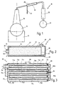
- Fig. 1 is a distillation device according to the invention generally designated by the reference number 10.
- the distillation device 10 has a mash container 12, which can be heated by a heating device 14. The by heating the mash in the mash container 12 rising spirit vapors are in the reinforcement column 16 concentrated in a known manner. The concentrated ones Spirit vapors become a catalyst from the boost column 16 18 fed via a pipeline. The the catalyst 18 spirit vapors are left over another pipe a cooler 20, in which the concentrated and catalyzed spirit vapors are condensed. The finished Distillate is collected in a spirit collector 22.
- the catalyst 18 is connected to a lutter return line 24 provided to return the resulting in the catalyst 18 Lutter place on the mash bladder and / or the reinforcement column 16 to be able to. In this way the Lutter can be "recycled".
- a cartridge 26 can be inserted into the catalyst 18 without the pipes leading to and from the catalytic converter to have to solve. When the cartridge is not inserted 26 go from the concentration column 16 concentrated Spirit vapors thus directly into the cooler 20.
- the distillation device 10 is suitable for production of all kinds of fires, in particular for the production of fruit brandies.
- the Catalyst 18 particularly useful because of the Lutter recycling a pollutant-free, so no urethane carbamate or distillate containing cyanides can be obtained.
- Fig. 2 another embodiment is one of the Distillation device 10 catalyst to be used in general designated with the reference number 30.
- the catalytic converter 30 has an approximately tubular housing 32, by a piece of pipe 34 closed at a first end and one that can be placed on the other end of the tube piece 34 and is formed from this easily removable cover 36.
- an inlet connection 38 intended for spirit vapors.
- An outlet nozzle 40 for Spirit vapors is on the pipe section 34 on the jacket side in the area of the second end.
- a tubular cartridge is also in the tube piece 34 42 introduced, the outer diameter about the inner diameter corresponds to the pipe section 34.
- the cartridge 42 essentially consists of a tube piece, which is filled with catalyst material 44 and the ends thereof are formed by sieves 46.
- the sieves 46 are designed that the catalyst material 44 inside the cartridge 42nd is kept by spirit vapors and any Lutter however, they can pass through.
- a pin 48 is provided on the inside of the cover 36, by means of which the cartridge 42 on the inner wall of the first End of the pipe section 34 is pressed to ensure that spirit vapors entering through the inlet connection 38 do not are passed past the cartridge 42.
- Lutter opening 50 is provided, which is designed and arranged is that in the cartridge 42 accumulating Lutter on the adjacent sieve 46 from the housing 32 of the catalyst 30 can drain off.
- cartridge 42 When cartridge 42 is inserted, they pass through the inlet connection 38 entering spirit vapors first through the neighboring Sieve 46, then flow through the catalyst material filling 44 of the cartridge 42 and pass over the second sieve 46 and out of the catalytic converter 30 via the outlet connection 50, from where they are directed to the cooler 20.
- the Lutter can drain through the opening 50.
- the cartridge 42 by removing the Lid 36 easily removed from the pipe section 34 and again can be used without pipes from the nozzle 38, 40 or the opening 50 to have to solve. Beyond that it is also possible a distillation process without inserted Perform cartridge 42. In this case the housing works 32 as a pure pipe. In addition, it is also possible Cartridges with different catalyst materials 44 use.
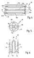
- 3 is a third embodiment of a catalyst generally designated by the reference number 60.
- the catalytic converter 60 has a housing 62 which is connected to a Inlet port 64 and an outlet port 66 for spirit vapors and is provided with a nut opening 68.
- the housing 62 has a front side 70 and a rear side 72, with the inlet port 64 on the front is provided and wherein the outlet port 66 between the Front 70 and the back 72 in a lateral surface of the Housing 62 is arranged.
- cartridge slots 74a-d are provided in the housing 62, which are arranged parallel to each other.
- the first cartridge shaft 74a extends from the inlet connection 64 to the Rear 72 of the housing 62.
- the cartridge slots 74b and 74c each extend from the front 70 to the rear 72.
- the cartridge slot 74d extends from the rear 72 to just before the front 70.
- cartridges 76a-d are in the cartridge slots 74a-d used, whose dimensions are identical, but with different catalyst materials can be filled.
- a deflection channel 78 is provided on the front side 70 through the two cartridge slots 74b and 74c are connected.
- a cover 80 is provided on the rear side 72.
- Lids 80 can remove the cartridges 76a-d from the cartridge slots 74a-d can be removed.
- the lid 80 is with provided two further deflection channels 82a and 82b, the Deflection channel 82a connects the cartridges 76a and 76b and wherein the deflection channel 82b connects the cartridges 76c and 76d.
- On the lid 80 is also a handle 84 is provided around the Lid 80 easier to handle.
- the four cartridges are through the deflection channels 78, 82a, 82b 76a-d connected in series. Over the inlet nozzle 74 entering spirit vapors are through the first cartridge 76a to the deflection channel 82a, from there into the cartridge 76b, from which the spirit vapors are led to the deflection channel 78. The spirit vapors enter from the deflection channel 78 Cartridge 76c and are then via the deflection channel 82b passed into the cartridge 76d.
- the 4 is a fourth embodiment of a catalyst generally designated by the reference number 90.
- the representation 4 is of a purely schematic nature. Constructional details of the catalysts 30 and 60 shown in FIGS. 2 and 3 can also be applied to this embodiment.
- the catalytic converter 90 has a housing 92 with an inlet connection 94 and an outlet 96 for spirit vapors. A nut opening 98 is also provided.
- the housing 92 there are three catalyst cartridges in the housing 92 100a, 100b and 100c arranged parallel to each other.
- the inlet and outlet openings of the cartridges 100a-c are each equipped with valves 102a, 102b, 102c and 104a, 104b and 104c connected.
- the valves 102a-c are each with connected to the inlet port 94 and continue to the valves 102a and 102b and the valves 102b and 102c with each other connected.
- valves 104a-c are each with the outlet port 96 connected. Furthermore, the valves 104a and 104b and the Valves 104b and 104c interconnected.
- valves 102, 104 are in the housing in this embodiment 92 arranged. However, it is understood that the valves too can be arranged outside the housing.
- the illustrated The arrangement of the valves 102, 104 is highly variable designed and can be simplified as long as one Switching from serial to parallel operation is possible.
- the valves 102, 104 enable the three cartridges 100a-c interconnect in any way. So can the cartridges are connected in series or in parallel operated to each other. It is also possible to use only one or two of the cartridges - either serial or parallel to each other - to operate and one or two cartridges 100 to idle to let.
- the catalyst 90 is therefore particularly suitable for Applications where empirically ideal in a simple way Taste and smell notes are to be found out.
- FIG. 5 shows in a schematic form a preferred possibility the individual cartridges 76a-d of the catalyst shown in FIG. 3 60 to be arranged in a tubular housing.
- the arrangement is essentially star-shaped, so that for the four individual cartridges 76 of the catalyst 60, a housing 62 with a minimum tube diameter can be provided.
- a housing 62 with a minimum tube diameter can be provided.
- FIG. 6 shows an alternative in a schematic development Embodiment of a cartridge 110.
- the cartridge 110 is with four channels 112 provided, each in the same or different Catalyst materials can be used.
- the four Channels 112 are in series with each other through connection channels 116 connected so that the spirit vapors into one of the channels 112 enter and exit from another of channels 112.
- the Channels 112 are also each with a blind cap 114 to insert catalyst material into the channels 112 or to be able to take from these. It is understood that the Cartridge 110 preferably with catalyst material inserts in the form of fins or finned tubes to be fitted prevent loose catalyst materials over the Mix connecting channels 116 together.
- a distillation device the one with a catalyst housing to hold a single Cartridge is provided with different catalyst materials or with different catalyst material contact times operate.
- the catalysts 18, 30, 60, 90 can be arranged in any installation position.
- the nut openings 24, 50, 68, 98 are each to be provided that the nut flow out of the catalyst housing as well as possible can.
Landscapes
- Chemical & Material Sciences (AREA)
- Chemical Kinetics & Catalysis (AREA)
- Organic Chemistry (AREA)
- Engineering & Computer Science (AREA)
- General Health & Medical Sciences (AREA)
- Biochemistry (AREA)
- Bioinformatics & Cheminformatics (AREA)
- General Engineering & Computer Science (AREA)
- Life Sciences & Earth Sciences (AREA)
- Genetics & Genomics (AREA)
- Health & Medical Sciences (AREA)
- Wood Science & Technology (AREA)
- Zoology (AREA)
- Food Science & Technology (AREA)
- Vaporization, Distillation, Condensation, Sublimation, And Cold Traps (AREA)
- Organic Low-Molecular-Weight Compounds And Preparation Thereof (AREA)
Abstract
Description
Die vorliegende Erfindung betrifft eine Destillationsvorrichtung zur Herstellung von Bränden, mit einem Maischebehälter, einer Verstärkungskolonne oder einem Hut, einem Kühler und einem Katalysator mit einem Gehäuse, der zwischen der Verstärkungskolonne oder dem Hut und dem Kühler angeordnet ist und der eine Schüttung oder eine Packung von Katalysatorteilen aufweist.The present invention relates to a distillation device for the production of fires, with a mash container, one Reinforcement column or a hat, a cooler and one Catalyst with a housing between the reinforcement column or the hat and the cooler is arranged and one Has bed or a pack of catalyst parts.
Eine solche Destillationsvorrichtung ist aus der EP 0 355 773 A2 bekannt.Such a distillation device is known from EP 0 355 773 A2 known.
Der bei der bekannten Destillationsvorrichtung verwendete Katalysator ist mit einer losen Schüttung aus kupfernen Formteilen gefüllt. Für den im Katalysator ausfallenden Lutter ist an dem Katalysator eine Auslaßöffnung vorgesehen. Diese Auslaßöffnung kann durch eine Rohrleitung oder ein Rohrleitungssystem direkt mit der Maischeblase und/oder mit der Verstärkungskolonne verbunden sein, so daß der Lutter "recycelt" werden kann. Da mit dieser Destillationsvorrichtung verhindert wird, daß der Lutter in den Kühler gelangt, kann ein schadstoffarmes Destillat gewonnen werden. Insbesondere können sich kein Urethancarbamat bzw. Ethylcarbonat in dem fertigen Destillat aufgrund von Lichteinfluß bilden, da das Destillat keine Cyanide enthält.The one used in the known distillation apparatus Catalyst is with a loose bed of copper molded parts filled. For the precipitating in the catalyst an outlet opening is provided on the catalyst. This outlet can be through a pipeline or a piping system directly with the mash bladder and / or with the reinforcement column be connected so that the nut can be "recycled". There this distillation device prevents the Lutter in the cooler can be a low-pollutant distillate be won. In particular, no urethane carbamate or ethyl carbonate in the finished distillate due to Form the influence of light because the distillate contains no cyanides.
Es hat sich jedoch gezeigt, daß der Aufwand zur Reinigung des Katalysators relativ aufwendig ist. Denn hierzu müssen ein Geistdämpfeeintrittsstutzen, ein Geistdämpfeaustrittsstutzen und die Lutterrückführleitung von dem Katalysator gelöst werden. However, it has been shown that the effort for cleaning the Catalyst is relatively expensive. Because this requires a Spirit vapor inlet nozzle, a spirit vapor outlet nozzle and the mother return line are detached from the catalyst.
Zudem ist es so, daß es nicht bei allen Destillationen erwünscht ist, die Geistdämpfe durch einen Kupferkatalysator strömen zu lassen.In addition, it is not desirable for all distillations is, the spirit vapors flow through a copper catalyst to let.
Ähnliche Probleme ergeben sich bei einer Destillationsvorrichtung, die aus der JP 59-166077A bzw. JAPAN-Abstract C-262, Vol. 9, Nr. 17, 24. Januar 1985 bekannt geworden ist. Aus dieser Druckschrift ist es nämlich auch bekannt, einen Katalysator mit einer Schüttung aus Katalysatorteilchen fest in einer Rohrleitung zwischen Verstärkungskolonne und Kühler zu verankern. Zum Reinigen des Katalysators müssen auch hier die Rohrleitungen abgeschraubt werden.Similar problems arise with a distillation device, from JP 59-166077A or JAPAN abstract C-262, Vol. 9, No. 17, January 24, 1985. From this Document is namely known, a catalyst with a bed of catalyst particles solid in one Anchoring the pipeline between the reinforcement column and the cooler. To clean the catalytic converter, the pipelines must also be used here be unscrewed.
Aus der eingangs genannten EP 0 355 773 A2 ist es ferner bekannt, parallel zu dem Katalysator eine Umgehungsleitung und ein umschaltbares Ventil vorzusehen, so daß der Anwender bei jedem Destillationsvorgang frei wählen kann, ob die Geistdämpfe den Kupferkatalysator durchströmen sollen oder nicht. Hierdurch wird natürlich auch der Reinigungsaufwand verringert, da der Katalysator nicht so häufig gereinigt werden muß. Nichtsdestotrotz muß auch dieser Katalysator vor einer Reinigung an seinen Stutzen von den entsprechenden Rohrleitungen gelöst werden.From EP 0 355 773 A2 mentioned at the outset it is also known a bypass line and a parallel to the catalyst switchable valve to provide, so that the user at each Distillation process can choose whether the spirit vapors Should flow through copper catalyst or not. hereby the cleaning effort is of course also reduced, since the Catalyst does not need to be cleaned as often. Nevertheless this catalyst must also be on before cleaning its nozzle detached from the corresponding pipes become.
Es ist demgemäß die Aufgabe der vorliegenden Erfindung, eine Destillationsvorrichtung anzugeben, deren Katalysator leichter zu reinigen ist. It is accordingly the object of the present invention, a Specify distillation device whose catalyst is lighter is to be cleaned.
Diese Aufgabe wird bei der eingangs genannten Destillationsvorrichtung dadurch gelöst, daß die Katalysatorteile in wenigstens einer Kartusche aufgenommen sind und daß das Gehäuse des Katalysators so ausgebildet ist, daß die Kartusche entnehmbar und austauschbar ist.This object is achieved in the distillation device mentioned at the beginning solved in that the catalyst parts in at least a cartridge are included and that the housing of the Catalyst is designed so that the cartridge can be removed and is interchangeable.
Die Aufgabe wird somit vollkommen gelöst.The task is thus solved completely.
Denn durch die Maßnahme, die Katalysatorteile in einer Kartusche anzuordnen und das Gehäuse des Katalysators so zu gestalten, daß die Kartusche entnehmbar und austauschbar ist, entfällt die Notwendigkeit, den Katalysator zu Reinigungszwecken von den angeschlossenen Rohrleitungen zu lösen. Falls eine Reinigung der Katalysatorteile notwendig ist, wird die Kartusche aus dem Gehäuse entnommen, ohne die Eintritts- bzw. Austrittsstutzen des Katalysators von den entsprechenden Rohrleitungen zu trennen. Nach dem Reinigen kann die Kartusche auf dieselbe Weise wieder eingesetzt werden. Die Katalysatorteile können als Schüttgut oder als feststehende Elemente (bzw. in Form von Lamellen oder Lamellenrohren) vorgesehen sein, so daß die Katalysatorteile entweder als Schüttung oder als Packung vorliegen.Because by the measure, the catalyst parts in a cartridge to arrange and design the housing of the catalyst so that the cartridge can be removed and replaced is not necessary the need to clean the catalytic converter from to disconnect the connected pipes. If a cleaning the catalyst parts is necessary, the cartridge from the Housing removed, without the inlet or outlet connection of the catalyst from the corresponding pipes. After cleaning, the cartridge can be used again in the same way be used. The catalyst parts can be in bulk or as fixed elements (or in the form of lamellas or Finned tubes) are provided so that the catalyst parts either in bulk or in packs.
Die erfindungsgemäße Maßnahme hat darüber hinaus auch den Vorteil, daß während der Reinigung einer Katalysatorkartusche eine Ersatzkartusche in das Katalysatorgehäuse eingesetzt werden kann, so daß die Destillationsvorrichtung längere Laufzeiten haben kann.The measure according to the invention also has the Advantage that while cleaning a catalyst cartridge a replacement cartridge can be inserted into the catalyst housing can, so that the distillation device has longer runtimes may have.
Ein weiterer Vorteil besteht darin, daß die Kartusche einfach entnommen werden kann, wenn ein Destillationsvorgang ohne Katalysatorwirkung gewünscht ist. Es ist also nicht notwendig, bei der erfindungsgemäßen Destillationsvorrichtung eine zu dem Katalysator parallele Leitung und ein entsprechendes Umschaltventil vorzusehen. Another advantage is that the cartridge is simple can be removed if a distillation process without Catalyst effect is desired. So it’s not necessary in the distillation device according to the invention one to the Catalyst parallel line and a corresponding switch valve provided.
Schließlich erlaubt die erfindungsgemäße Ausgestaltung des Katalysators, daß dieser auch mit Kartuschen bestückt werden kann, die andere Katalysatorteile enthalten als Kupferteile. Bei der Herstellung von Bränden spielen so viele Faktoren eine Rolle, nicht zuletzt das subjektive Empfinden der Konsumenten, daß bei den Betreibern der Destillationsvorrichtungen häufig der Wunsch besteht, empirisch unter Änderung von einzelnen Destillationsparametern eine ideale Geschmacks- und Geruchsnote zu finden. Mit der erfindungsgemäßen Destillationsvorrichtung lassen sich solche empirischen Untersuchungen sehr leicht durchführen, indem Kartuschen mit unterschiedlichen Katalysatormaterialien bereitgestellt werden.Finally, the embodiment of the Catalyst that these can also be fitted with cartridges which contain catalyst parts other than copper parts. So many factors come into play in the production of fires Role, not least the subjective feeling of consumers, that is common among distillation operators there is a desire to change empirically by individual Distillation parameters an ideal taste and smell note to find. With the distillation device according to the invention such empirical studies are very easy perform by using cartridges with different catalyst materials to be provided.
Vorzugsweise sind die Kartusche und das Gehäuse so aneinander angepaßt, daß in dem Katalysator anfallender Lutter über eine Öffnung in dem Gehäuse abfließen kann.The cartridge and the housing are preferably in this way to one another adapted that in the catalyst resulting Lutter via a Opening in the housing can drain.
Durch diese Maßnahme wird erreicht, daß der während des Katalysationsvorganges anfallende Lutter trotz der Tatsache, daß das Katalysatormaterial in einer Kartusche angeordnet ist, über das Gehäuse abgeführt werden kann. Es versteht sich, daß der Lutter "recycelt" werden kann, indem er zurück auf die Maischeblase und/oder die Verstärkungskolonne gegeben wird.This measure ensures that during the catalytic process accruing Lutter despite the fact that the Catalyst material is arranged in a cartridge the housing can be removed. It is understood that the Lutter can be "recycled" by putting it back on the mash bubble and / or the rectification column is given.
Es ist weiterhin bevorzugt, wenn der Katalysator wenigstens zwei auswechselbare Einzelkartuschen aufweist und wenn das Gehäuse so ausgebildet ist, daß den Katalysator durchströmende Geistdämpfe nacheinander durch die Einzelkartuschen geleitet werden. It is further preferred if the catalyst at least has two interchangeable cartridges and if that Housing is designed so that flowing through the catalyst Spirit vapors passed through the individual cartridges one after the other become.
Durch diese Maßnahme wird die erfindungsgemäße Destillationsvorrichtung noch flexibler. Denn die Geistdämpfe können bei dieser Ausführungsform entweder durch keine Katalysatorkartusche, durch eine oder alle Einzelkartuschen hindurch geleitet werden. Somit läßt sich die wirksame Katalysatorlänge auf einfache Weise einstellen.This measure makes the distillation device according to the invention even more flexible. Because the spirit vapors can this embodiment either by no catalyst cartridge, through one or all individual cartridges. The effective length of the catalyst can thus be determined in a simple manner to adjust.
Dabei ist es bevorzugt, wenn das Gehäuse wenigstens einen Umlenkkanal aufweist, der die Einzelkartuschen seriell miteinander verbindet.It is preferred if the housing has at least one Deflection channel that serially connects the individual cartridges combines.
Durch diese Maßnahme ist es möglich, mit Einzelkartuschen, wie sie auch in Einzelkartuschenkatalysatoren eingesetzt werden, eine serielle Verbindung zu erzielen. Es ist mit anderen Worten nicht notwendig, die Einzelkartuschen speziell an die serielle Verbindung anzupassen.This measure makes it possible to use individual cartridges, such as they are also used in single cartridge catalysts, to achieve a serial connection. In other words, it is not necessary, the individual cartridges specifically to the serial Adjust connection.
Es ist dabei weiterhin bevorzugt, wenn der Umlenkkanal in einem Deckel ausgebildet ist, der zum Austauschen der Einzelkartuschen von dem Gehäuse abnehmbar ist.It is further preferred if the deflection channel is in one Cover is designed to replace the individual cartridges is removable from the housing.
Hierdurch wird erreicht, daß zur Ausbildung des Umlenkkanals an dem Gehäuse selbst keine aufwendigen Anpassungen vorgenommen werden müssen. Darüber hinaus ergibt sich bei dem Einsatz von mehr als zwei Kartuschen die Möglichkeit, durch geänderte Deckel mit anderen Umlenkkanälen die Verbindung der Einzelkartuschen zu variieren.This ensures that the formation of the deflection channel no complex adjustments were made to the housing itself Need to become. In addition, when using more than two cartridges the option of changing the lid the connection of the individual cartridges with other deflection channels to vary.
Gemäß einer weiteren bevorzugten Ausführungsform werden die aus der letzten Einzelkartusche austretenden Geistdämpfe an den Einzelkartuschen vorbei zu einem Austrittsstutzen des Katalysators geleitet. According to a further preferred embodiment, the Spirit vapors escaping from the last single cartridge past the individual cartridges to an outlet port of the Catalyst passed.
Durch diese Maßnahme kann die Außentemperatur der Einzelkartuschen beeinflußt werden. Insbesondere kann die Kartusche durch die Geist- bzw. Wasserdämpfe beheizt werden. Alternativ können die Geistdämpfe auch durch das Gehäuse des Katalysators zu dem Austrittsstutzen geleitet werden, ohne an den Einzelkartuschen vorbei geleitet zu werden. Das Gehäuse kann auch so ausgebildet sein, daß beide Alternativen wahlweise durch Umschaltung möglich sind.This measure can reduce the outside temperature of the individual cartridges to be influenced. In particular, the cartridge can the spirit or water vapors are heated. Alternatively, you can the spirit vapors also through the housing of the catalyst to the Outlet nozzles are routed without the individual cartridges to be directed by. The housing can also be designed in this way be that both alternatives are possible either by switching are.
Nach einer alternativen bevorzugten Weiterbildung der Erfindung weist der Katalysator wenigstens zwei Einzelkartuschen und eine Ventilanordnung auf, die zwischen den Einzelkartuschen und einem Eintrittsstutzen sowie einem Austrittsstutzen des Katalysators angeschlossen ist und eine Umschaltung zwischen parallelem und seriellem Betrieb der Einzelkartuschen ermöglicht.According to an alternative preferred development of the invention the catalyst has at least two individual cartridges and one Valve arrangement on between the individual cartridges and one Inlet port and an outlet port of the catalyst is connected and a switch between parallel and serial operation of the individual cartridges.
Durch die Möglichkeit, die Einzelkartuschen parallel zu schalten, können nicht nur die wirksame Katalysatorlänge sondern auch der wirksame Katalysatorquerschnitt variabel gestaltet werden. Darüber hinaus ergibt sich die Möglichkeit, Einzelkartuschen mit unterschiedlichen Katalysatormaterialien entweder parallel oder seriell miteinander zu verbinden. Diese Ausführungsform wird unabhängig davon, ob die einzelnen, durch die Ventilanordnung miteinander verschaltbaren Katalysatoren als Kartuschen ausgebildet sind, als eigene Erfindung angesehen.Due to the possibility of connecting the individual cartridges in parallel, can not only the effective catalyst length but also the effective catalyst cross-section can be made variable. In addition, there is the possibility of individual cartridges with different catalyst materials either in parallel or connect in series. This embodiment is regardless of whether the individual, through the valve assembly interconnectable catalysts as cartridges are trained, viewed as their own invention.
Vorzugsweise sind die Einzelkartuschen länglich ausgebildet und sind in dem Gehäuse parallel zueinander ausgerichtet.The individual cartridges are preferably elongated and are aligned parallel to each other in the housing.
Hierdurch ergibt sich zum einen eine besonders kompakte Bauform. Weiterhin ist es bei dieser Anordnung besonders einfach, Einzelkartuschen durch am Gehäuse vorgesehene Umlenkkanäle seriell miteinander zu verbinden. On the one hand, this results in a particularly compact design. Furthermore, it is particularly simple with this arrangement Individual cartridges through deflection channels provided on the housing to be connected in series.
Es ist weiterhin von Vorzug, wenn die Kartusche mit wenigstens zwei Kanälen versehen ist, die mit unterschiedlichen Katalysatorteilen bestückbar sind.It is also preferable if the cartridge has at least is provided with two channels, with different catalyst parts can be equipped.
Durch diese Maßnahme kann die Kartusche mit unterschiedlichen Katalysatormaterialien bestückt werden. Es ist jedoch bei dieser Art von Kartusche auch möglich, mehr oder weniger Material des gleichen Katalysatortyps vorzusehen, um die Kontaktdauer mit den Geistdämpfen zu verlängern oder zu verkürzen.By this measure, the cartridge can be used with different Catalyst materials are loaded. However, it is with this Kind of cartridge also possible, more or less material of the same catalyst type to provide the duration of contact with to lengthen or shorten the spirit vapors.
Es versteht sich, daß die vorstehend genannten und die nachstehend noch zu erläuternden Merkmale nicht nur in der jeweils angegebenen Kombination, sondern auch in anderen Kombinationen oder in Alleinstellung verwendbar sind, ohne den Rahmen der vorliegenden Erfindung zu verlassen.It is understood that the above and those below Features to be explained not only in each case specified combination, but also in other combinations or can be used alone without the scope of the to leave the present invention.
Einige Ausführungsbeispiele der Erfindung sind in der beigefügten Zeichnung dargestellt und werden in der nachfolgenden Beschreibung näher erläutert. Es zeigen:
- Fig. 1
- eine schematische Seitenansicht einer erfindungsgemäßen Destillationsvorrichtung;
- Fig. 2
- eine erste Ausführungsform eines Katalysators einer erfindungsgemäßen Destillationsvorrichtung;
- Fig. 3
- eine weitere Ausführungsform eines Katalysators mit vier Einzelkartuschen;
- Fig. 4
- eine weitere Ausführungsform eines Katalysators der erfindungsgemäßen Destillationsvorrichtung mit drei Einzelkartuschen und einer variablen Ventilanordnung;
- Fig. 5
- eine schematische Darstellung der Anordnung von Einzelkartuschen in einem rohrförmigen Katalysatorgehäuse; und
- Fig. 6
- eine alternative Ausführungsform einer Kartusche in einer schematischen Abwicklung.
- Fig. 1
- a schematic side view of a distillation device according to the invention;
- Fig. 2
- a first embodiment of a catalyst of a distillation device according to the invention;
- Fig. 3
- a further embodiment of a catalyst with four individual cartridges;
- Fig. 4
- a further embodiment of a catalyst of the distillation device according to the invention with three individual cartridges and a variable valve arrangement;
- Fig. 5
- a schematic representation of the arrangement of individual cartridges in a tubular catalyst housing; and
- Fig. 6
- an alternative embodiment of a cartridge in a schematic development.
In Fig. 1 ist eine erfindungsgemäße Destillationsvorrichtung
generell mit der Bezugsziffer 10 bezeichnet.In Fig. 1 is a distillation device according to the invention
generally designated by the
Die Destillationsvorrichtung 10 weist einen Maischebehälter
12 auf, der von einer Heizeinrichtung 14 beheizbar ist. Die
durch die Erwärmung der Maische in dem Maischebehälter 12
aufsteigenden Geistdämpfe werden in der Verstärkungskolonne
16 auf bekannte Weise aufkonzentriert. Die aufkonzentrierten
Geistdämpfe werden von der Verstärkungskolonne 16 einem Katalysator
18 über eine Rohrleitung zugeführt. Die den Katalysator
18 verlassenen Geistdämpfe werden über eine weitere Rohrleitung
einem Kühler 20 zugeführt, in dem die aufkonzentrierten und
katalysierten Geistdämpfe kondensiert werden. Das fertige
Destillat wird in einem Geistsammelbehälter 22 aufgefangen.The
Der Katalysator 18 ist mit einer Lutterrückführleitung 24
versehen, um den in dem Katalysator 18 anfallenden Lutter zurück
auf die Maischeblase und/oder die Verstärkungskolonne 16 geben
zu können. Auf diese Weise kann der Lutter "recycelt" werden.The
In den Katalysator 18 ist eine Kartusche 26 einsetzbar, ohne
die zu dem Katalysator hin und von diesem weg führenden Rohrleitungen
lösen zu müssen. Bei nicht eingesetzter Kartusche
26 gehen die von der Verstärkungskolonne 16 aufkonzentrierten
Geistdämpfe somit direkt in den Kühler 20. A
Die Destillationsvorrichtung 10 eignet sich zur Herstellung
von Bränden aller Art, insbesondere zur Herstellung von Obstbränden.
Bei der Herstellung von Bränden aus Steinobst ist der
Katalysator 18 besonders brauchbar, da durch die Lutterrückführung
ein schadstofffreies, also keinerlei Urethancarbamat
oder Cyanide enthaltendes Destillat gewonnen werden kann.The
In Fig. 2 ist eine weitere Ausführungsform eines bei der
Destillationsvorrichtung 10 zu verwendenden Katalysators generell
mit der Bezugsziffer 30 bezeichnet.In Fig. 2, another embodiment is one of the
Der Katalysator 30 weist ein etwa rohrförmiges Gehäuse 32 auf,
das durch ein an einem ersten Ende geschlossenes Rohrstück 34
und einen auf das andere Ende des Rohrstückes 34 aufsetzbaren
und von diesem leicht wieder lösbaren Deckel 36 gebildet ist.The
An dem ersten Ende des Rohrstücks 34 ist ein Eintrittsstutzen
38 für Geistdämpfe vorgesehen. Ein Austrittsstutzen 40 für
Geistdämpfe ist an dem Rohrstück 34 mantelseitig im Bereich
des zweiten Endes ausgebildet.At the first end of the
In das Rohrstück 34 ist eine ebenfalls rohrförmige Kartusche
42 eingeführt, deren Außendurchmesser etwa dem Innendurchmesser
des Rohrstückes 34 entspricht.A tubular cartridge is also in the
Die Kartusche 42 besteht im wesentlichen aus einem Rohrstück,
das mit Katalysatormaterial 44 gefüllt ist und dessen Enden
durch Siebe 46 gebildet sind. Die Siebe 46 sind so ausgebildet,
daß das Katalysatormaterial 44 im Inneren der Kartusche 42
gehalten wird, Geistdämpfe und etwaig anfallender Lutter durch
diese jedoch hindurchtreten können. The
An der Innenseite des Deckels 36 ist ein Zapfen 48 vorgesehen,
mittels dessen die Kartusche 42 an die Innenwand des ersten
Endes des Rohrstückes 34 gedrückt wird, um zu gewährleisten,
daß durch den Eintrittsstutzen 38 eintretende Geistdämpfe nicht
an der Kartusche 42 vorbei geleitet werden.A
An dem ersten Ende des Rohrstückes 34 ist weiterhin eine
Lutteröffnung 50 vorgesehen, die so ausgebildet und angeordnet
ist, daß in der Kartusche 42 anfallender Lutter über das
benachbarte Sieb 46 aus dem Gehäuse 32 des Katalysators 30
abfließen kann.At the first end of the
Bei eingesetzter Kartusche 42 gehen die durch den Eintrittsstutzen
38 eintretenden Geistdämpfe zunächst durch das benachbarte
Sieb 46, durchströmen anschließend die Katalysatormaterialfüllung
44 der Kartusche 42 und treten über das zweite Sieb
46 und über den Austrittsstutzen 50 aus dem Katalysator 30 aus,
von wo sie zu dem Kühler 20 geleitet werden. Der Lutter kann
über die Öffnung 50 abfließen.When
Es ist zu erkennen, daß die Kartusche 42 durch Abnehmen des
Deckels 36 von dem Rohrstück 34 leicht entfernt und wieder
eingesetzt werden kann, ohne Rohrleitungen von den Stutzen 38,
40 oder der Öffnung 50 lösen zu müssen. Darüber hinaus ist es
auch möglich, einen Destillationsvorgang ohne eingesetzte
Kartusche 42 durchzuführen. In diesem Fall wirkt das Gehäuse
32 als reine Rohrleitung. Darüber hinaus ist es auch möglich,
Kartuschen mit unterschiedlichen Katalysatormaterialien 44
einzusetzen.It can be seen that the
In Fig. 3 ist eine dritte Ausführungsform eines Katalysators
generell mit der Bezugsziffer 60 bezeichnet. 3 is a third embodiment of a catalyst
generally designated by the
Der Katalysator 60 weist ein Gehäuse 62 auf, das mit einem
Eintrittsstutzen 64 und einem Austrittsstutzen 66 für Geistdämpfe
sowie mit einer Lutteröffnung 68 versehen ist.The
Das Gehäuse 62 weist eine Vorderseite 70 und eine Rückseite
72 auf, wobei der Eintrittsstutzen 64 an der Vorderseite
vorgesehen ist und wobei der Austrittsstutzen 66 zwischen der
Vorderseite 70 und der Rückseite 72 in einer Mantelfläche des
Gehäuses 62 angeordnet ist.The
In dem Gehäuse 62 sind vier Kartuschenschächte 74a-d vorgesehen,
die parallel zueinander angeordnet sind. Der erste Kartuschenschacht
74a erstreckt von dem Eintrittsstutzen 64 bis zur
Rückseite 72 des Gehäuses 62. Die Kartuschenschächte 74b und
74c erstrecken sich jeweils von der Vorderseite 70 zur Rückseite
72. Der Kartuschenschacht 74d erstreckt sich von der Rückseite
72 bis kurz vor die Vorderseite 70.Four cartridge slots 74a-d are provided in the
In die Kartuschenschächte 74a-d sind vier Kartuschen 76a-d
eingesetzt, deren Abmessungen identisch sind, die jedoch mit
unterschiedlichen Katalysatormaterialien befüllt sein können.Four
An der Vorderseite 70 ist ein Umlenkkanal 78 vorgesehen, durch
den die zwei Kartuschenschächte 74b und 74c verbunden sind.A
An der Rückseite 72 ist ein Deckel 80 vorgesehen. Bei abgenommenem
Deckel 80 können die Kartuschen 76a-d aus den Kartuschenschächten
74a-d entnommen werden. Der Deckel 80 ist mit
zwei weiteren Umlenkkanälen 82a und 82b versehen, wobei der
Umlenkkanal 82a die Kartuschen 76a und 76b verbindet und wobei
der Umlenkkanal 82b die Kartuschen 76c und 76d verbindet. An
dem Deckel 80 ist weiterhin ein Griff 84 vorgesehen, um den
Deckel 80 leichter handhaben zu können. A
Durch die Umlenkkanäle 78, 82a, 82b sind die vier Kartuschen
76a-d seriell miteinander verbunden. Über den Eintrittsstutzen
74 eintretende Geistdämpfe werden durch die erste Kartusche
76a zum Umlenkkanal 82a geführt, von dort in die Kartusche 76b,
von der die Geistdämpfe zu dem Umlenkkanal 78 geführt werden.
Von dem Umlenkkanal 78 aus treten die Geistdämpfe in die
Kartusche 76c ein und werden anschließend über den Umlenkkanal
82b in die Kartusche 76d geleitet. Da der Kartuschenschacht
74d für die Kartusche 76d vor der Vorderseite 70 des Gehäuses
62 endet, treten die Geistdämpfe aus der Kartusche 76d im Inneren
des Gehäuses 62 aus und strömen an den darüberliegenden Kartuschenschächten
74c, 74d und 74a vorbei zu dem Austrittsstutzen
66.The four cartridges are through the
Durch die serielle Verbindung der Kartuschenschächte 74a-d ist
es möglich, über den Eintrittsstutzen 64 eintretende Geistdämpfe
durch eine Kartusche 76, durch zwei, drei oder vier Kartuschen
76 nacheinander hindurchtreten zu lassen, je nachdem wieviele
Kartuschen 76 gerade in den Katalysator 60 eingesetzt sind.
Darüber hinaus ist es auch möglich, die eintretenden Geistdämpfe
durch Kartuschen mit unterschiedlichen Katalysatormaterialien
hindurchtreten zu lassen, so daß sich eine breite Palette von
Variationsmöglichkeiten ergibt, um den Destillationsvorgang
optimal an das Ausgangsprodukt (Maische) und die gewünschte
Qualität des erhaltenen Brandes anpassen zu können, insbesondere
was die Geschmacks- und die Geruchsnote angeht.Through the serial connection of the cartridge slots 74a-d
it is possible to enter the
Da die Mantelflächen der oberen Kartuschenschächte 74a, 74b,
74c von den aus der unteren Kartusche 76d austretenden Geistdämpfen
umströmt werden, erfolgt eine Art von Rückerwärmung,
so daß in den oberen Kartuschen 76a, 76b und 76c nicht allzu
viel Lutter anfallen wird. In der unteren Kartusche 76d anfallender
Lutter tropft in das Gehäuse ab, von wo er über die
Öffnung 68 abgeführt werden kann. Auch sich an den Manteloberflächen
der Kartuschenschächte 74a-d niederschlagendes
Kondensat tropft auf den Boden des Gehäuses 62 und kann über
die Öffnung 68 abgeführt werden.Since the outer surfaces of the
In Fig. 4 ist eine vierte Ausführungsform eines Katalysators
generell mit der Bezugsziffer 90 bezeichnet. Die Darstellung
von Fig. 4 ist rein schematischer Art. Konstruktive Details
der in den Fig. 2 und 3 gezeigten Katalysatoren 30 bzw. 60 können
auch auf diese Ausführungsform angewandt werden.4 is a fourth embodiment of a catalyst
generally designated by the
Der Katalysator 90 weist ein Gehäuse 92 mit einem Eintrittsstutzen
94 und einem Austrittsstutzen 96 für Geistdämpfe auf.
Weiterhin ist eine Lutteröffnung 98 vorgesehen.The
In dem Gehäuse 92 sind bei dieser Ausführungsform drei Katalysator-Kartuschen
100a, 100b und 100c parallel zueinander angeordnet.
Die Eintritts- und die Austrittsöffnungen der Kartuschen
100a-c sind jeweils mit Ventilen 102a, 102b, 102c bzw. 104a,
104b und 104c verbunden. Die Ventile 102a-c sind jeweils mit
dem Eintrittsstutzen 94 verbunden und weiterhin sind die Ventile
102a und 102b sowie die Ventile 102b und 102c untereinander
verbunden.In this embodiment, there are three catalyst cartridges in the
Die Ventile 104a-c sind jeweils mit dem Austrittsstutzen 96
verbunden. Weiterhin sind die Ventile 104a und 104b sowie die
Ventile 104b und 104c untereinander verbunden.The
Die Ventile 102, 104 sind bei dieser Ausführungsform im Gehäuse
92 angeordnet. Es versteht sich jedoch, daß die Ventile auch
außerhalb des Gehäuses angeordnet sein können. Die dargestellte
Anordnung der Ventile 102, 104 ist auf höchste Variabilität
ausgelegt und kann beliebig vereinfacht werden, solange eine
Umschaltung von Seriell- auf Parallelbetrieb ermöglicht ist. The valves 102, 104 are in the housing in this
Durch die Ventile 102, 104 ist es möglich, die drei Kartuschen
100a-c auf beliebige Weise miteinander zu verschalten. So können
die Kartuschen seriell miteinander verbunden werden oder parallel
zueinander betrieben werden. Auch ist es möglich, nur eine oder
zwei der Kartuschen - entweder seriell oder parallel zueinander -
zu betreiben und eine oder zwei Kartuschen 100 leerlaufen zu
lassen. Der Katalysator 90 eignet sich daher insbesondere für
Anwendungen, bei denen auf einfache Weise empirisch ideale
Geschmacks- und Geruchsnoten herausgefunden werden sollen.The valves 102, 104 enable the three
Fig. 5 zeigt in schematischer Form eine bevorzugte Möglichkeit,
die Einzelkartuschen 76a-d des in Fig. 3 gezeigten Katalysators
60 in einem rohrförmigen Gehäuse anzuordnen. Die Anordnung ist
im wesentlichen sternförmig, so daß für die vier Einzelkartuschen
76 des Katalysators 60 ein Gehäuse 62 mit minimalem Rohrdurchmesser
vorgesehen werden kann. In diesem Zusammenhang ist
festzuhalten, daß die Darstellung von Fig. 3 mit den vier
übereinanderliegenden Einzelkartuschen lediglich gewählt wurde,
um die Verschaltung der Einzelkartuschen besser darstellen zu
können.5 shows in a schematic form a preferred possibility
the
Fig. 6 zeigt in einer schematischen Abwicklung eine alternative
Ausführungsform einer Kartusche 110. Die Kartusche 110 ist mit
vier Kanälen 112 versehen, in die jeweils gleiche oder verschiedene
Katalysatormaterialien eingesetzt werden können. Die vier
Kanäle 112 sind durch Verbindungskanäle 116 seriell miteinander
verbunden, so daß die Geistdämpfe in einen der Kanäle 112
eintreten und aus einem anderen der Kanäle 112 austreten. Die
Kanäle 112 sind darüber hinaus jeweils mit einer Blindkappe
114 versehen, um Katalysatormaterial in die Kanäle 112 einsetzen
oder aus diesen entnehmen zu können. Es versteht sich, daß die
Kartusche 110 vorzugsweise mit Katalysatormaterialeinsätzen
in Form von Lamellen oder Lamellenrohren bestückt wird, um zu
verhindern, daß sich lose Katalysatormaterialien über die
Verbindungskanäle 116 miteinander vermischen.6 shows an alternative in a schematic development
Embodiment of a
Bei dieser Ausführungsform kann eine Destillationsvorrichtung, die mit einem Katalysatorgehäuse zur Aufnahme einer einzelnen Kartusche versehen ist, mit unterschiedlichen Katalysatormaterialien oder mit unterschiedlichen Katalysatormaterialkontaktdauern betrieben werden.In this embodiment, a distillation device, the one with a catalyst housing to hold a single Cartridge is provided with different catalyst materials or with different catalyst material contact times operate.
Schließlich ist noch anzumerken, daß die Katalysatoren 18, 30,
60, 90 in jeder beliebigen Einbaulage angeordnet werden können.
Die Lutteröffnungen 24, 50, 68, 98 sind jeweils so vorzusehen,
daß der Lutter möglichst gut aus dem Katalysatorgehäuse abfließen
kann.Finally, it should be noted that the
Claims (9)
- A distillation apparatus (10) for producing spirits, comprising a mash container (12), an intensification column (14) or a head, a cooler (20) and a catalyser (18; 30; 60; 90) which comprises a casing (32; 62; 92), said catalyser (18; 30; 60; 90) being connected between said intensification column (14) or said head and said cooler (20), and comprising a bulk or a package of catalyser parts (44),
characterized in that said catalyser parts (44) are contained in at least one cartridge (26; 42; 76; 100), and that said casing (32; 62; 92) is arranged such that said cartridge (26; 42; 76; 100) is detachable and exchangeable. - The distillation apparatus of claim 1, characterized in that said cartridge (26; 42; 76; 100) and said casing (32; 62; 92) are arranged such that singlings produced in said catalyser (18; 30; 60; 90) can drain off via an opening (24; 50; 68; 98) provided in said casing (32; 62; 92).
- The distillation apparatus of claim 1 or claim 2, characterized in that said catalyser (60; 90) comprises at least two exchangeable single cartridges (76a-d; 100a-c), and that said casing (32; 62) is arranged such that spirit vapours flowing through said catalyser (60; 90) are guided in succession through said single cartridges (76a-d; 100a-c).
- The distillation apparatus of claim 3, characterized in that said casing (62) comprises at least one guide channel (78, 82), said guide channel (78, 82) connecting said single cartridges (76a-d) in series with each other.
- The distillation apparatus of claim 4, characterized in that said guide channel (82) is provided in a lid (80), said lid being arranged to be detachable from said casing (62), for exchanging said single cartridges (76a-d).
- The distillation apparatus of any of claims 3 to 5, characterized in that the spirit vapours exhausting from the last single cartridge (76d) are guided past said single cartridges (76a-d) to an exhaust connection piece (66) of said catalyser (60).
- The distillation apparatus of claim 1 or claim 2, characterized in that said catalyser (90) comprises at least two single cartridges (100a-c) and a valve arrangement (102, 104), said valve arrangement being connected between said single cartridges (100a-c) and an input connection piece (94) and an exhaust connection piece (96) of said catalyser (90), and being arranged to allow switching between a parallel operation and a serial operation of said single cartridges (100a-c).
- The distillation apparatus of any of claims 3 to 7, characterized in that said single cartridges (76a-d; 100a-c) have an elongated shape and are arranged within said casing (62; 92) in parallel to each other.
- The distillation apparatus of any of claims 1 to 8, characterized in that said cartridge (110) is provided with at least two channels (112), said channels being arranged to be fillable with different catalyser parts.
Applications Claiming Priority (4)
| Application Number | Priority Date | Filing Date | Title |
|---|---|---|---|
| DE19647125 | 1996-11-14 | ||
| DE19647125 | 1996-11-14 | ||
| DE19650163A DE19650163A1 (en) | 1996-11-14 | 1996-12-04 | Distillation device |
| DE19650163 | 1996-12-04 |
Publications (3)
| Publication Number | Publication Date |
|---|---|
| EP0845285A2 EP0845285A2 (en) | 1998-06-03 |
| EP0845285A3 EP0845285A3 (en) | 1998-12-09 |
| EP0845285B1 true EP0845285B1 (en) | 2004-06-02 |
Family
ID=26031286
Family Applications (1)
| Application Number | Title | Priority Date | Filing Date |
|---|---|---|---|
| EP97119293A Expired - Lifetime EP0845285B1 (en) | 1996-11-14 | 1997-11-05 | Destillation apparatus |
Country Status (2)
| Country | Link |
|---|---|
| EP (1) | EP0845285B1 (en) |
| AT (1) | ATE268199T1 (en) |
Citations (1)
| Publication number | Priority date | Publication date | Assignee | Title |
|---|---|---|---|---|
| JPS59166077A (en) * | 1983-03-11 | 1984-09-19 | Bishiyounen Syuzo Kk | Distillation pot of shochu (low-class distilled spirit) |
Family Cites Families (5)
| Publication number | Priority date | Publication date | Assignee | Title |
|---|---|---|---|---|
| EP0355773B1 (en) * | 1988-08-20 | 1994-06-08 | Ulrich Kothe | Process and device for reducing or removing toxic matter during the preparation of stone fruit brandy in particular |
| DE3925186A1 (en) * | 1989-07-29 | 1991-02-07 | Heinz Dipl Ing Baumgarten | Exhaust gas detoxification unit for Otto engines - converts carbon mon:oxide, hydrocarbon(s) and nitrogen oxide(s) into carbon di:oxide, water and nitrogen |
| JPH10511038A (en) * | 1995-06-28 | 1998-10-27 | シーメンス アクチエンゲゼルシヤフト | Method and apparatus for purifying catalyst from exhaust gas from combustion equipment |
| FR2745196B1 (en) * | 1996-02-23 | 1998-05-15 | Filtrauto | REMOVABLE CARTRIDGE FILTER FOR AN INTERNAL COMBUSTION ENGINE |
| DE29614551U1 (en) * | 1996-08-22 | 1996-11-28 | Groschwitz Ralf Dipl Ing Tu | Catalytic converter assembly for cleaning exhaust gases |
-
1997
- 1997-11-05 EP EP97119293A patent/EP0845285B1/en not_active Expired - Lifetime
- 1997-11-05 AT AT97119293T patent/ATE268199T1/en not_active IP Right Cessation
Patent Citations (1)
| Publication number | Priority date | Publication date | Assignee | Title |
|---|---|---|---|---|
| JPS59166077A (en) * | 1983-03-11 | 1984-09-19 | Bishiyounen Syuzo Kk | Distillation pot of shochu (low-class distilled spirit) |
Also Published As
| Publication number | Publication date |
|---|---|
| EP0845285A2 (en) | 1998-06-03 |
| ATE268199T1 (en) | 2004-06-15 |
| EP0845285A3 (en) | 1998-12-09 |
Similar Documents
| Publication | Publication Date | Title |
|---|---|---|
| EP1317318B1 (en) | Membrane filter for water treatment | |
| EP0947237B1 (en) | Apparatus for separating liquid media containing impurities | |
| EP0367037B1 (en) | Dehydration process of aqueous suspensions, and screw press therefor | |
| EP0656223B1 (en) | Backwashfilter | |
| DE3810441C2 (en) | Water purification device with an inlet funnel | |
| DE60311088T2 (en) | FILTER APPARATUS AND METHOD | |
| EP0108763B1 (en) | Screw press with juxtaposed screws | |
| DE1729136A1 (en) | Screen exchange device | |
| DE2821365C3 (en) | Filter device for dewatering sludge-like material | |
| EP2022760B1 (en) | Filter cartridge for a water filtration device | |
| WO2004007374A1 (en) | Filter appliance and inner container for a filter appliance | |
| AT399313B (en) | FILTRATION DEVICE FOR THERMOPLASTIC PLASTIC MATERIAL | |
| DE3832679A1 (en) | BACKPACK FILTER | |
| WO1997002081A1 (en) | Device for removing solids from liquid flowing along a channel | |
| EP0845285B1 (en) | Destillation apparatus | |
| EP0024514A1 (en) | Filter arrangement for the filtration of liquids, especially lubricating oil | |
| EP0635309A1 (en) | Double pusher centrifuge | |
| WO1982002150A1 (en) | Device for water purification | |
| DE19650163A1 (en) | Distillation device | |
| EP1602410B1 (en) | Free jet centrifuge for cleaning lubricating oil of an internal combustion engine | |
| EP1510503B1 (en) | Water filter treatment device and filter cartridge with a groove | |
| DE3606993A1 (en) | CROSS-CURRENT FILTER | |
| DE19854242A1 (en) | Fluid filter especially for molten polymer | |
| DE3426280C1 (en) | Continuously operating butter machine | |
| DE102004012607B4 (en) | Apparatus and method for the thermal treatment of confectionery masses |
Legal Events
| Date | Code | Title | Description |
|---|---|---|---|
| PUAI | Public reference made under article 153(3) epc to a published international application that has entered the european phase |
Free format text: ORIGINAL CODE: 0009012 |
|
| AK | Designated contracting states |
Kind code of ref document: A2 Designated state(s): AT CH DE LI |
|
| AX | Request for extension of the european patent |
Free format text: AL;LT;LV;RO;SI |
|
| PUAL | Search report despatched |
Free format text: ORIGINAL CODE: 0009013 |
|
| AK | Designated contracting states |
Kind code of ref document: A3 Designated state(s): AT BE CH DE DK ES FI FR GB GR IE IT LI LU MC NL PT SE |
|
| AX | Request for extension of the european patent |
Free format text: AL;LT;LV;RO;SI |
|
| 17P | Request for examination filed |
Effective date: 19990227 |
|
| AKX | Designation fees paid |
Free format text: AT CH DE LI |
|
| GRAG | Despatch of communication of intention to grant |
Free format text: ORIGINAL CODE: EPIDOS AGRA |
|
| 17Q | First examination report despatched |
Effective date: 20020620 |
|
| GRAG | Despatch of communication of intention to grant |
Free format text: ORIGINAL CODE: EPIDOS AGRA |
|
| GRAH | Despatch of communication of intention to grant a patent |
Free format text: ORIGINAL CODE: EPIDOS IGRA |
|
| GRAH | Despatch of communication of intention to grant a patent |
Free format text: ORIGINAL CODE: EPIDOS IGRA |
|
| GRAA | (expected) grant |
Free format text: ORIGINAL CODE: 0009210 |
|
| AK | Designated contracting states |
Kind code of ref document: B1 Designated state(s): AT CH DE LI |
|
| REG | Reference to a national code |
Ref country code: CH Ref legal event code: NV Representative=s name: TROESCH SCHEIDEGGER WERNER AG Ref country code: CH Ref legal event code: EP |
|
| REF | Corresponds to: |
Ref document number: 59711685 Country of ref document: DE Date of ref document: 20040708 Kind code of ref document: P |
|
| PLBE | No opposition filed within time limit |
Free format text: ORIGINAL CODE: 0009261 |
|
| STAA | Information on the status of an ep patent application or granted ep patent |
Free format text: STATUS: NO OPPOSITION FILED WITHIN TIME LIMIT |
|
| 26N | No opposition filed |
Effective date: 20050303 |
|
| PGFP | Annual fee paid to national office [announced via postgrant information from national office to epo] |
Ref country code: AT Payment date: 20060315 Year of fee payment: 9 |
|
| PG25 | Lapsed in a contracting state [announced via postgrant information from national office to epo] |
Ref country code: AT Free format text: LAPSE BECAUSE OF NON-PAYMENT OF DUE FEES Effective date: 20061105 |
|
| PGFP | Annual fee paid to national office [announced via postgrant information from national office to epo] |
Ref country code: CH Payment date: 20101123 Year of fee payment: 14 |
|
| REG | Reference to a national code |
Ref country code: CH Ref legal event code: PL |
|
| PG25 | Lapsed in a contracting state [announced via postgrant information from national office to epo] |
Ref country code: LI Free format text: LAPSE BECAUSE OF NON-PAYMENT OF DUE FEES Effective date: 20111130 Ref country code: CH Free format text: LAPSE BECAUSE OF NON-PAYMENT OF DUE FEES Effective date: 20111130 |
|
| PGFP | Annual fee paid to national office [announced via postgrant information from national office to epo] |
Ref country code: DE Payment date: 20120521 Year of fee payment: 15 |
|
| REG | Reference to a national code |
Ref country code: DE Ref legal event code: R119 Ref document number: 59711685 Country of ref document: DE Effective date: 20130601 |
|
| PG25 | Lapsed in a contracting state [announced via postgrant information from national office to epo] |
Ref country code: DE Free format text: LAPSE BECAUSE OF NON-PAYMENT OF DUE FEES Effective date: 20130601 |