EP0844688A2 - Pressure contact terminal fitting - Google Patents
Pressure contact terminal fitting Download PDFInfo
- Publication number
- EP0844688A2 EP0844688A2 EP97308714A EP97308714A EP0844688A2 EP 0844688 A2 EP0844688 A2 EP 0844688A2 EP 97308714 A EP97308714 A EP 97308714A EP 97308714 A EP97308714 A EP 97308714A EP 0844688 A2 EP0844688 A2 EP 0844688A2
- Authority
- EP
- European Patent Office
- Prior art keywords
- pressure contact
- blades
- terminal fitting
- pair
- crimping barrel
- Prior art date
- Legal status (The legal status is an assumption and is not a legal conclusion. Google has not performed a legal analysis and makes no representation as to the accuracy of the status listed.)
- Withdrawn
Links
Images

Classifications
-
- H—ELECTRICITY
- H01—ELECTRIC ELEMENTS
- H01R—ELECTRICALLY-CONDUCTIVE CONNECTIONS; STRUCTURAL ASSOCIATIONS OF A PLURALITY OF MUTUALLY-INSULATED ELECTRICAL CONNECTING ELEMENTS; COUPLING DEVICES; CURRENT COLLECTORS
- H01R4/00—Electrically-conductive connections between two or more conductive members in direct contact, i.e. touching one another; Means for effecting or maintaining such contact; Electrically-conductive connections having two or more spaced connecting locations for conductors and using contact members penetrating insulation
- H01R4/24—Connections using contact members penetrating or cutting insulation or cable strands
- H01R4/2416—Connections using contact members penetrating or cutting insulation or cable strands the contact members having insulation-cutting edges, e.g. of tuning fork type
- H01R4/2445—Connections using contact members penetrating or cutting insulation or cable strands the contact members having insulation-cutting edges, e.g. of tuning fork type the contact members having additional means acting on the insulation or the wire, e.g. additional insulation penetrating means, strain relief means or wire cutting knives
- H01R4/245—Connections using contact members penetrating or cutting insulation or cable strands the contact members having insulation-cutting edges, e.g. of tuning fork type the contact members having additional means acting on the insulation or the wire, e.g. additional insulation penetrating means, strain relief means or wire cutting knives the additional means having two or more slotted flat portions
-
- H—ELECTRICITY
- H01—ELECTRIC ELEMENTS
- H01R—ELECTRICALLY-CONDUCTIVE CONNECTIONS; STRUCTURAL ASSOCIATIONS OF A PLURALITY OF MUTUALLY-INSULATED ELECTRICAL CONNECTING ELEMENTS; COUPLING DEVICES; CURRENT COLLECTORS
- H01R4/00—Electrically-conductive connections between two or more conductive members in direct contact, i.e. touching one another; Means for effecting or maintaining such contact; Electrically-conductive connections having two or more spaced connecting locations for conductors and using contact members penetrating insulation
- H01R4/24—Connections using contact members penetrating or cutting insulation or cable strands
- H01R4/2416—Connections using contact members penetrating or cutting insulation or cable strands the contact members having insulation-cutting edges, e.g. of tuning fork type
- H01R4/2445—Connections using contact members penetrating or cutting insulation or cable strands the contact members having insulation-cutting edges, e.g. of tuning fork type the contact members having additional means acting on the insulation or the wire, e.g. additional insulation penetrating means, strain relief means or wire cutting knives
- H01R4/2466—Connections using contact members penetrating or cutting insulation or cable strands the contact members having insulation-cutting edges, e.g. of tuning fork type the contact members having additional means acting on the insulation or the wire, e.g. additional insulation penetrating means, strain relief means or wire cutting knives the contact members having a channel-shaped part, the opposite sidewalls of which comprise insulation-cutting means
-
- H—ELECTRICITY
- H01—ELECTRIC ELEMENTS
- H01R—ELECTRICALLY-CONDUCTIVE CONNECTIONS; STRUCTURAL ASSOCIATIONS OF A PLURALITY OF MUTUALLY-INSULATED ELECTRICAL CONNECTING ELEMENTS; COUPLING DEVICES; CURRENT COLLECTORS
- H01R13/00—Details of coupling devices of the kinds covered by groups H01R12/70 or H01R24/00 - H01R33/00
- H01R13/02—Contact members
- H01R13/10—Sockets for co-operation with pins or blades
- H01R13/11—Resilient sockets
- H01R13/113—Resilient sockets co-operating with pins or blades having a rectangular transverse section
-
- H—ELECTRICITY
- H01—ELECTRIC ELEMENTS
- H01R—ELECTRICALLY-CONDUCTIVE CONNECTIONS; STRUCTURAL ASSOCIATIONS OF A PLURALITY OF MUTUALLY-INSULATED ELECTRICAL CONNECTING ELEMENTS; COUPLING DEVICES; CURRENT COLLECTORS
- H01R4/00—Electrically-conductive connections between two or more conductive members in direct contact, i.e. touching one another; Means for effecting or maintaining such contact; Electrically-conductive connections having two or more spaced connecting locations for conductors and using contact members penetrating insulation
- H01R4/10—Electrically-conductive connections between two or more conductive members in direct contact, i.e. touching one another; Means for effecting or maintaining such contact; Electrically-conductive connections having two or more spaced connecting locations for conductors and using contact members penetrating insulation effected solely by twisting, wrapping, bending, crimping, or other permanent deformation
- H01R4/18—Electrically-conductive connections between two or more conductive members in direct contact, i.e. touching one another; Means for effecting or maintaining such contact; Electrically-conductive connections having two or more spaced connecting locations for conductors and using contact members penetrating insulation effected solely by twisting, wrapping, bending, crimping, or other permanent deformation by crimping
- H01R4/183—Electrically-conductive connections between two or more conductive members in direct contact, i.e. touching one another; Means for effecting or maintaining such contact; Electrically-conductive connections having two or more spaced connecting locations for conductors and using contact members penetrating insulation effected solely by twisting, wrapping, bending, crimping, or other permanent deformation by crimping for cylindrical elongated bodies, e.g. cables having circular cross-section
Definitions
- the present invention relates to a pressure contact electrical terminal fitting.
- a pressure contact electrical terminal fitting The interior of a pressure contact electrical terminal fitting is provided in a unified manner with pressure contact blades which define a groove therebetween. When an electric wire is inserted into the groove, the blade edges cut through the insulating covering of the electric wire and thereby make contact with the conductive core. In this manner, the pressure contact terminal fitting allows electrical contact between the electric wire and the terminal fitting.
- a pressure contact terminal fitting has the advantage of not requiring a shaving process for exposing the end of a core wire, which is required in the case of a terminal fitting in which the core wire is connected by crimping or soldering of a barrel.
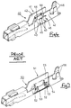
- FIG. 6 of the accompanying drawings shows a conventional pressure contact terminal fitting.
- a terminal fitting 40 has two pairs of pressure contact blades 45, formed anteriorly and posteriorly, and located inside a pressure contact member 41 whose upper face is open and forms a channel, facing side walls 42 thereof being sheared out so as to form a pair of mutually facing protruding members 43 which constitute the pressure contact blades 45.
- a pressure contact groove 44 is formed between the protruding members 43.
- the reason for providing two pairs of blades 45 is that the core wire normally consists of a plurality of thin intertwined wires, and providing only pair of blades 45 can result in the core wire becoming unwound after making pressure contact, and this can cause the core wire to escape the groove 44 or otherwise reduce the electrical contacting force. If two pairs of pressure contact blades 45 are provided, the unwinding and poor contact are prevented from occurring, and the reliability of the electric contact increases.
- the protruding members 43 which form the pressure contact blades 45 are sheared out from the side plates 42.
- the sides walls 42 are formed in a unified manner with barrels 46 which serve to fix the electric wire by being crimped around the posterior end of the pressure contact portion of the electric wire. Consequently, due to the barrels 46 being crimped, the side walls 42 have a tendency to change shape by bending, resulting in a slight change in the width of the pressure contact groove 44. This adversely affects the reliability of the pressure contact.
- FIG. 7 shows a different type of prior pressure contact terminal fitting.
- a terminal fitting 50 has two pressure contact blades 53 formed anteriorly and posteriorly by shearing out of a base plate 54 of a pressure contact member 51, the blades 53 having pressure contact grooves 52 formed thereon.
- the pressure contact blades 53 are cut out from the base plate 54, even if the side walls 55 bend in accompaniment with the crimping by the barrel 56, the accuracy of the dimension of the pressure contact grooves 52 remains unaffected by the bending, resulting in a higher reliability of contact compared to the terminal fitting 40 of Figure 6.
- the two pressure contact blades 53 are sheared out from the base plate 54, there is a problem in that the total length of the base plate 54, that is, the length of the terminal fitting 50, becomes larger than that of the other prior terminal fitting 40.
- Both the terminal fitting 40 of Figure 6 and the terminal fitting 50 of Figure 7 have their own advantages and shortcomings; consequently a further improvement seems desirable.
- the present invention has been developed after taking the above problems into consideration, and aims to maintain a short length while achieving a highly reliable pressure contact.
- a pressure contact terminal fitting comprising a base and two upstanding side walls defining a channel, and a crimping barrel at one end of said channel, the terminal fitting further including two pairs of opposed blades adapted to receive an electrical wire, a first pair of said blades being nearer said crimping barrel and part-sheared out of said base, and a second pair of said blades being further from said crimping barrel and part-sheared one each out of said side walls.
- Such a terminal fitting has the advantage that the rearmost blades (adjacent the crimping barrel) are not susceptible to deformation when the crimping barrel is crimped. Furthermore the frontmost blades are sheared out of respective side walls which keeps the terminal short whilst also distributing the consequent apertures around the terminal. This latter advantage contributes to the reduction in localised stress and gives a balanced distribution through the terminal.
- the rearmost blades are bent up towards the crimping barrel whereas the front most blades are bent in away from the crimping barrel.
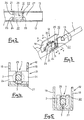
- Figure 1 is a diagonal view of a first embodiment showing a state prior to the insertion of a wire.
- Figure 2 is a partial plan view of the first embodiment.
- Figure 3 is a diagonal view of the first embodiment showing an inserted wire.
- Figure 4 is a cross-sectional view along the line X-X in Figure 3.
- Figure 5 is a cross-sectional view along the line Y-Y in Figure 3.
- Figure 6 is a diagonal view of a prior art connector.
- Figure 7 is a diagonal view of another prior art connector.
- the present embodiment applies to a female pressure contact terminal fitting formed by first cutting and then shaping an electrically conductive metal plate into the configuration shown in Figure 1.
- the terminal fitting 10 comprises, in sequence from the anterior end towards the posterior end: a connecting member 11 which connects with a corresponding male terminal fitting (not shown); a pressure contact member 12 whose upper face is open, forming a groove shape, the pressure contact member 12 making pressure contact with a terminal end of an electric wire 1; and barrels 13 for crimping to the posterior end of the pressure contact portion of the electric wire 1.
- the connecting member 11 provided at the anterior end has an angular tube shape with a two-layered roof face. Its interior has a resilient contact member 15 that can make contact in a resilient manner with a tab member of a corresponding male terminal fitting. Further, a lance 16 is formed by cutting away the roof face. When the terminal fitting 10 is inserted into a cavity of a connector housing (not shown), the lance 16 is stopped by a stopping member located inside the cavity, and the terminal fitting 10 is retained in an unremovable state. Along with this, one edge of the roof face has a stabilizer 17 for preventing the terminal fitting 10 from being inserted the wrong way and for maintaining a stable insertion in a housing (not shown).
- the barrels 13 are provided as a pair at the rear end so as to protrude upwards from side walls 20 which extend from side walls 19 of the pressure contact member 12.
- the barrels 13 are slightly displaced with respect to each other in an anterior-posterior direction.
- the pressure contact member 12 has pressure contact blades 21 and 22 located in the anterior and posterior. As shown in Figure 4, the anteriorly located pressure contact blades 21 are formed by part-shearing inwards a pair of protruding members 24 which extend from mutually facing left and right side walls 19 of the pressure contact member, the protruding members 24 facing each other. A pressure contact groove 25 is formed between the protruding edges of the protruding members 24. The width of the pressure contact groove 25 is set at a specified dimension that is somewhat smaller than the diameter of a core wire 3 of the electric wire 1.
- the pressure contact blade 22 located in the posterior is formed by part-shearing it out from the base plate 27 of the pressure contact member 12 with a pressure contact groove 29 already formed on the pressure contact blade 22.
- the base end of the pressure contact blade 22 is then bent so that the pressure contact blade 22 faces up at a right angle with respect to its original position. A specified distance is maintained with respect to the anteriorly located pressure contact blades 21.
- the width of the pressure contact groove 29 in the pressure contact blade 22 is the same as that of the pressure contact groove 25 of the anterior pressure contact blade 21.
- the terminal end of the electric wire 1 is inserted towards the pressure contact blades 21 and 22 from the upper face of the terminal fitting 10.
- a covering 2 of the electric wire 1 is cut into by the edges of the pressure contact grooves 25 and 29, and the core wire 3 makes contact with the edges of the pressure contact grooves 25 and 29.
- the electric wire 1 and the terminal fitting 10 make electrical contact via the two pressure contact blades 21 and 22 located in the anterior and posterior.
- the pair of barrels 13 provided at the posterior of the pressure contact member 12 are crimped onto the electric wire 1 so as to surround it. As shown in Figure 3, this results in the terminal fitting 10 becoming fixed with respect to the electric wire 1.
- the accuracy of the dimension of the pressure contact groove 29 is high from the very outset since it is formed beforehand in the posteriorly located pressure contact blade 22 by shearing away the base plate 27. Furthermore, since the pressure contact blades 21 are formed by shearing away the protruding members 24 from the left and right side plates 19, and since the pressure contact blades 21 are located towards the anterior and at a distance from the barrels 13, when the barrels 13 are crimped, the side plates 19 remain unaffected by the bending of the barrels 13, and the dimension of the pressure contact groove 25 remains relatively accurate. In this manner, a highly reliable pressure contact can be maintained for the electric wire 1.
- the pressure contact blades 21 and 22 are formed separately by cutting away from the side plates 19 and the base plate 27, compared to the case where two pressure contact blades are sheared out from the base plate 27, the length of the pressure contact member 12, that is, the length of the terminal fitting 10, can be made shorter. Furthermore, the openings 30 and 31, formed after shearing out away the pressure contact blades 21 and 22, are distributed between the side plates 19 and the base plate 27, thereby maintaining a balanced strength with respect to the pressure contact member 12.
Abstract
Description
Claims (5)
- A pressure contact terminal fitting comprising a base (27) and two upstanding side walls (19,20) defining a channel, and a crimping barrel (13) at one end of said channel, the terminal fitting further including two pairs of opposed blades (21,22) adapted to receive an electrical wire, a first pair of said blades (22) being nearer said crimping barrel and part-sheared out of said base (27), and a second pair of said blades (21) being further from said crimping barrel and part-sheared one each out of said side walls (19,20).
- A fitting according to claim 1 wherein said first pair of said blades (22) are comprised of an upstanding planar member having an open ended slot (29) formed in the end thereof.
- A fitting according to claim 2 wherein said first pair of said blades (22) is bent out of said base (27) in the direction towards said crimping barrel (13).
- A fitting according to any preceding claim wherein each blade of said second pair of blades (21) is bent out of a respective side wall (19,20) in the direction away from said crimping barrel (13).
- A fitting according to any preceding claim wherein said second pair of blades (21) are substantially identical.
Applications Claiming Priority (2)
| Application Number | Priority Date | Filing Date | Title |
|---|---|---|---|
| JP314950/96 | 1996-11-26 | ||
| JP8314950A JPH10154535A (en) | 1996-11-26 | 1996-11-26 | Pressure contact type terminal metal fitting |
Publications (2)
| Publication Number | Publication Date |
|---|---|
| EP0844688A2 true EP0844688A2 (en) | 1998-05-27 |
| EP0844688A3 EP0844688A3 (en) | 1999-05-12 |
Family
ID=18059620
Family Applications (1)
| Application Number | Title | Priority Date | Filing Date |
|---|---|---|---|
| EP97308714A Withdrawn EP0844688A3 (en) | 1996-11-26 | 1997-10-30 | Pressure contact terminal fitting |
Country Status (4)
| Country | Link |
|---|---|
| US (1) | US6007365A (en) |
| EP (1) | EP0844688A3 (en) |
| JP (1) | JPH10154535A (en) |
| CN (1) | CN1183658A (en) |
Cited By (2)
| Publication number | Priority date | Publication date | Assignee | Title |
|---|---|---|---|---|
| US6296512B1 (en) | 1999-08-18 | 2001-10-02 | Yazaki Corporation | Press-connecting terminal |
| EP1530266A2 (en) * | 2003-11-07 | 2005-05-11 | J.S.T. Mfg. Co., Ltd. | Socket connector |
Families Citing this family (16)
| Publication number | Priority date | Publication date | Assignee | Title |
|---|---|---|---|---|
| FR2782195B1 (en) * | 1998-08-07 | 2003-08-08 | Entrelec Sa | SELF-STRIPPING CONNECTION PIECE |
| JP3672763B2 (en) * | 1999-04-26 | 2005-07-20 | 矢崎総業株式会社 | Pressure contact terminal fitting |
| JP3585103B2 (en) * | 1999-09-17 | 2004-11-04 | 矢崎総業株式会社 | Wiring board |
| JP2001110466A (en) * | 1999-10-04 | 2001-04-20 | Yazaki Corp | Crimping connector |
| JP2001143774A (en) | 1999-11-12 | 2001-05-25 | Yazaki Corp | Pressure contact terminal |
| JP2001229988A (en) * | 2000-02-21 | 2001-08-24 | Yazaki Corp | Pressure-welded terminal |
| JP3797539B2 (en) * | 2000-09-14 | 2006-07-19 | 株式会社オートネットワーク技術研究所 | Method of forming connector pressure contact |
| JP3875864B2 (en) * | 2001-09-18 | 2007-01-31 | 矢崎総業株式会社 | Terminal fitting |
| ATE369636T1 (en) * | 2005-01-19 | 2007-08-15 | Alcatel Lucent | GROUNDING DEVICE FOR CABLES WITH CABLE SHEATH |
| CN102414871B (en) * | 2009-08-18 | 2015-03-04 | 矢崎总业株式会社 | Power-supply device and battery connector |
| DE102012103599A1 (en) * | 2012-04-24 | 2013-10-24 | Wago Verwaltungsgesellschaft Mbh | Insulation displacement connector for connecting with circuit board and for attaching electric conductor, has overload protection device to suppress the movement of spring element along extending direction of cutting edge portion |
| JP6062212B2 (en) * | 2012-11-02 | 2017-01-18 | 矢崎総業株式会社 | Electric wire with terminal and method for manufacturing electric wire with terminal |
| JP6183665B2 (en) * | 2015-08-05 | 2017-08-23 | 住友電装株式会社 | Terminal |
| US9793634B2 (en) | 2016-03-04 | 2017-10-17 | International Business Machines Corporation | Electrical contact assembly for printed circuit boards |
| KR102249929B1 (en) * | 2017-03-01 | 2021-05-11 | 몰렉스 엘엘씨 | Electrical terminals and connector assemblies |
| TWI754961B (en) * | 2019-12-18 | 2022-02-11 | 大陸商東莞訊滔電子有限公司 | Connector |
Citations (3)
| Publication number | Priority date | Publication date | Assignee | Title |
|---|---|---|---|---|
| US4693532A (en) * | 1985-02-04 | 1987-09-15 | Molex Incorporated | Modular staggered multi-row electrical connector |
| WO1990005392A1 (en) * | 1988-11-11 | 1990-05-17 | Amp Incorporated | Electrical contact |
| US5380218A (en) * | 1992-09-11 | 1995-01-10 | Yazaki Corporation | Pressure-contact terminal structure |
Family Cites Families (5)
| Publication number | Priority date | Publication date | Assignee | Title |
|---|---|---|---|---|
| JPH0451426Y2 (en) * | 1988-10-12 | 1992-12-03 | ||
| JP2559818Y2 (en) * | 1990-12-10 | 1998-01-19 | 日本エー・エム・ピー株式会社 | Pressure contact type |
| US5133672A (en) * | 1991-08-09 | 1992-07-28 | Molex Incorporated | Insulation displacement terminal |
| JP2848514B2 (en) * | 1994-03-29 | 1999-01-20 | 矢崎総業株式会社 | Crimp terminal for stranded wire |
| JP2929423B2 (en) * | 1994-12-08 | 1999-08-03 | 矢崎総業株式会社 | ID terminal |
-
1996
- 1996-11-26 JP JP8314950A patent/JPH10154535A/en active Pending
-
1997
- 1997-10-30 EP EP97308714A patent/EP0844688A3/en not_active Withdrawn
- 1997-11-18 CN CN97120182.XA patent/CN1183658A/en active Pending
- 1997-11-25 US US08/978,284 patent/US6007365A/en not_active Expired - Lifetime
Patent Citations (3)
| Publication number | Priority date | Publication date | Assignee | Title |
|---|---|---|---|---|
| US4693532A (en) * | 1985-02-04 | 1987-09-15 | Molex Incorporated | Modular staggered multi-row electrical connector |
| WO1990005392A1 (en) * | 1988-11-11 | 1990-05-17 | Amp Incorporated | Electrical contact |
| US5380218A (en) * | 1992-09-11 | 1995-01-10 | Yazaki Corporation | Pressure-contact terminal structure |
Cited By (3)
| Publication number | Priority date | Publication date | Assignee | Title |
|---|---|---|---|---|
| US6296512B1 (en) | 1999-08-18 | 2001-10-02 | Yazaki Corporation | Press-connecting terminal |
| EP1530266A2 (en) * | 2003-11-07 | 2005-05-11 | J.S.T. Mfg. Co., Ltd. | Socket connector |
| EP1530266A3 (en) * | 2003-11-07 | 2007-03-07 | J.S.T. Mfg. Co., Ltd. | Socket connector |
Also Published As
| Publication number | Publication date |
|---|---|
| CN1183658A (en) | 1998-06-03 |
| EP0844688A3 (en) | 1999-05-12 |
| JPH10154535A (en) | 1998-06-09 |
| US6007365A (en) | 1999-12-28 |
Similar Documents
| Publication | Publication Date | Title |
|---|---|---|
| US6007365A (en) | Pressure contact terminal fitting | |
| EP0337659B1 (en) | Solder post retention means | |
| EP0572874B1 (en) | Dual thickness blade type electrical terminal | |
| US5662487A (en) | Connector | |
| US4472017A (en) | Tab receptacle terminal | |
| US6439935B2 (en) | Female terminal fitting | |
| CA1067595A (en) | Electrical terminal stamped and formed from a single piece of sheet metal stock | |
| JPH05307983A (en) | Electric connect terminal | |
| US4527852A (en) | Multigauge insulation displacement connector and contacts therefor | |
| EP0099145B1 (en) | Rib cage terminal | |
| EP0795930B1 (en) | High contact force pin-receiving electrical contact | |
| US4448477A (en) | Electric socket terminal | |
| EP0920082A1 (en) | Terminal fitting and waterproof connector | |
| US4298242A (en) | Electrical socket contact | |
| US5711067A (en) | Method of forming electrical connector | |
| US4373769A (en) | Electrical connector including insulation-opening contact | |
| EP0101290B1 (en) | Multigauge insulation displacement connector and contacts therefor | |
| EP0845836B1 (en) | Terminal fitting | |
| EP0171193A2 (en) | Duplex sheet metal insulation displacement terminal | |
| US6080005A (en) | Terminal fitting | |
| US6443754B2 (en) | Pressure connecting terminal | |
| JP3082613B2 (en) | Female terminal fitting | |
| JP3087617B2 (en) | Electrical junction box with insulation displacement terminals | |
| JP2801774B2 (en) | Receptacle terminal having fixing means | |
| EP0702430B1 (en) | Polarized terminals and electrical connector comprising such terminals |
Legal Events
| Date | Code | Title | Description |
|---|---|---|---|
| PUAI | Public reference made under article 153(3) epc to a published international application that has entered the european phase |
Free format text: ORIGINAL CODE: 0009012 |
|
| 17P | Request for examination filed |
Effective date: 19971114 |
|
| AK | Designated contracting states |
Kind code of ref document: A2 Designated state(s): DE FR GB IT |
|
| PUAL | Search report despatched |
Free format text: ORIGINAL CODE: 0009013 |
|
| AK | Designated contracting states |
Kind code of ref document: A3 Designated state(s): AT BE CH DE DK ES FI FR GB GR IE IT LI LU MC NL PT SE |
|
| AKX | Designation fees paid |
Free format text: DE FR GB IT |
|
| STAA | Information on the status of an ep patent application or granted ep patent |
Free format text: STATUS: THE APPLICATION HAS BEEN WITHDRAWN |
|
| 18W | Application withdrawn |
Withdrawal date: 20020225 |