BACKGROUND OF THE INVENTION
It is well known to provide refrigeration
and/or controlled atmospheres to maintain the freshness
of perishable agricultural products, such as fruits,
vegetables and flowers during storing or shipping of the
same. In this connection, it is also well known that it
is desirable to avoid freezing the products to prevent
damage and deterioration, and that a large number of
perishable products may be maintained in fresher condition
at above-freezing refrigerated temperatures when
they are also maintained in a low oxygen/high carbon
dioxide content atmosphere, which is known to be less
conducive to rapid ripening and spoilage. The maintenance
of such a controlled atmosphere typically requires
an air-tight seal of a refrigerated enclosure, which
necessarily limits access to the agricultural products
during storage and transport. It is also known to
utilize a controlled atmosphere to store hardware such as
guns or machinery.
BRIEF SUMMARY OF THE INVENTION
The essence of the present invention comprises
the provision of a multiplicity of open-ended chambers
within an enclosure which may or may not be refrigerated,
the chambers being of sufficient size to accommodate one
or more pallets bearing standard-sized containers such as
produce containers wherein each chamber is further
provided with detachable closure means capable of either
covering the open end of the chamber or dividing the
chamber into discrete zones or reducing the size of the
chamber and with a means for gas circulation and appropriate
hardware to receive and maintain a controlled
atmosphere from a controlled atmosphere supply. When
used for the storage of produce, the chambers are
preferably within a refrigerated enclosure.
BRIEF DESCRIPTION OF THE SEVERAL VIEWS OF THE DRAWING
FIG. 1 is a perspective overview of the
controlled atmosphere container system of the present
invention, showing a plurality of individual open-ended
chambers within a refrigerated enclosure.
FIG. 2 is a side view of one of the open-ended
chambers shown in FIG. 1.
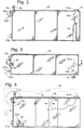
FIG. 3 is a top view of one of the open-ended
chambers.
FIG. 4 is a cross-sectional view of FIG. 3
taken along the plane 4-4.
FIG. 5 is a cross-sectional detailed view of
that portion of FIG. 4 designated as 5.
FIG. 6 is a cross-sectional view of element 18
of FIG. 5 taken along the plane 6-6.
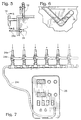
FIG. 7 is an illustration of a portion of an
exemplary combination gas monitoring and control system.
DETAILED DESCRIPTION OF THE INVENTION
According to the present invention, there is
provided a controlled atmosphere container system
comprising:
Each chamber is built of a rigid gas-impermeable material
such as sheet metal, fiberglass, thermosetting polymer or
even wood with a sealant applied thereto; in a preferred
embodiment, the material is 14 ga. steel. To receive the
controlled atmosphere and to maintain the same, each
chamber is provided with removable or detachable closure
means such as a flexible curtain or a lightweight partition
capable of covering the open end of the chamber and
reducing the effective size of the chamber, an inert gas
inlet, a pressure relief valve, exhaust means, gas circulating
means and gas composition testing means. Such an
arrangement allows storage of a wide variety of agricultural
and hardware products having different controlled
atmosphere composition requirements for storage and/or
shipment, allows far more flexible access to the stored
items without concern for breaking the controlled atmosphere
seal, and at the same time minimizes the volumetric
flow requirements for the supply and maintenance of a
controlled atmosphere. In the case of stored produce, a
wide variety of produce having different controlled
atmosphere requirements may be stored in the same refrigerated
enclosure while permitting access to selected
produce without risk of spoilage of other stored produce.
In an especially preferred embodiment, the
detachable closure means is substantially gas-impermeable
plastic sheeting, sail cloth-grade ripstock nylon,
treated canvas or a plexiglass sheet that may be sealed
either to the open end of the chamber or to the sides,
top and bottom of the chamber at some point inward of the
open end so as to reduce the effective size of the
chamber. The detachable closure is also preferably
transparent so as to allow observation of the condition
of the produce therethrough, although non-transparent
material such as plywood or even light gauge steel will
function as well. The detachable closure may be
supported by a lightweight rigid frame of, e.g., wood,
PVC, ABS, aluminum, or other lightweight metal or alloy,
or it may be unsupported. Because the detachable closure
is not a permanent structure, the same may simply be
disposed of when it becomes worn or soiled.
To supply each chamber with a controlled
atmosphere, each chamber is provided with an inert gas
inlet that is fed by a source of one or more inert gases,
the source preferably being valved. Typically, such
inert gases include nitrogen, argon, carbon dioxide and
ethylene, with nitrogen being used for flushing the
chamber to rid it of atmospheric air and carbon dioxide,
the latter being used in the case of produce storage to
supply the bulk of the controlled atmosphere. The inert
gas inlet may be as simple as a slit or hole in the
detachable closure means of sufficient size to receive a
gas hose therethrough.
Flushing of the chamber takes place by securing
the closure means to four walls of the chamber at a
predetermined point, preferably sealing the same thereto
by tape, opening the purge valve in the top of the
chamber and flushing atmospheric air out with an inert
gas such as nitrogen, then closing the purge valve and
feeding the inert gas into the chamber until the chamber
contains the desired controlled atmosphere composition,
as indicated by gas composition testing means.
The chamber experiences variations in
atmospheric pressure, which variations in turn produce
fluctuations in the pressure of the controlled atmosphere
within the chamber. These pressures are accommodated by
an exhaust valve provided in the upper portion of the
chamber which, for economy of installation, is preferably
a simple water-filled trap that generally prevents the
entry of atmospheric air into the chamber, yet allows the
escape of controlled atmosphere gases upon a build-up in
pressure of the same within the chamber.
To allow the perishable produce to be in
contact with the controlled atmosphere, each chamber is
provided with gas circulating means, which is preferably
a fan inside the chamber and duct work outside the
chamber.
Each chamber is also preferably provided with
humidification and/or dehumidification means so as to
allow an increase or a reduction in the humidity in the
chamber, some of the humidity being caused by respiration
when produce is stored. The humidification/
dehumidification means is preferably within the duct work
outside the chamber, and includes secondary gas
circulation means such as a fan.
Each chamber is also preferably provided with a
gas composition tester that is in fluid communication
with a gas composition monitor and in further communication
with a supply of inert gas, the arrangement acting
in cooperation to allow precise monitoring and adjustment
of the controlled atmosphere to suit the particular
storage needs of the produce in the chamber.
Turning now to the drawings, wherein like
numerals refer to the same elements, there is shown in
FIG. 1 a perspective overview of the controlled atmosphere
container system of the present invention, showing
a plurality of individual open-ended chambers 10 within a
refrigerated enclosure 1, each chamber preferably being
spaced apart from the adjacent chamber so as to permit
circulation of refrigerated air between the chambers.
Each chamber 10 is sized so as to accommodate a single
layer of a number of pallets having standard-sized
containers such as produce containers on the pallets, and
also so as to accommodate a standard-sized lift truck of
the type used in moving goods in warehouses, or a
manually operated pallet lift or a person. Preferably,
the dimensions of each chamber are: from 5 to 8 feet in
height; multiples of 48 inches in length; and multiples
of 48-52 inches in width. When the system is used in a
refrigerated enclosure 1, the enclosure may be of the
type found in a warehouse, in a ship's cargo hold, in a
truck, in a rail car or in a modular cargo container.
Each chamber 10 is provided with detachable
closure means 12 such as a flexible curtain or a
lightweight partition, the closure means being capable of
being detachably attached to the four walls of the
chamber so as to substantially seal the same against the
intrusion of atmospheric air. In a preferred embodiment,
the removable closure means 12 is transparent or translucent
flexible or rigid plastic or nylon sheeting that
is capable of being sealed to the chamber 10 simply by
taping the same to the four walls of the open chamber.
In an especially preferred embodiment, the removable
closure means 12 comprises substantially gas-impermeable
sail cloth-grade ripstock nylon mounted on a lightweight
rigid frame. In the case of produce storage, transparency
allows one to view the produce to ascertain whether
any adverse conditions have developed, such as an infestation
of insects, undue respiration as indicated, for
example, by the build-up of condensation on the detachable
closure 12, or spoilage. When the closure becomes
unduly soiled or worn or torn, the same may simply be
disposed of and replaced with a fresh detachable closure.
In FIG. 2 there is shown a side view of one of
the chambers 10, revealing an inert gas inlet 14, inert
gas being supplied from an inert gas source such as a
pressurized tank 15 and fed to inlet 14 via inert gas
feed hose 15a. Alternatively, inert gas such as CO2 may
be supplied by warming liquid CO2 to a gaseous state,
accumulating and temporarily storing the gaseous CO2 in a
holding tank, then transforming a predetermined amount of
the gaseous CO2 to the chamber by an adjustable, timer-controlled
valve. Such an automatic delivery system may
be coupled with an adjustable, timer-controlled evacuation
pump to evacuate the chamber prior to charging it
with CO2, and to shut down the evacuation pump during the
CO2-charging cycle. Such a system is described in U.S.
Patent No. 4,843,956, the details of which are incorporated
herein. The inert gas inlet may also be nothing
more than a slit or a hole, sealable with tape, in
detachable closure 12, as shown in 12a of FIG. 4,
sufficient in size to accommodate a gas hose from the
inert gas supply. Typical inert gases used in the
storage of agricultural produce such as fruit, nuts,
vegetables and flowers include carbon dioxide, ethylene,
nitrogen and argon, with carbon dioxide being the inert
gas in most widespread use. Chamber 10 is provided with
a purge valve 16 so as to allow flushing of atmospheric
air from the chamber, valve 16 simply being opened when
the chamber is being purged of atmospheric air and closed
when the chamber is substantially purged. Proper storage
of most agricultural produce calls for the presence of a
minor amount of air, on the order of .05 to 20 vol%. In
order to achieve such a composition, atmospheric air may
be allowed to reenter the chamber merely by opening purge
valve 16. Alternatively, pure oxygen from an oxygen
source (not shown) may be supplied via gas inlet 14.
Because the interior of chamber 10 will
experience fluctuations in pressure depending upon atmospheric
pressure, each chamber is provided with exhaust
means 18 to allow the escape of gas upon a build-up of
pressure within the chamber. Preferably the exhaust
means 18 is a simple trap, best seen in FIGS. 5 and 6,
the trap being filled with a liquid such as water to form
a seal so as to both prevent the entry of atmospheric air
into chamber 10 and to prevent escape of the controlled
atmosphere other than as is necessary to prevent an undue
pressure reduction or build-up within the chamber.
As seen in FIG. 4, each chamber 10 is provided
with gas circulating means 20, which is preferably a
blower of some sort such as a fan. To further promote
circulation of the controlled atmosphere within
chamber 10, each chamber may also be provided with
ducting 21, shown in phantom in FIG. 4, to provide a
pathway for the circulation of the controlled atmosphere
from the top of the chamber to the chamber's bottom via
ports 21a and 21b. In the event no ducting 21 is used,
as would be the case when little circulation of the
controlled atmosphere is needed, ports 21a and 21b are
closed to atmospheric air by the insertion of bungs (not
shown). When ducting 21 is used, in order to prevent the
build-up of water vapor, ducting 21 may be provided with
dehumidification means 22, preferably comprising a
desiccant bed. Alternatively, humidification means (also
designated 22) may be provided as necessary to maintain
the proper level of humidity, the humidification means
preferably comprising a swap cooler or a mister. When a
chamber is provided with either humidification or
dehumidification means 22, the chamber is also preferably
provided with secondary gas circulating means, such
as a fan.
In order to periodically test the composition
of the controlled atmosphere within chamber 10, the
chamber is preferably provided with gas composition
testing means, comprising in combination a gas composition
sampler 24 connected to a gas analyzer 26 through
sampler line 24a through valve 24b and gas analyzer
line 24c. When a sample of the controlled atmosphere is
desired to be taken and analyzed, valve 24b is opened, a
vacuum is drawn by gas analyzer 26 upon line 24c and a
sample is thereby drawn into analyzer 26 and analyzed to
ascertain its precise make-up. An especially preferred
gas analyzer is one commercially available from Pacific
Ca Systems of Yakima, Washington. To the extent the
controlled atmosphere requires more inert gas, the same
may be either manually or automatically supplied from
pressurized tank 15. In the event that makeup gas is
supplied automatically, gas analyzer 26 is in electronic
communication with a servovalve (not shown) by means of a
computerized controller (not shown) in inert gas supply
line 15a, whereby the controller, in response to an electronic
signal from the gas analyzer that the concentration
of inert gas in chamber 10 has fallen below a
predetermined concentration, releases inert gas into the
chamber. As seen in FIG. 7, each chamber 10 may be
provided with its own gas composition testing means, with
each sample line being in fluid communication with a
common manifold feeding gas analyzer supply line 24c.
The system of the present invention is useable
for the storage and transportation of all manner of
goods, and is particularly well-suited for agricultural
produce, including fruits, nuts, vegetables, mushrooms
and flowers, and is capable of maintaining controlled
atmospheres of widely varying compositions of from as
little as .05 vol% oxygen to as high as 20 vol% and from
as little as 0.04 vol% carbon dioxide to as high as
99.9 vol%. A good tabulation of the composition of
controlled atmospheres for storage of various types of
produce is found in "Proceedings of the Fourth National
Controlled Atmosphere Research Conference," July 23-26,
1985, North Carolina State University, Raleigh, N.C. In
addition, the system of the present invention is capable
of maintaining multi-component controlled atmospheres,
simply by the addition of multiple inert gas inlet ports.
EXAMPLE
Freshly harvested blueberries containing about
1% unripe green berries and red berries were cleaned,
sorted, graded and packaged the same day into 6 oz.
hallocks placed in crates which were then loaded onto 6
standard-sized pallets, each measuring 40" wide x 48"
long x 72" in height. Each pallet was then precooled to
32°F and placed into a controlled atmosphere chamber
fabricated from 14 ga. steel and having substantially the
same design shown in FIGS. 2-4, with six pallets to each
chamber. The chambers were within a refrigerated
warehouse enclosure maintained at 32°F.
The open end of each chamber was sealed with
6-mil-thick clear polyethylene taped to the four walls of
the chamber. Purge valve 16 was opened, and atmospheric
air was flushed with nitrogen until the oxygen level
reached 8 vol%. Carbon dioxide was then supplied via
inert gas inlet 14 until its concentration reach 12 vol%.
The carbon dioxide also reduced the oxygen concentration
to 6 vol%. Interior fan 20 was turned on for slight gas
circulation within the chamber. The temperature in the
chambers stayed at 33-34°F.
The blueberries were so stored for a total of
45 days, with the atmosphere being monitored daily by
analyzer 26. The fruit was reinspected upon opening the
chambers and actually improved in overall grade due not
only to the total absence of decay, mold, mildew and
insect damage, but also to the ripening of 75% of the
green and red berries.
The terms and expressions which have been
employed in the foregoing specification are used therein
as terms of description and not of limitation, and there
is no intention in the use of such terms and expressions
of excluding equivalents of the features shown and
described or portions thereof, it being recognized that
the scope of the invention is defined and limited only by
the claims which follow.
The term "standard-sized container" used herein
is intended to denote a container having a size
commonplace in the industrial or commercial field
concerned.