BACKGROUND OF THE INVENTION
The present invention relates to diverter valves for diverting flow from an inlet to a
selected one of plural outlets. The invention particularly relates to such valves having
application in laundry appliances for distributing water to various locations in an automatic
clothes washer for dispensing detergent, fabric softener, bleach or other laundry additives.
In the competitive marketplace for automatic clothes washers and dishwashers for
household use, it has been desired to provide complete electrical/electronic control of the
appliance program and to provide user selection of various programs which are then
capable of being fully implemented automatically by the machine programmer controller.
Where it has been desired to provide the user with a selection of types of additives or the
sequence in which certain additives and functions are performed, it has been desired to
provide for performing the selection of these programs automatically by servoactuators
rather than requiring the user to individually position a control to perform the function
during the machine cycle.
Where it has been desired to provide for automatic dispensing of plural additives in
a laundry appliance, the need has arisen for a servo actuated valve for diverting water flow
to the various additive containment containers at the appropriate time during the appliance
program for dispensing the desired additive. Thus, it has been desired to provide a low
cost reliable way or means of electrically dispensing additives in a laundry appliance during
the appliance program cycle in a manner which is low in manufacturing cost and simple to
install during manufacture of the appliance and is reliable during the service life of the
appliance.
BRIEF SUMMARY OF THE INVENTION
It is an object of the present invention to provide a motor driven diverter valve
which is low in cost, simple to construct and easy to install for use in an automatically
programmed appliance.
It is a further object of the present invention to provide a low cost diverter valve
suitable for use in household laundry appliances and which provides for accurate
positioning of a valve member for directing flow to a selected one of plural outlets in
response to a relatively low power control signal.
The present invention provides a diverter valve utilizing a low cost synchronous
timing motor driving a rotary diverter valve through a speed reducing unit which is
compactly assembled on the valve body.
The present invention employs a low power requirement synchronous timing motor
driving a rotary cam member through a speed reducer which is disposed within the motor
housing. The housing includes a circuit board having plural cam actuated switches
disposed thereabout. The cam is journalled on a cover for the rotary valve member which
is disposed in a valving chamber in the valve body for directing flow from the single inlet
to a selected one of plural outlets. The motor and speed reducer with the switchboard and
cam are assembled as a subassembly and the valve body, valve member and cover and cam
are assembled as another subassembly; and, the motor/speed reducer subassembly is then
attached to the valve body subassembly. Upon energization the motor drives the valve
member to the selected position and the cam actuates a switch to disconnect power from
the motor once the valve is in the desired position.
BRIEF DESCRIPTION OF THE DRAWINGS
FIG 1 is an axonometric view of the assembled valve of the present invention;
FIG. 2 is a bottom view of the assembly of FIG. 1;
FIG 3 is a composite cross-section with features related to the picture plans for
purposes of illustration;
FIG 4 is an exploded view of the valve assembly of FIG. 1;
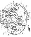
FIG.5 is an axonometric view of the underside of the circuit board of FIG. 4 taken
in the direction of the view indicating arrows 5-5 of FIG. 4.
DETAILED DESCRIPTION OF THE INVENTION
Referring to FIGS. 1 through 3, the motorized diverter valve assembly of the
present invention is indicated generally at 10 and includes a body indicated generally at 12
which has an inlet fitting 14 which has an inlet passage 16 therein which communicates
with an inlet port 18 formed in a valving chamber 20 formed in the body. The valving
chamber has a sidewall portion which, in the presently preferred practice of the invention
has a cylindrical configuration denoted by reference numeral 22 and which has a plurality
of outlet ports disposed therein in circumferentially spaced arrangement, which are
illustrated in FIG. 3 and denoted by reference numerals 24, 26. In the embodiment
illustrated in FIGS. 1 and 2, five outlet fittings are employed as denoted by reference
numerals 21, 23, 25, 27, 29 and each has a passage such as 24, 26 therein which passage is
ported to chamber wall 22 in circumferentially spaced arrangement. A rotary valving
member 28 has a generally inverted cup-shaped configuration with the radially extending
outlet port 30 formed therein which communicates with a selected one of the outlet ports
by rotation of the valve member 28 to a selected discrete rotational position as will
hereinafter be described in greater detail.
The valve member 28 has the axial face 32 of the open rim thereof provided with a
circumferential groove 34 therein in which is received a resilient annular seal member 36
for effecting a rotary seal of the valve member against a cylindrical rib 37 formed in the
valving chamber 20. The surface of the outlet port 30 of the valve member is configured
in a cylindrical arc to interfit in closely fitting arrangement with the cylindrical wall 22 of
the valving chamber; and, port 30 has a sealing member 31 for providing a moving seal
with cylindrical wall 22 with the seal 31 ring biased against wall 22 by a spring 33. Thus,
rotation of the valving member within chamber 20 is controlled by the registration of the
periphery 38 of the valve member in closely interfitting sliding registration with the
cylindrical wall 22 of the valving chamber 20. The outer peripheral face of port seal 31 is
moved in rotary sliding engagement with the cylindrical wall 22 of the valving chamber to
provide selected communication between inlet passage 16 and one of the outlet ports when
the valve member is rotated such that the outlet port 30 thereon is disposed to align with
one of the outlet ports.
The upper surface 40 of the valve member has a cylindrical recess 42 formed
therein into which is 41 received in driving engagement a stub shaft with a flat portion 44
of a rotary cam member 46. Cam member 46 has an enlarged diameter portion 48 of stub
shaft 41 journalled in a bore 50 formed in a cover 52 provided over the cylindrical wall 22
of the valving chamber 20. The enlarged diameter 48 of the stub shaft 41 has a
circumferential groove 56 formed therein which has a resilient annular seal 54 received
therein for providing a rotary seal between the surface 48 and the bore 50.
A wave spring 58 is provided between the undersurface of cover 52 and the upper
surface 40 of the valve member to bias the valve member against the chamber 20 and to
maintain effectiveness of the annular seal 36 between the valve member 28 and the valve
chamber 20.
Referring particularly to FIGS. 3 and 4, a motor housing 60 has an upper chamber
or open cavity 62 with a cylindrical wall 64 which is integrally formed with a deck 66
which has on the undersurface thereof a second cylindrical wall portion 68 which defines a
downwardly facing open cavity 70. In the presently preferred practice cylindrical wall 68
is offset from the cylindrical wall 64 of the upper chamber to facilitate the motor drive as
will hereinafter be described.
The deck 66 has formed therein an aperture 72 for permitting connection to cam
46. The cylindrical wall 68 of housing 60 has a plurality of downwardly extending
projections formed integrally therewith comprising snap lock tabs denoted by reference
numeral 74 and which serve to snap over and engage correspondingly located lugs 77
provided on the body 12.
The upper housing chamber 62 has received therein a suitable mounting structure
comprising a support plate 76 and a motor frame 78 which has therein a secondary frame
portion denoted by reference numeral 80 which is attached to frame 78.
Referring to FIG. 3, a motor coil bobbin 82 is received in the motor frame 78 and
has wound thereon a plurality of turns of electrical conductor 84 to provide the motor field
windings. A rotor indicated generally at 86 is journalled on a shaft or pin 88 which has its
upper end mounted in the motor frame 78 upper surface and its lower end mounted in
deck plate 76. The motor rotor 86 includes a permanently magnetized armature 90 which
may be of ferrite powder filled resin material and is mounted on a rotor bushing 92 which
has formed thereon a motor drive pinion 94.
Motor drive pinion 94 engages a first stage pinion gear 96 which is journalled on
shaft or pin 98 which has its lower end mounted in deck plate 76 and its upper end in the
secondary deck 80. The first stage gear 96 has provided on its hub a first stage pinion 100
which engages a second stage gear 102 which is journalled on a pin 104 having its upper
end secured in motor deck 80 and its lower end attached to deck plate 76.
The second stage gear 102 has provided thereon a second stage pinion 106 which
engages a third stage gear 108 journalled on a pin or shalt 110 secured in deck plate 76.
Third stage gear 108 has provided thereon a third stage pinion, a portion of which is
visible in FIG. 3 and denoted by reference numeral 114 and which engages an output gear
116. The output gear 116 is journalled at the upper end of its hub 118 by a pin 120
received in the motor frame portion 80; and, the lower end of gear 116 has a hub 122
which is journalled in a flange formed in the deck plate 76 which extends into aperture 72.
The hub 122 of the output gear 116 has at least one driving surface 124 formed
thereon for engaging a corresponding surface 125 (see also FIG. 4) in the hub 126 of cam
rotor 46. In the presently preferred practice of the invention, the driving engagement
surface 124 comprises an external spline formed on hub 122 and an internal spline 125
formed in the hub 126 of cam rotor 46.
Referring to FIG. 5, a switch assembly indicated generally at 128 comprises a
circuit board 130 which has a plurality of switches indicated generally at 132, 134, 136,
138, 140 and a plurality of connector terminals 164 which are interconnected to the
switches by connector strips on the circuit board which are not visible in FIG. 5 as they are
on the underside of the board with respect to FIG. 5.
Each of the switches 132 through 140 has a contact blade 142 through 150
respectively each of which has the end thereof disposed to follow cam 46 which has a
notch 151 formed therein with the end of contact blade 150 shown dropped into the notch
in FIG. 5. Each of the contact blades 142 through 150 has provided thereon a double
sided electrical contact as denoted by reference numeral 152 through 160. Each of the
switches 132 through 140, also has a pair of oppositely disposed side contact denoted
respectively 132a, 132b, 134a, 134b, 136a, 136b, 138a, 138b, and 140a, 140b which are
mounted respectively on brackets 132', 132'', 134', 134'', 136', 136'', 138', 138'' and 140',
140''. Each of the brackets has a generally right angular configuration and is secured to the
board 130 by tabs 162 provided thereon which extend through the board 130 and are
soldered to the printed circuit on the underside thereof with respect to FIG. 5. Tabs 162
are not visible in FIG. 5, but are shown in FIG. 4. In similar fashion, each of the contact
blades 142 through 150 has the end thereof formed to a generally right angle configuration
with tabs 162 provided thereon which extend through the circuit board and are soldered to
strips provided thereon on the underside with respect to FIG. 5. With reference to FIG. 4,
various protruding portions of these tabs 162 are shown extending through the circuit
board to the upper surface thereof in FIG. 4. These tabs denoted by reference numeral
162 in FIG. 4 are soldered to the desired interconnecting strips (not shown) provided on
the upper surface of the board 130.
In operation the cam surface 46 is set to maintain each of the switches 132 through
150 such that the contact blades 142 through 160 respectively are moved to close one of
the side contacts associated respectively therewith; and, the cam notch 151 permits the end
of a contact blade, for example contact blade 150, to drop therein causing the closed side
contact to become open and the open contact to become closed in the manner of a single
pole double throw (SPDT) switch.
Referring to FIG. 5, the contact blade 150 has its end dropped into cam notch 151
such that contact is broken between contact 160 and side contact 140b; and, contact has
been made between the moveable contact 160 and the side contact 140a. Each of the
switches 132 through 150 is electrically connected such that when the cam notch 151 is
positioned to cause the respective contact blade to move, thereby opening the normally
closed set of contacts, current flow to the motor is stopped and rotation of the shaft 48 is
stopped. The valve member 28 is thus positioned such that the outlet port 30 is aligned
with one of the outlet ports 21-29 in the body corresponding to the desired valve function.
An electronic controller (not shown) may be employed to bypass the open switch to the
motor and restart the motor to cause rotation of the cam 46 to the next switch position,
for example, to switch 132 and once again the motor current will be stopped when the end
of the contact blade 142 drops into notch 151 thereby positioning the outlet port 30 on
rotor 28 to a different one of the outlets 21 through 29. Each of the switches 132 through
140 is connected to appropriate ones of terminal pins 164 provided in a receptacle 166
mounted on the board 130, which pins are adapted for connection to an external wiring
harness connector (not shown).
In manufacture, the switch and circuit board assembly 128 is assembled into the
cavity 70 on the motor housing as a subassembly and has the cam 46 preassembled thereon
such that the stub shaft 41 is received in the aperture 50 in cover 52 and extends
downwardly therethrough to engage the drive surface 42 in the valve member 28.
The motor housing upper chamber 62 has a cover 168 received thereover and
engaged therewith by any suitable expedient as for example snap locking into tabs 170
provided in the upper rim of cylindrical wall 64.
The present invention thus provides a compact easy to manufacture and assemble
and relatively low cost motorized diverter valve which has particular suitability for use in
household automatic washing machines.
Although the present invention has been described hereinabove with respect to the
illustrated embodiments, it will be understood that the invention is capable of modification
and variation and is limited only by the scope of the following claims.