EP0844380A2 - Exhaust emission control system and method of internal combustion engine - Google Patents
Exhaust emission control system and method of internal combustion engine Download PDFInfo
- Publication number
- EP0844380A2 EP0844380A2 EP97120579A EP97120579A EP0844380A2 EP 0844380 A2 EP0844380 A2 EP 0844380A2 EP 97120579 A EP97120579 A EP 97120579A EP 97120579 A EP97120579 A EP 97120579A EP 0844380 A2 EP0844380 A2 EP 0844380A2
- Authority
- EP
- European Patent Office
- Prior art keywords
- engine
- injection
- post
- exhaust gas
- oxygen
- Prior art date
- Legal status (The legal status is an assumption and is not a legal conclusion. Google has not performed a legal analysis and makes no representation as to the accuracy of the status listed.)
- Granted
Links
Images










Classifications
-
- F—MECHANICAL ENGINEERING; LIGHTING; HEATING; WEAPONS; BLASTING
- F02—COMBUSTION ENGINES; HOT-GAS OR COMBUSTION-PRODUCT ENGINE PLANTS
- F02D—CONTROLLING COMBUSTION ENGINES
- F02D41/00—Electrical control of supply of combustible mixture or its constituents
- F02D41/0025—Controlling engines characterised by use of non-liquid fuels, pluralities of fuels, or non-fuel substances added to the combustible mixtures
- F02D41/0047—Controlling exhaust gas recirculation [EGR]
- F02D41/0065—Specific aspects of external EGR control
-
- B—PERFORMING OPERATIONS; TRANSPORTING
- B01—PHYSICAL OR CHEMICAL PROCESSES OR APPARATUS IN GENERAL
- B01D—SEPARATION
- B01D53/00—Separation of gases or vapours; Recovering vapours of volatile solvents from gases; Chemical or biological purification of waste gases, e.g. engine exhaust gases, smoke, fumes, flue gases, aerosols
- B01D53/34—Chemical or biological purification of waste gases
- B01D53/92—Chemical or biological purification of waste gases of engine exhaust gases
- B01D53/94—Chemical or biological purification of waste gases of engine exhaust gases by catalytic processes
- B01D53/9495—Controlling the catalytic process
-
- F—MECHANICAL ENGINEERING; LIGHTING; HEATING; WEAPONS; BLASTING
- F01—MACHINES OR ENGINES IN GENERAL; ENGINE PLANTS IN GENERAL; STEAM ENGINES
- F01N—GAS-FLOW SILENCERS OR EXHAUST APPARATUS FOR MACHINES OR ENGINES IN GENERAL; GAS-FLOW SILENCERS OR EXHAUST APPARATUS FOR INTERNAL-COMBUSTION ENGINES
- F01N3/00—Exhaust or silencing apparatus having means for purifying, rendering innocuous, or otherwise treating exhaust
- F01N3/08—Exhaust or silencing apparatus having means for purifying, rendering innocuous, or otherwise treating exhaust for rendering innocuous
- F01N3/10—Exhaust or silencing apparatus having means for purifying, rendering innocuous, or otherwise treating exhaust for rendering innocuous by thermal or catalytic conversion of noxious components of exhaust
- F01N3/18—Exhaust or silencing apparatus having means for purifying, rendering innocuous, or otherwise treating exhaust for rendering innocuous by thermal or catalytic conversion of noxious components of exhaust characterised by methods of operation; Control
- F01N3/20—Exhaust or silencing apparatus having means for purifying, rendering innocuous, or otherwise treating exhaust for rendering innocuous by thermal or catalytic conversion of noxious components of exhaust characterised by methods of operation; Control specially adapted for catalytic conversion
-
- F—MECHANICAL ENGINEERING; LIGHTING; HEATING; WEAPONS; BLASTING
- F02—COMBUSTION ENGINES; HOT-GAS OR COMBUSTION-PRODUCT ENGINE PLANTS
- F02D—CONTROLLING COMBUSTION ENGINES
- F02D35/00—Controlling engines, dependent on conditions exterior or interior to engines, not otherwise provided for
- F02D35/0015—Controlling engines, dependent on conditions exterior or interior to engines, not otherwise provided for using exhaust gas sensors
- F02D35/0046—Controlling fuel supply
- F02D35/0092—Controlling fuel supply by means of fuel injection
-
- F—MECHANICAL ENGINEERING; LIGHTING; HEATING; WEAPONS; BLASTING
- F02—COMBUSTION ENGINES; HOT-GAS OR COMBUSTION-PRODUCT ENGINE PLANTS
- F02D—CONTROLLING COMBUSTION ENGINES
- F02D41/00—Electrical control of supply of combustible mixture or its constituents
- F02D41/02—Circuit arrangements for generating control signals
- F02D41/021—Introducing corrections for particular conditions exterior to the engine
- F02D41/0235—Introducing corrections for particular conditions exterior to the engine in relation with the state of the exhaust gas treating apparatus
-
- F—MECHANICAL ENGINEERING; LIGHTING; HEATING; WEAPONS; BLASTING
- F02—COMBUSTION ENGINES; HOT-GAS OR COMBUSTION-PRODUCT ENGINE PLANTS
- F02D—CONTROLLING COMBUSTION ENGINES
- F02D41/00—Electrical control of supply of combustible mixture or its constituents
- F02D41/02—Circuit arrangements for generating control signals
- F02D41/14—Introducing closed-loop corrections
- F02D41/1438—Introducing closed-loop corrections using means for determining characteristics of the combustion gases; Sensors therefor
- F02D41/1486—Introducing closed-loop corrections using means for determining characteristics of the combustion gases; Sensors therefor with correction for particular operating conditions
- F02D41/1487—Correcting the instantaneous control value
-
- F—MECHANICAL ENGINEERING; LIGHTING; HEATING; WEAPONS; BLASTING
- F02—COMBUSTION ENGINES; HOT-GAS OR COMBUSTION-PRODUCT ENGINE PLANTS
- F02D—CONTROLLING COMBUSTION ENGINES
- F02D41/00—Electrical control of supply of combustible mixture or its constituents
- F02D41/30—Controlling fuel injection
- F02D41/38—Controlling fuel injection of the high pressure type
- F02D41/40—Controlling fuel injection of the high pressure type with means for controlling injection timing or duration
- F02D41/402—Multiple injections
-
- F—MECHANICAL ENGINEERING; LIGHTING; HEATING; WEAPONS; BLASTING
- F02—COMBUSTION ENGINES; HOT-GAS OR COMBUSTION-PRODUCT ENGINE PLANTS
- F02D—CONTROLLING COMBUSTION ENGINES
- F02D41/00—Electrical control of supply of combustible mixture or its constituents
- F02D41/30—Controlling fuel injection
- F02D41/38—Controlling fuel injection of the high pressure type
- F02D41/40—Controlling fuel injection of the high pressure type with means for controlling injection timing or duration
- F02D41/402—Multiple injections
- F02D41/405—Multiple injections with post injections
-
- F—MECHANICAL ENGINEERING; LIGHTING; HEATING; WEAPONS; BLASTING
- F02—COMBUSTION ENGINES; HOT-GAS OR COMBUSTION-PRODUCT ENGINE PLANTS
- F02M—SUPPLYING COMBUSTION ENGINES IN GENERAL WITH COMBUSTIBLE MIXTURES OR CONSTITUENTS THEREOF
- F02M45/00—Fuel-injection apparatus characterised by having a cyclic delivery of specific time/pressure or time/quantity relationship
- F02M45/02—Fuel-injection apparatus characterised by having a cyclic delivery of specific time/pressure or time/quantity relationship with each cyclic delivery being separated into two or more parts
-
- F—MECHANICAL ENGINEERING; LIGHTING; HEATING; WEAPONS; BLASTING
- F02—COMBUSTION ENGINES; HOT-GAS OR COMBUSTION-PRODUCT ENGINE PLANTS
- F02D—CONTROLLING COMBUSTION ENGINES
- F02D41/00—Electrical control of supply of combustible mixture or its constituents
- F02D41/02—Circuit arrangements for generating control signals
- F02D41/14—Introducing closed-loop corrections
- F02D41/1438—Introducing closed-loop corrections using means for determining characteristics of the combustion gases; Sensors therefor
- F02D41/1444—Introducing closed-loop corrections using means for determining characteristics of the combustion gases; Sensors therefor characterised by the characteristics of the combustion gases
- F02D41/1454—Introducing closed-loop corrections using means for determining characteristics of the combustion gases; Sensors therefor characterised by the characteristics of the combustion gases the characteristics being an oxygen content or concentration or the air-fuel ratio
-
- Y—GENERAL TAGGING OF NEW TECHNOLOGICAL DEVELOPMENTS; GENERAL TAGGING OF CROSS-SECTIONAL TECHNOLOGIES SPANNING OVER SEVERAL SECTIONS OF THE IPC; TECHNICAL SUBJECTS COVERED BY FORMER USPC CROSS-REFERENCE ART COLLECTIONS [XRACs] AND DIGESTS
- Y02—TECHNOLOGIES OR APPLICATIONS FOR MITIGATION OR ADAPTATION AGAINST CLIMATE CHANGE
- Y02T—CLIMATE CHANGE MITIGATION TECHNOLOGIES RELATED TO TRANSPORTATION
- Y02T10/00—Road transport of goods or passengers
- Y02T10/10—Internal combustion engine [ICE] based vehicles
- Y02T10/40—Engine management systems
Definitions
- the present invention relates to an exhaust emission control system and method of an internal combustion engine for reducing and purifying nitrogen oxides (NO x ) within exhaust gas emitted from the internal combustion engine by means of a catalyst.
- NO x nitrogen oxides
- Hei 5-156993 is arranged such that a main injection command for generating engine output is given to a fuel injection valve of each cylinder of the internal combustion engine to cause main injection and a post-injection command is given in the expansion stroke after the main injection to inject fuel which is 0.3 to 3 % of the amount of fuel in the main injection from the fuel injection valve to supply unburned fuel (hydrocarbon) to the NO x catalyst as the reducer during the post-injection.
- the inventors have studied a technology for adequately controlling the concentration of hydrocarbon and the concentration of NO x near the NO x catalyst by detecting the concentration of oxygen within the exhaust gas by an oxygen sensor and by correcting the control variables of the internal combustion engine (e.g., either an EGR gas flow rate, a fuel injection amount, an intake air amount or the like).
- the control variables of the internal combustion engine e.g., either an EGR gas flow rate, a fuel injection amount, an intake air amount or the like.
- the oxygen sensor is also heated up to high temperature by a heater built in during the operation, the post-injected unburned hydrocarbon is burned at the oxygen sensor and thereby the concentration of oxygen is detected to be low and the accuracy for controlling the internal combustion engine drops.
- the EGR gas flow rate is corrected decrementally to increase an amount of oxygen (intake air amount) to be supplied to the internal combustion engine when the post-injection is executed, thus aggravating the accuracy of control of the EGR and increasing the amount of NO x emitted from the internal combustion engine.
- the hydrocarbon to be supplied to the NO x catalyst decreases and the rate of purification of NO x exerted by the NO x catalyst drops.
- This problem may be generalized such that when the post-injection is executed to enhance the rate of purification of the catalyst for reducing and purifying nitrogen oxides within the exhaust gas in the exhaust gas control system having a controller for controlling the system including the internal combustion engine to enhance the rate of purification of the catalyst by an output value of a sensor for detecting the concentration of specific component within the exhaust gas, the output value of the sensor changes and the rate of purification of the catalyst drops as a result.
- the present invention has been devised in view of the above problems of the prior art and a first object thereof is to obtain an exhaust emission control system and method of an internal combustion engine which allows the rate of purification of the catalyst to be prevented from dropping even if the post-injection is executed.
- a second object is to obtain an exhaust emission control system and method of an internal combustion system which allows the concentration of oxygen within exhaust gas to be accurately detected by an oxygen sensor and the rate of purification of NO x to be improved even if the post-injection is executed.
- a third object is to obtain an exhaust emission control system of an internal combustion engine which allows the rate of purification of the catalyst to be prevented from dropping by detecting the concentration of a specific component within the exhaust gas in a state when no post-injection is substantially executed by estimation of the position where the sensor for detecting the concentration is attached.
- a fourth object is to obtain an exhaust emission control system of an internal combustion engine which allows the rate of purification of the catalyst to be prevented from dropping by estimation of the position where the EGR is mounted.
- a fifth object is to obtain an exhaust emission control system and method of an internal combustion engine which allows the rate of purification of the catalyst to be suppressed from dropping by detecting the concentration of oxygen in the state in which no post-injection is executed by estimating the concentration of hydrocarbon within the exhaust gas supplied by the post-injection.
- the fuel injection valve is designed to operate accurately within a control range of the main injection fuel amount and is not good intrinsically at controlling such a small amount of fuel of 0.3 to 3 % of the main injection fuel amount such as that injected during post-injection. Accordingly, the post-injection in which such a small amount of fuel of 0.3 to 3 % of the fuel amount of main injection is apt to fluctuate by being influenced by the variation, the elapsed change and the fluctuation of injection pressure of the fuel injection valve, so that the actual post-injection amount deviates from a commanded value and fluctuates and the optimum amount of hydrocarbon cannot be supplied to the catalyst.
- the present invention has been devised in view of such circumstances and an object thereof is to provide an exhaust emission control system of an internal combustion engine which allows the rate of purification of NO x to be improved and the emission of the unburned hydrocarbon to be prevented by adequately correcting the post-injection amount such that it is not influenced by the variation, the elapsed change and the fluctuation of injection pressure of the fuel injection valve even when they exist.
- FIGS. 1 through 4 A first preferred embodiment in which the present invention is applied to a four-cylinder diesel engine will be explained below based on FIGS. 1 through 4.
- An air flow sensor 12 for detecting an intake air amount is in an intake pipe 11 of a diesel engine 10, i.e., an internal combustion engine, and intake air which passes through the air flow sensor 12 is taken into each cylinder of the diesel engine 10 via an intake manifold 13.
- An electromagnetic fuel injection valve 14 is attached to each cylinder of the diesel engine 10 and fuel is supplied at high pressure to the fuel injection valve 14 from a high pressure fuel pump 15 via a fuel pipe 16.
- Exhaust gas emitted from each cylinder of the diesel engine 10 is discharged to a discharge pipe 18 via an exhaust manifold 17 (exhaust passage) and a catalyst for reducing and purifying NO x in the exhaust gas, i.e., NO x catalyst 19, is in the exhaust pipe 18.
- An oxygen sensor 20 for detecting the concentration of oxygen within the exhaust gas is on the upstream side of the NO x catalyst 19, and an exhaust gas temperature sensor 21 for detecting exhaust gas temperature is on the downstream side of the NO x catalyst 19.
- An EGR pipe 22 executing an exhaust gas recirculating passage for recirculating part of the exhaust gas to the intake pipe 11 is connected between the exhaust pipe 18 and the intake pipe 11 and an EGR valve 23 is in the EGR pipe 22.
- the aperture of the EGR valve 23 is controlled by an EGR controller 24 and the EGR gas flow rate passing through the EGR pipe 22 is controlled through the control of the aperture.
- the fuel injection valve 14 of each cylinder and the EGR control valve 24 are controlled by an engine electronic control circuit (hereinafter denoted as "ECU") 25 while the diesel engine 10 is in operation.
- the ECU 25 detects the operational state of the diesel engine 10 based on signals read from the air flow sensor 12, an accelerator pedal sensor 26 and an engine speed sensor 27 (all of these correspond to operational state detecting means) and determines whether or not the temperature of the NO x catalyst 19 is within a predetermined activated temperature range based on an output signal of the exhaust gas temperature sensor 21.
- An engine control program shown in FIG. 2 is stored in a ROM (read only memory) in the ECU 25.
- the ECU 25 functions as injection control means for outputting a main injection command to the fuel injection valve 14 of each cylinder to generate engine output and for outputting a post-injection command for supplying hydrocarbon to the NO x catalyst 19 and as oxygen sensor correcting means for correcting an output value of the oxygen sensor 20 by executing the engine control program shown in FIG. 2. It also functions as engine control variable correcting means for correcting the EGR gas flow rate which is one of the control variables of the diesel engine 10 in the direction of enhancing the rate of purification of NO x based on the corrected output value of the oxygen sensor 20.
- the engine control executed by the ECU 25 will be explained below by following the flowchart of FIG. 2.
- the engine control program is executed repeatedly every predetermined time or every predetermined crank angle.
- the circuit reads each signal output from the accelerator pedal sensor 26, the engine speed sensor 27, the air flow sensor 12, the oxygen sensor 20 and the exhaust gas temperature sensor 21 to detect the operational state of the diesel engine 10 in Step 101 at first.
- Step 102 calculates a pilot injection amount and its injection timing as well as a main injection amount and its injection timing from the output signals of the accelerator pedal sensor 26 and the engine speed sensor 27.
- Step 103 estimates an NO x discharge emitted from the diesel engine 10 based on the output signals of the accelerator pedal sensor 26 and the engine speed sensor 27 and calculates a post-injection amount and its injection timing from the estimated NO x discharge and the output signal from the exhaust gas temperature sensor 21. It is noted that the post-injection is executed when the temperature of the NO x catalyst 19 is determined to be within the predetermined activated temperature range based on the output signal of the exhaust gas temperature sensor 21.
- FIGS. 3A - 3D are graphs showing fuel injection waveforms of the fuel injection valve 14 of each cylinder based on a fuel injection signal from the ECU 25.
- the main injection is executed near Compression top dead center to generate engine output for each cylinder.
- pilot injection is executed to inject a small amount of fuel into the cylinder.
- the main injection is executed to reduce the pre-mixed combustion in the beginning of the combustion to reduce the NO x discharge.
- Post-injection is executed in the expansion or exhaust stroke after the combustion.
- the post-injected fuel is mixed with the exhaust gas while unburned and is discharged from the diesel engine 10. It is then supplied to the NO x catalyst 19 to be consumed for the reduction and purification of NO x .
- the pilot injection, main injection and post-injection are executed in the same manner in all of the cylinders in the first embodiment.
- Step 104 After calculating the injection amount and injecting timing of the pilot injection, main injection and post-injection in Steps 102 and 103 in FIG. 2, the process advances to Step 104 to output injection commands of the pilot injection, main injection and post-injection sequentially to the fuel injection valve 14 of each cylinder.
- Step 105 detects an exhaust gas flow rate at a predetermined position to calculate a first predetermined time required for the exhaust gas to reach the oxygen sensor 20 since when the exhaust gas flow rate has been detected and to calculate a second predetermined time required for the exhaust gas to reach the oxygen sensor 20 since it has been post-injected.
- the predetermined position in this embodiment is set at the position of the air flow sensor 12.
- the first predetermined time is composed of a first time required for the exhaust gas to move from the air flow sensor 12 to the diesel engine 10, a second time during which it stays within the diesel engine 10 and a third time required for the exhaust gas to move from the diesel engine 10 to the oxygen sensor 20.
- An intake air flow rate per unit time is determined from an intake air flow rate detected by the oxygen sensor 20. Because the intake air flow rate per unit time has been determined in terms of mass flow rate, a volumetric flow rate per unit time may be found by calculations using temperature and pressure. The first time may be found by dividing the above-mentioned volumetric flow rate per unit time by a volume of the intake pipe calculated from the diameter of the intake pipe (known) and the distance (known) from the air flow sensor 12 to the diesel engine 10.
- the second time is determined by the engine speed of the diesel engine 10. Because the intake air stays within the diesel engine 10 during one cycle, i.e., two rotations, the second time may be found by finding the rotational period (time required for turning once) from the engine speed and by doubling this rotational period. For instance, when the engine speed is 1000 rpm, the rotational period is 0.06 s and the second time is 0.12 s. When the engine speed is 2000 rpm, the rotational period is 0.03 s and the second time is 0.06 s.
- the third time may be found in the same manner with the first time.
- the exhaust flow rate is estimated to be almost equal to the intake air flow rate detected by the oxygen sensor 20.
- the exhaust flow rate per unit time is found from the exhaust flow rate and the exhaust flow rate as a volumetric flow rate is found by calculations using temperature and pressure.
- the third time may be found by dividing the above-mentioned volumetric flow rate per unit by the volume of the exhaust pipe calculated from the diameter of the exhaust pipe (known) and the distance (known) from the diesel engine 10 to the oxygen sensor 20. It is noted that the calculation of the intake air flow rate and the exhaust flow rate may be corrected by the rate of EGR.
- the second predetermined time may be found from a time difference from the timing of post-injection to the timing when the output of the oxygen sensor 20 has been dropped and detected (see FIG. 4).
- Step 106 estimates the current concentration of hydrocarbon near the oxygen sensor 20 from the exhaust flow rate before the first predetermined time from the present moment and from the post-injection amount before the second predetermined time. Because the exhaust gas before the first predetermined time and the post-injection before the second predetermined time from the present moment have reached near the oxygen sensor 20 at the present moment, the concentration of hydrocarbon near the oxygen sensor 20 at the present moment may be estimated by dividing the post-injection amount before the second predetermined time by the exhaust flow rate before the first predetermined time from the present moment. Then, the concentration of oxygen necessary for burning the estimated hydrocarbon is calculated.
- Equation (1) CH 1.85 + (1 + 1.85/4)O 2 ⁇ CO 2 + (1.85/2)H 2 O
- the amount of oxygen necessary for burning the above-mentioned hydrocarbon is 1.4625 times the amount of hydrocarbon. Because the concentration of hydrocarbon may be considered to be the number of hydrocarbon molecules within the exhaust gas, the necessary number of oxygen molecules is 1.4625 times the number of hydrocarbon molecules. That is, the concentration of oxygen necessary for burning the estimated hydrocarbon may be calculated as 1.4625 times of the estimated concentration of hydrocarbon.
- Step 107 averages the output signals of the oxygen sensor 20 per 180° CA. This is carried out to improve the accuracy for detecting the concentration of oxygen by averaging by an output period (180° CA) of the post-injection command because the output signal of the oxygen sensor 20 fluctuates by that period as shown in FIG. 4.
- Step 108 the circuit corrects (incremental correction) the averaged output signal of the oxygen sensor 20 by the concentration of oxygen calculated in Step 106. This is carried out considering that the post-injected and unburned hydrocarbon burns around the oxygen sensor 20, thus dropping the detected concentration of oxygen.
- the output signal of the oxygen sensor 20 is incrementally corrected by the amount corresponding to the decrease of the concentration of oxygen caused by this combustion. That is, the "concentration of oxygen necessary for burning the estimated concentration of hydrocarbon" calculated in Step 106 corresponds to the concentration of oxygen decreased in the output signal of the oxygen sensor 20.
- the concentration of oxygen which corresponds to that in the case when no post-injection is executed may be calculated by correcting (incremental correction) the averaged output signal of the oxygen sensor 20 by the concentration of oxygen calculated in Step 106.
- concentration of oxygen necessary for controlling the EGR concentration of oxygen within the EGR gas
- Step 109 compares the output signal (concentration of oxygen after the correction) of the oxygen sensor 20 which has been incrementally corrected in Step 108 with a target concentration of oxygen to control the power fed to the EGR control valve 24 in correspondence with the result of comparison to increase or reduce the EGR gas flow rate. That is, because the concentration of oxygen after the correction corresponds to the concentration of oxygen necessary for controlling the EGR (concentration of oxygen within the EGR gas), it is compared with the target concentration of oxygen and the EGR gas flow rate is reduced when the concentration of oxygen after the correction is lower than the target concentration of oxygen. The EGR gas flow rate is increased when the concentration of oxygen after the correction is higher than the target concentration of oxygen.
- the concentration of oxygen which corresponds to that in the case when no post-injection is executed i.e., the concentration of oxygen within the EGR gas necessary for controlling the EGR, may be accurately detected and the accuracy for controlling the EGR may be improved by controlling as described above even if the post-injected and unburned hydrocarbon burns at the oxygen sensor 20 and the detected concentration of oxygen drops.
- NO x may be purified efficiently as the NO x catalyst 19 and the EGR effectively perform their functions.
- the current concentration of oxygen within the exhaust gas near the oxygen sensor 20 may be detected accurately, the EGR may be controlled accurately and the rate of purification of NO x by the EGR may be enhanced, even if the diesel engine 10 is in the transient operational state, by taking the time necessary for the exhaust gas to flow through the intake pipe 11 and the exhaust manifold 17 and the time required for the intake, compression, expansion and exhaust strokes within the cylinder into consideration in Step 105.
- the post-injection has been executed in all of the cylinders in the first embodiment described above, the post-injection may be executed only in part of the cylinders (i.e., intermittent post-injection).
- Hydrocarbon may be supplied to the NO x catalyst 19 in proper quantities by setting the total amount of hydrocarbon to be post-injected during one cycle (720° CA) so that it coincides with a target supply for each cycle.
- the output signals of the oxygen sensor 20 have been averaged over 180° CA to execute the post-injection to all of the cylinders in the four-cylinder diesel engine 10 in the first embodiment, they may be averaged over 360° CA when the post-injection is executed intermittently for every other cylinder and over 720° CA when the post-injection is executed only in one cylinder in one cycle. Generally, when the post-injection is executed in M cylinders in one cycle, the output signal of the oxygen sensor 20 may be averaged over (720/M)° CA.
- the target concentration of oxygen may be decrementally corrected by using the concentration of oxygen calculated in Step 106.
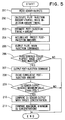
- FIGS. 5 through 7 show a second preferred embodiment of the present invention and mainly parts different from the first embodiment described above will be explained below.
- the post-injection is executed intermittently as described below, so that exhaust gas containing hydrocarbon supplied by the post-injection and exhaust gas containing no hydrocarbon alternately flow.
- the period during which the post-injection is executed is set to be longer than the period determined from the detection of the oxygen sensor 20.
- Step 201 reads each signal output from the accelerator pedal sensor 26, the engine speed sensor 27, the air flow sensor 12, the oxygen sensor 20 and the exhaust gas temperature sensor 21. Then, Step 202 calculates a pilot injection amount and its injection timing as well as a main injection amount and its injection timing from the output signals of the accelerator pedal sensor 26 and the engine speed sensor 27.
- Step 203 the process advances to Step 203 to estimate an NO x discharge from the diesel engine 10 based on the output signals of the accelerator pedal sensor 26 and the engine speed sensor 27 and to calculate a post-injection amount and its injection timing from the estimated NO x discharge and the output signal from the exhaust gas temperature sensor 21.
- Step 204 accumulates the predetermined post-injection amounts every time when the program is activated from the end of the post-injection of the last time to find the cumulative post-injection amount in order to calculate the post-injection amount corresponding to the elapsed time (crank angle) from the end of the post-injection of the last time to the present moment.
- Step 205 outputs injection commands of pilot injection and main injection sequentially to the fuel injection valve 14 of each cylinder.
- Step 206 determines whether or not the predetermined time has passed from the end of the post-injection of the last time.
- the predetermined time is a time longer than the period determined from the detection responsibility of the oxygen sensor 20 and is set within a range of 20 ms to 500 ms or more (preferably within a range of 50 ms to 200 ms), for example.
- the present program is finished without executing the processes thereafter.
- Step 207 When the predetermined time has passed since the end of the post-injection of the last time, the process advances to Step 207 to output a post-injection command to the fuel injection valve 14 of the appropriate cylinder and the post-injection is executed in the expansion or exhaust stroke of the cylinder.
- Step 208 clear the cumulative post-injection amount to zero and to determine whether or not the output signal of the oxygen sensor 20 has reached the maximum value within the above-mentioned predetermined time and has stabilized temporarily in Step 209. That is, it is determined whether or not the oxygen sensor 20 has been able to detect the concentration of oxygen within the exhaust gas containing no unburned hydrocarbon supplied by the post-injection (concentration of oxygen when no post-injection is executed).
- Step 209 is "No"
- the output signal of the oxygen sensor 20 has been influenced by the post-injection and the concentration of oxygen necessary for controlling the EGR (concentration of oxygen within the EGR gas) cannot be detected accurately, so that the present program is finished without executing the processes thereafter.
- Step 210 compares the output signal of the oxygen sensor 20 with the target concentration of oxygen to increment or decrement the EGR gas flow rate by controlling the power fed to the EGR control valve 24 in correspondence with the result of the comparison. Thereby, the EGR may be controlled accurately and the rate of purification of NO x by the EGR may be enhanced.
- Step 211 compares the maximum value (i.e., the concentration of oxygen in the exhaust gas containing no hydrocarbon supplied by the post-injection) with the minimum value (i.e., the concentration of oxygen in the exhaust gas containing hydrocarbon supplied by the post-injection) within the above-mentioned predetermined time in the output signal of the oxygen sensor 20 to calculate the variation of the output of the oxygen sensor 20 within the predetermined time and to calculate an amount of hydrocarbon post-injected based on the variation.
- the command value of the post-injection is incremented or decremented.
- the calculation of the variation of the output of the oxygen sensor 20 within the predetermined time may be executed also by integrating (accumulating) the difference between the output of the oxygen sensor 20 and the concentration of oxygen when no post-injection is executed within the predetermined time in Step 211.
- the variation of the output of the oxygen sensor 20 in which the state of change in the middle of the output of the oxygen sensor 20 is also taken into consideration may be found.
- the change of the output of the oxygen sensor 20 is induced by the fact that the exhaust gas containing hydrocarbon supplied by the post-injection and the exhaust gas containing no hydrocarbon flow alternately, it is possible to estimate the amount of hydrocarbon post-injected from the variation of the output of the oxygen sensor 20 within the predetermined time. Accordingly, the deviation of the post-injection amount caused by the difference of individual signals (variation) and the elapsed deterioration of the fuel injection valve 14 and the error of the control system may be corrected and hydrocarbon may be supplied always in proper quantities stably to the NO x catalyst 19, thus contributing to the improvement of the rate of purification of NO x , by correcting the amount of post-injected hydrocarbon based on the variation of the output of the oxygen sensor 20.
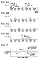
- FIGS. 6A-6D are graphs showing fuel injection waveforms of cylinders (1) through (4) when the engine control program shown in FIG. 5 is executed during steady-state operation. While the pilot injection and main injection are executed in the same manner in all of cylinders (1) through (4), the post-injection is not executed in cylinders (2) and (3) because it is not executed until the predetermined time which is longer than the period determined from the detection responsibility of the oxygen sensor 20 elapses since it has been executed in cylinder (1). It is then executed in cylinder (4) after the elapse of the predetermined time. Because post-injection is not executed again until the predetermined time elapses since it has been executed in cylinder (4), it is not executed in cylinders (1) and (2). It is executed in cylinder (4) when the predetermined time elapses and the same process is repeated thereafter.
- FIG. 7 is a graph showing a waveform of the output signal of the oxygen sensor 20 when the post-injection shown in the above-mentioned graphs in FIGS. 6A-6D is executed.
- the output signal of the oxygen sensor 20 drops every time post-injection is executed in cylinder (1), cylinder (4) and cylinder (3) as shown in FIG. 7.
- the period of fluctuation of the output corresponds to 540° CA. Because the exhaust gas containing no unburned hydrocarbon supplied by the post-injection is discharged from the two cylinders and flows into the oxygen sensor 20 to be replaced within the oxygen sensor 20 since the time the post-injection has been executed until the next post-injection is executed, the output of the oxygen sensor 20 increases.
- the output of the oxygen sensor 20 reaches the maximum value (i.e., the concentration of oxygen within the exhaust gas when no post-injection is executed) after the predetermined time which is determined from the detection responsibility of the oxygen sensor 20 and the concentration of oxygen necessary for controlling the EGR (the concentration of oxygen within the EGR gas) may be detected accurately without being influenced by the post-injection by detecting the maximum value.
- the maximum value i.e., the concentration of oxygen within the exhaust gas when no post-injection is executed
- the concentration of oxygen necessary for controlling the EGR may be detected accurately without being influenced by the post-injection by setting the period during which the post-injection is executed to be longer than the period determined from the detection responsibility of the oxygen sensor 20 in the second embodiment described above, the output signal of the oxygen sensor 20 need not be corrected, thus differing from the first embodiment described above. That is, the EGR may be controlled accurately and the rate of purification of NO x by the EGR may be enhanced without correcting the output signal of the oxygen sensor 20, i.e., by using it in controlling the EGR as it is. Thereby, it becomes possible to purify NO x efficiently by effectively exhibiting the both functions of the NO x catalyst 19 and the EGR.
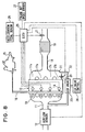
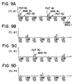
- the post-injection is executed only in a specific cylinder (cylinder (1) in the present case) in a third preferred embodiment of the present invention shown in FIGS. 8 and 9A-9D. That is, the post-injection amount of all the cylinders is injected only in the specific cylinder (1).
- the position where the oxygen sensor 20 is set and the position of a connection port 31 of the EGR pipe 22 (exhaust gas recirculating passage) on the exhaust pipe side That is, the oxygen sensor 20 is disposed in the exhaust manifold 17d of cylinder (4) at the position distant farthest from the specific cylinder (1) in which the post-injection is executed in the third embodiment.
- the connection port 31 of the EGR pipe 22 on the exhaust pipe side is connected to the exhaust manifold 17d of cylinder (4) at the position most distant from the specific cylinder (1) in which the post-injection is executed.
- FIGS. 9A-9D are graphs showing fuel injection waveforms of cylinders (1) through (4) in the third embodiment.
- pilot injection and main injection are executed in the same manner to all cylinders
- post-injection is executed only in the specific cylinder (1).
- the exhaust gas containing hydrocarbon supplied by the post-injection flows only to the exhaust manifold 17a of the specific cylinder (1) and the exhaust gas containing no hydrocarbon supplied by the post-injection flows to the exhaust manifolds 17b, 17c and 17d of the other cylinders (2), (3) and (4).
- the concentration of oxygen may be detected relatively accurately without being influenced by hydrocarbon supplied by post-injection by disposing the oxygen sensor 20 at the exhaust manifold 17d of the cylinder (4).
- the concentration of oxygen within the exhaust gas may be detected relatively accurately without correcting the output value of the oxygen sensor 20 like the first embodiment described above.
- the EGR pipe 22 is connected to the exhaust manifold 17d of the cylinder (4) at the position distant most from the specific cylinder (1) in which post-injection is executed, so that the exhaust gas containing hydrocarbon supplied by post-injection is hardly returned to the induction system via the EGR pipe 22 even when post-injection is executed in the cylinder (1), the supply of hydrocarbon by the EGR may be suppressed from reducing and the rate of purification of NO x of the NO x catalyst 19 may be prevented from dropping. Thereby, it becomes possible to purify NO x efficiently while exhibiting both functions of the NO x catalyst 19 and the EGR effectively.
- FIG. 10 shows rates of hydrocarbon recirculated to the induction side by the EGR among the amount of hydrocarbon post-injected when the cylinders in which the post-injection is executed are changed sequentially from (1) to (4) when the rate of EGR is 30%.
- the rate of recirculation to the induction side is the highest when the post-injection is executed in the cylinder (4) which is closest to the EGR pipe 22 and the rate of recirculation to the induction side is the lowest when the post-injection is executed in the cylinder (1) which is most distant from the EGR pipe 22.
- oxygen sensor 20 is positioned at the upstream side of the connection port of the EGR pipe 22 at the exhaust pipe side in the example shown in FIG. 9; however, this order may be reversed.
- the specific cylinder in which the post-injection is executed has been only one cylinder in the third embodiment, it may be two or more cylinders. It is also possible in this case to set the position of the oxygen sensor 20 and that of the connection port 31 of the EGR pipe 22 on the exhaust pipe side in the exhaust manifold of the cylinder distant most from the specific cylinders in which the post-injection is executed.
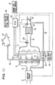
- FIG. 11 shows a fourth preferred embodiment of the present invention.
- This embodiment is different from the structure shown in FIG. 1 in that the connection port 32 of the EGR pipe 22 on the exhaust pipe side is connected to the downstream side of the NO x catalyst 19 and that an exhaust throttle valve 33 is on the downstream side of the connection port 32 of the EGR pipe 22 on the exhaust pipe side.
- all of the exhaust gas containing unburned hydrocarbon supplied by post-injection flows into the NO x catalyst 19 to be used for the reduction and purification of NO x , and part of the exhaust gas containing no unburned hydrocarbon or containing unburned hydrocarbon a little which has passed through the NO x catalyst 19 is returned to the intake pipe 11 as the EGR gas. Accordingly, even when EGR is executed, the supply of hydrocarbon to the NO x catalyst 19 by post-injection is not reduced at all and it becomes possible to purify NO x efficiently by effectively exhibiting both functions of the NO x catalyst 19 and the EGR.
- the exhaust pressure at the downstream side of the NO x catalyst 19 is low compared to that of the upstream side, there is a case where the EGR gas flow rate cannot be obtained fully. Then, the exhaust pressure at the connection port 32 of the EGR pipe 22 is boosted to maintain enough EGR gas flow by providing the exhaust throttle valve 33 at the downstream side of the connection port 32 of the EGR pipe 22 on the exhaust pipe side and by throttling the aperture of the exhaust throttle valve 33 only when the EGR is controlled in the fourth embodiment.
- FIG. 12 shows a fifth preferred embodiment of the present invention whose structure is different from the structure shown in FIG. 1 in that an NO x catalyst for EGR gas 34 for reducing and purifying NO x within the EGR gas is in the EGR pipe 22.
- an NO x catalyst for EGR gas 34 for reducing and purifying NO x within the EGR gas is in the EGR pipe 22.
- hydrocarbon within the EGR gas reacts with NO x and the NO x is reduced and purified by the catalytic action of the NO x catalyst for EGR gas 34 in the process when the part of the exhaust gas containing the post-injected hydrocarbon flows through the EGR pipe 22 as the EGR gas and passes through the NO x catalyst 34 for EGR gas.
- NO x within the EGR gas which is returned to the diesel engine 10 is reduced, NO x is reduced efficiently by the EGR, and NO x emitted from the diesel engine 10 is reduced.
- the NO x catalyst for EGR gas 34 may be disposed on the upstream/downstream side of the EGR valve 23 as long as it is disposed in the middle of the EGR pipe 22.
- FIGS. 13 through 15E A sixth embodiment in which the present invention is applied to a four-cylinder diesel engine, for example, will be explained below based on FIGS. 13 through 15E.
- the structure of this embodiment is different from that of the first embodiment in that the EGR passage 22, EGR valve 23, and EGR controller 24 are omitted.
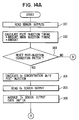
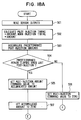
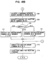
- the injection control program executed by the ECU 25 in this embodiment will be explained below based on the flowchart shown in FIGS. 14A and 14B.
- the injection control program is executed repeatedly every predetermined time or every predetermined crank angle.
- Step 302 calculates a pilot injection amount and its injection timing as well as a main injection amount and its injection timing from the output signals of the accelerator pedal sensor 26 and the engine speed sensor 27. Further, it estimates an NO x discharge amount from the diesel engine 10 based on the output signals of the accelerator pedal sensor 26 and the engine speed sensor 27 and calculates command values of a post-injection amount and its injection timing from the estimated NO x discharge and the output signal from the exhaust gas temperature sensor 21. It is noted that post-injection is executed when the temperature of the NO x catalyst 19 is determined to be within a predetermined activated temperature range based on the output signal of the exhaust gas temperature sensor 21.
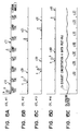
- FIGS. 15A-15E are graphs showing fuel injection waveforms of the fuel injection valve 14 of each cylinder based on a fuel injection signal from the ECU 25.
- Reference letter (a) within FIGS. 15A-15E denotes pilot injection, reference letter (b) main injection and reference letters (c10 through c41) post-injection.
- Main injection is executed near the compression top dead center to generate engine output for each cylinder.
- pilot injection is executed to inject a small amount of fuel. When this fuel is ignited, main injection is executed to reduce the pre-mixed combustion at the beginning of the combustion to reduce the NO x discharge.
- Post-injection is executed in the expansion or exhaust stroke after combustion. Accordingly, the post-injected fuel is mixed with the exhaust gas while in the unburned state and is discharged from the diesel engine 10. It is then supplied to the NO x catalyst 19 to be consumed for the reduction and purification of NO x . Post-injection is executed in all of the cylinders for the fuel injection in the sixth embodiment.
- Step 310 When it is determined not to be necessary to set the correction factor k(i) again in Step 303 described above, the process advances to Step 310.
- Step 304 When it is determined to be necessary to set it again, the process advances to Step 304 to calculate the concentration of oxygen within the exhaust gas when no post-injection is executed from map data or the like found by experiments and simulation in advance based on the output signals of the accelerator pedal sensor 26 and the engine speed sensor 27.
- the exhaust gas flow rate is calculated from the output signal of the air flow sensor 12
- an amount of HC (hydrocarbon) is calculated from the post-injection amount command value
- the concentration of HC within the exhaust gas is calculated from the exhaust gas flow rate
- the amount of HC and the concentration of oxygen A within the exhaust gas when post-injection is executed is calculated by subtracting the concentration of oxygen necessary for burning the concentration of HC within the exhaust gas from the concentration of oxygen within the exhaust gas described above when the post-injection is not executed.
- Step 305 reads the output signal of the oxygen sensor 20.
- Step 306 then averages the output signal of the oxygen sensor 20 over 180° CA to find an average concentration of oxygen B.
- the concentration of oxygen is averaged to improve the accuracy of detecting the concentration of oxygen by averaging by the output period of the post-injection command because the output signal of the oxygen sensor 20 fluctuates with that period.
- Step 307 in FIG. 14B compares the average concentration of oxygen B calculated in Step 306 and the concentration of oxygen in exhaust gas A when the post-injection is executed calculated in Step 304.
- B > A it is determined that the actual HC supply (post-injection amount) is less than the amount of HC to be supplied by the post-injection (command value).
- Step 310 the process advances to Step 310 also when it is determined in Step 303 described above that the correction factor k(i) of the post-injection amount command value need not be set again.
- Step 311 then outputs commands (injection amount and injection timing) of the pilot injection, main injection and post-injection to the fuel injection valve 14.
- FIGS. 15A-15E are graphs showing fuel injection waveforms of the first through fourth cylinders (1) through (4) and FIG. 15E is a waveform of an output signal of the oxygen sensor 20 during steady-state operation.
- the solid line indicates an actual sensor output and the broken line indicates the concentration of oxygen in exhaust gas A when post-injection is executed calculated in Step 304.
- the exhaust gas flows into the oxygen sensor 20 in the exhaust stroke so that a phase (time) delays and the output of the oxygen sensor 20 changes.
- the output of the oxygen sensor 20 in the exhaust gas (c10) corresponding to cylinder (1) is averaged by the crank angle of 180°, it becomes equal to the concentration of oxygen in exhaust gas A indicated by the broken line. That is, because the amount of post-injection c10 executed in the cylinder (1) coincides with the target amount of post-injection (command value), the correction factor k(i) of the post-injection amount command value is not set again. Accordingly, the amount of the next post-injection c11 of cylinder (1) is equal to that of c10.
- the output of the oxygen sensor 20 of the exhaust gas from each cylinder becomes equal to the concentration of oxygen in the exhaust gas A indicated by the broken line when it is averaged by the crank angle of 180°.
- the proper amount of hydrocarbon may be always supplied to the catalyst, the rate of purification of NO x may be improved and the post-injected unburned hydrocarbon may be prevented from being emitted, thus meeting with the needs of low emission, by correcting the command value of the post-injection amount by the actual post-injection amount detected by the oxygen sensor 20.
- the output of the oxygen sensor 20 has been averaged over 180° CA in tee sixth embodiment, it may be averaged over 360° CA or 720° CA, for example.
- the concentration of HC within the exhaust gas may be calculated by calculating the exhaust gas flow rate by the output signal of the air flow sensor 12 and the rate of EGR determined from the engine running state in Step 304.
- the exhaust gas flow rate may be calculated from the engine speed.
- the concentration of oxygen in exhaust gas when no post-injection is executed has been calculated by using the map data from the output signals of the accelerator pedal sensor 26 and the engine speed sensor 27 in Step 304 in FIG. 14A in the sixth embodiment
- the concentration of oxygen in exhaust gas when no post-injection is executed is actually measured by the oxygen sensor 20 by stopping the post-injection for a predetermined time in the seventh embodiment shown in FIGS. 16A through 17E.
- the system structure of the seventh embodiment is the same as the structure shown in FIG. 13 and explained in connection with the sixth embodiment.
- Steps 401 through 403 are the same as those in Steps 301 through 303 shown in FIG. 14A.
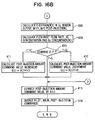
- Step 404 reads the output of the oxygen sensor 20 when post-injection is executed and then Step 405 temporarily sets the post-injection amount command value of all the cylinders to zero to stop the post-injection of all the cylinders.
- Step 406 determines whether or not the "predetermined time” has passed since the post-injection had been stopped.
- the "predetermined time” is set to a time longer than the period determined from the responsiveness of the oxygen sensor 20, e.g., 0.2 s to 0.5 s.
- Step 406 determines that the predetermined time has not passed yet, the process advances to Step 413 in FIG. 16B described below.
- Step 407 reads the output of the oxygen sensor 20 when no post-injection is executed (i.e., while the post-injection is stopped) to detect the concentration of oxygen in exhaust gas when no post-injection is executed.
- Step 408 in FIG. 16B calculates the difference between the output C of the oxygen sensor 20 when post-injection is executed read in Step 404 and the output D of the oxygen sensor 20 when no post-injection is executed read in Step 407 (i.e., actual variation of concentration of oxygen supplied by the post-injection).
- Step 409 calculates the exhaust gas flow rate from the output signal of the air flow sensor 12 to calculate an amount of HC corresponding to the post-injection amount command value, to calculate the concentration of HC within the exhaust gas from the exhaust gas flow rate and the amount of HC and to calculate the concentration of oxygen F necessary for burning the concentration of HC within the exhaust gas (i.e., the variation of the concentration of oxygen estimated from the post-injection amount command value).
- Step 410 compares the difference E between the output C of the oxygen sensor 20 when the post-injection is executed read in Step 408 and the output D of the oxygen sensor 20 when no post-injection is executed with the concentration of oxygen F necessary for burning the concentration of HC within the exhaust gas calculated in Step 409.
- F > E it is determined that the actual supply of HC is less than the amount of HC to be supplied by the post-injection (commanded value).
- FIGS. 17A-17E are graphs showing fuel injection waveforms of first through fourth cylinders (1) through (4) and FIG. 17E shows an output signal wave of the oxygen sensor 20 during steady-state operation.
- Reference letter (a) in FIGS. 17A-17D denotes pilot injection
- reference letter (b) the main injection and reference letters (c10 through c42) the post-injection.
- the solid line indicates an actual output of the sensor
- the broken line indicates the concentration of oxygen in exhaust gas when no post-injection is executed
- the alternate chain line indicates the concentration of oxygen in exhaust gas estimated from the post-injection command value.
- the post-injections (c10 through c40) are executed sequentially from cylinder (1) to cylinder (4) and the concentration of oxygen C of the exhaust gas emitted from each cylinder at that time is detected. Then, the post-injections (c11 through c41) of all cylinders (1) through (4) are set to zero, so that the output of the oxygen sensor 20 gradually reaches the concentration of oxygen D when no post-injection is executed.
- the variation E of the concentration of oxygen caused by the post-injection executed for each cylinder is calculated from the difference between the detected concentration of oxygen D when no post-injection is executed and the concentration of oxygen C of the exhaust gas emitted from each cylinder. After that, the variation F of the concentration of oxygen estimated from the post-injection amount command value is compared with the actual variation E of the concentration of oxygen caused by the post-injection executed for each cylinder to correct the post-injection amount command value.
- the correction factor k(i) of the post-injection amount command value is not set again. Accordingly, the amount of the post-injection c12 of the cylinder (1) at the time immediately after the next is equal to that of c10. Next, because the amount of the post-injection c20 executed in cylinder (2) is less than the target amount of post-injection, the correction factor k(2) of the post-injection amount command value is multiplied by a coefficient of increment k3 to be set again.
- the amount of post-injection c22 of cylinder (2) at the time immediately after the next is incremented more than that of c20.
- the correction factor k(3) of the post-injection amount command value is set again by multiplying by a coefficient of decrement k4. Accordingly, the amount of post-injection c32 of cylinder (3) at the time immediately after the next is decremented to be less than that of c30.
- the correction factor k(4) of the post-injection amount command value is not set again. Accordingly, the amount of post-injection c42 of cylinder (4) at the time immediately after the next is equal to that of c40. Because the amount of post-injection (c12 through c42) of each cylinder in the cycle immediately after the next is corrected by the above-mentioned processing, the output of the oxygen sensor 20 for detecting the exhaust gas emitted from each cylinder is equalized.
- the exhaust gas containing no hydrocarbon supplied by the post-injection flows through the oxygen sensor 20 during the specific period in which the post-injection is stopped to all the cylinders. Accordingly, while the oxygen sensor 20 normally detects the concentration of oxygen of the exhaust gas after burning the hydrocarbon supplied by the post-injection at the oxygen sensor 20, it can directly detect the concentration of oxygen within the exhaust gas containing no hydrocarbon supplied by post-injection. Thereby, the amount of post-injection may be estimated accurately based on the variation of the output of the oxygen sensor 20 before and after post-injection is stopped, and the command value of the post-injection amount may be corrected accurately.
- the correction factor of the post-injection amount command value has been set again per cylinder in the seventh embodiment, the correction factor may be set again to the average value of the post-injection amount of all the cylinders.
- the post-injection of all the cylinders has been stopped forcibly only for the specific period only when the correction factor k(i) of the post-injection amount command value is set again to measure the concentration of oxygen of the emission when no post-injection is executed
- the post-injection is always executed for a time interval longer than the period determined from the oxygen sensor 20 to measure the concentration of oxygen of emission when no post-injection is executed in an eighth embodiment shown in FIGS. 18A through 19E.
- the system structure of this embodiment is the same as the structure explained in the sixth embodiment and shown in FIG. 13.
- Step 501 each signal output from the accelerator pedal sensor 26, the engine speed sensor 27, the air flow sensor 12 and the exhaust gas temperature sensor 21 are read to detect the operational state of the diesel engine 10 and correction factors k of the post-injection amount of all the cylinders stored in the RAM (not shown) of the ECU 25 are read.
- Step 502 then calculates command values of a pilot injection amount and its injection timing, command values of a main injection amount and its injection timing and command values of post-injection and its injection timing by the same processing with that in Step 302 in FIG. 14A.
- Step 504 determines whether or not a "predetermined time” has passed since the post-injection of the last time.
- the "predetermined time” is a time determined from the detection responsiveness of the oxygen sensor 20 and is set within a range of 20 ms to 500 ms or more preferably, 50 ms to 200 ms, for example.
- Step 504 When the "predetermined time" has not passed since the post-injection of the last time, the process advances from Step 504 to Step 506 to set the post-injection amount command value to zero and advances to Step 513 (i.e., without executing post-injection).
- Step 507 sets the post-injection amount to zero and Step 508 in FIG. 18B calculates the difference G between the average value and the maximum value of the oxygen sensor 20 output within the predetermined time.
- the post-injection amount command values are averaged within the predetermined time to calculate the concentration of oxygen H to be changed in Step 509.
- Step 510 compares the difference G between the average value and the maximum value of the oxygen sensor 20 within the predetermined time calculated in Step 508 with the concentration of oxygen H to be changed by the average value of the post-injection amount command value within the predetermined time calculated in Step 509.
- H > G it is determined that the actual supply of HC is less than the amount of HC to be supplied by post-injection (commanded value).
- Step 514 then outputs commands (injection amount and injection timing) of pilot injection, main injection and post-injection to the fuel injection valve 14.
- FIGS. 19A-19E are graphs showing fuel injection waveforms of first through fourth cylinders (1) through (4) and FIG. 19E is a graph of a waveform of an output signal of the oxygen sensor 20 during steady-state operation.
- Reference letter (a) in FIGS. 19A-19E denotes pilot injection, reference letter (b) main injection and reference letter (c10 through c31) post-injection.
- a solid line indicates an actual sensor output and a broken line indicates the concentration of oxygen in exhaust gas when no post-injection is executed.
- the pilot injection and main injection are executed in the same manner in all of cylinders (1) through (4), post-injection is not executed until the predetermined time which is determined from the detection responsiveness of the oxygen sensor 20 passes since when the post-injection is executed in cylinder (1) (c10), so that no post-injection is executed in cylinder (2) (c20) and cylinder (3) (c30) and post-injection is executed in cylinder (4) (c40) when the predetermined time has passed. Because post-injection is not executed until the predetermined time passes after being executed in cylinder (4), it is not executed in cylinder (1) (c11) and cylinder (2) (c21) and is executed in cylinder (3) (c31) when the predetermined time has passed. Similar processing is repeated thereafter.
- the output signal of the oxygen sensor 20 drops every time post-injection is executed in cylinder (1), cylinder (4) and cylinder (3) and the fluctuation period of the output corresponds to 540° CA under this injection control.
- the exhaust gas containing no unburned hydrocarbon supplied by post-injection is emitted from the two cylinders and flows into the oxygen sensor 20 to be gas-exchanged within the oxygen sensor 20 until the next post-injection is executed since the post-injection has been executed, so that the output of the oxygen sensor 20 increases.
- the output of the oxygen sensor 20 is maximized after the predetermined time determined from the detection responsiveness of the oxygen sensor 20 and the concentration of oxygen in exhaust gas while no post-injection is executed may be detected accurately by detecting the maximum value. It also allows the correction factor k of the post-injection amount command value to be set again and the post-injection command to be corrected accurately.
- the correction factor k(i) may be set again for every cylinder.
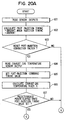
- an exhaust gas temperature sensor on the upstream side of the NO x catalyst 19 is used as the sensor for detecting the information reflecting the post-injection amount to correct the command value of the post-injection amount based on the variation of the exhaust gas temperature corresponding to the amount of post-injection burned within the cylinders in the ninth embodiment shown in FIGS. 20A through 21E.
- the system structure of the ninth embodiment is the same as the structure of the sixth embodiment and shown in FIG. 13 except that element 20 is an exhaust gas temperature sensor, rather than the oxygen sensor 20 (hereinafter, although not specifically shown in the drawings, the exhaust gas temperature sensor will be denoted by the reference numeral 20').
- Steps 601 through 603 are the same with those in Steps 301 through 303 shown in FIG. 15A described above.
- Step 604 reads the output of the exhaust gas temperature sensor 20' when post-injection is executed at the normal post-injection timing (emission temperature at the normal post-injection timing).
- Step 605 advances and sets the post-injection timing command value to a predetermined value and then to calculate a temperature rise of the exhaust gas R from the quantity of heat of combustion of the post-injection amount command value in Step 606.
- Step 607 determines whether or not a "predetermined time” has passed since the post-injection timing command value has been advanced and set.
- the "predetermined time” is a time determined from the responsiveness of the exhaust gas temperature sensor 20' and is set within a range from 2 s to 10 s, for example.
- the process advances to Step 614 in FIG. 20B described below.
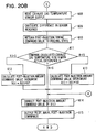
- step 608 in FIG. 20B reads the output of the exhaust gas temperature sensor 20' when the post-injection timing command value has been advanced and set (the exhaust gas temperature when the post-injection timing has been advanced).
- Step 609 calculates the difference S between the output of the exhaust gas temperature sensor 20' at the normal post-injection timing read in Step 604 and the output of the exhaust gas temperature sensor 20' when the post-injection timing has been advanced read in Step 608 (actually measured temperature rise of the exhaust gas)
- Step 610 returns the post-injection timing command value to the original state before the advancement.
- Step 611 compares the temperature rise of the exhaust gas R calculated from the quantity of heat of combustion of the post-injection amount command value in Step 606 with the difference S (actually measured temperature rise of the exhaust gas) of the outputs of the exhaust gas temperature sensor 20' calculated in Step 609.
- Step 614 the process advances to Step 614 also when the determination result is determined to be "NO" either in Step 603 or Step 607 described above.
- Step 615 then outputs commands (injection amount and injection timing) of pilot injection, main injection and post-injection to the fuel injection valve 14.
- FIGS. 21A-21E are graphs showing fuel injection waveforms of first through fourth cylinders (1) through (4) and FIG. 21E is a waveform of an output signal of the exhaust gas temperature sensor 20' during steady-state operation.
- Reference letter (a) in FIGS. 21A-21E denotes pilot injection, reference letter (b) main injection and reference letters (c10 through c42) post-injection.
- post-injections c10 through c40 are executed in cylinders (1) through (4) at the normal injection timing and the temperature of the exhaust gas emitted from each cylinder at that time is detected.
- the timing of post-injections from cylinder (1) to cylinder (4) (c11 to c41) is advanced and set and the post-injected fuel burns within the cylinders so that the exhaust gas temperature rises gradually and thus, the output of the exhaust gas temperature sensor 20' gradually rises.
- the variation of the exhaust gas temperature S caused by the combustion of post-injection within the cylinder for each cylinder is calculated from the difference S between the detected output of the exhaust gas temperature sensor 20' when the post-injection timing has been advanced and the output of the exhaust gas temperature sensor 20' at the normal post-injection timing.
- This variation S of the exhaust gas temperature is compared with the temperature rise of the exhaust gas R calculated from the post-injection amount command value to correct the post-injection amount command value.
- the timing of the post-injections from cylinder (1) to cylinder (4) (c12 to c42) is returned to the original state before the advancement and the post-injection amount command value is corrected to be output to the fuel injection valve 14.
- the fourth embodiment described above allows the post-injection amount to be estimated accurately from the variation of the output of the exhaust gas temperature sensor 20' before and after the advancement of the post-injection timing and the command value of the post-injection amount to be corrected accurately by advancing the post-injection timing more than the normal timing only by the specific period to burn the post-injection fuel within the cylinder.
- the correction factor of the post-injection amount command value has been set again per cylinder in the ninth embodiment, the correction factor may be set again to the average value of the post-injection amounts of all the cylinders.
- the number of cylinders is not limited to four and may be a different number.
- the internal combustion engine to which the present invention can be applied is not limited only to a diesel engine and it may be applied to an intra-cylinder injection (direct injection) type gasoline engine as well.
- the EGR gas flow rate has been corrected based on the output signal (or its corrected value) of the oxygen sensor 20 in all of the embodiments described above; however, it is possible to arrange the system to correct the fuel injection amount or the intake air amount.
- the intake air amount may be corrected by controlling the aperture of the throttle valve in the intake pipe 11.
- the oxygen sensor 20 or the exhaust gas temperature sensor 20' has been used as the sensor for detecting the information reflecting the post-injection amount in each of the embodiments described above, the sensor of the present invention is not limited to those.
- a HC sensor for detecting the concentration of hydrocarbon within the exhaust gas or a sensor for detecting a lift of a needle value of the fuel injection valve 14 may be used.
Landscapes
- Engineering & Computer Science (AREA)
- Chemical & Material Sciences (AREA)
- Combustion & Propulsion (AREA)
- General Engineering & Computer Science (AREA)
- Mechanical Engineering (AREA)
- Chemical Kinetics & Catalysis (AREA)
- Health & Medical Sciences (AREA)
- Toxicology (AREA)
- Biomedical Technology (AREA)
- Environmental & Geological Engineering (AREA)
- Analytical Chemistry (AREA)
- General Chemical & Material Sciences (AREA)
- Oil, Petroleum & Natural Gas (AREA)
- Exhaust Gas After Treatment (AREA)
- Electrical Control Of Air Or Fuel Supplied To Internal-Combustion Engine (AREA)
Abstract
Description
Claims (26)
- An exhaust emission control system for an internal combustion engine (10), the system comprising:control means (25) for controlling operation of the engine (10) based on control variables;a plurality of fuel injecting means (14), each being for injecting fuel into a corresponding cylinder of the engine (10);a catalyst (19), in an exhaust passage (18) of the engine (10), for reducing and purifying nitrogen oxides within exhaust gas from the engine (10);an oxygen sensor (20), in the exhaust passage (18), for detecting a concentration of oxygen within the exhaust gas;operational state detecting means (12, 26, 27) for detecting an operational state of the engine (10);injection control means (25) for outputting a main injection command for generating engine output to the plurality of fuel injecting means (14) and for outputting a post-injection command, for supplying hydrocarbon to the catalyst (19), to the fuel injecting means (14) of at least one cylinder based on the detected operational state;oxygen sensor correcting means (25) for correcting an output of the oxygen sensor (20) based on the post-injection command; andengine control variable correcting means (25) for correcting the control variables to enhance a rate of purification of nitrogen oxides based on the output of the oxygen sensor (20) corrected by the oxygen sensor correcting means (25).
- The system of claim 1, wherein the oxygen sensor correcting means (25) comprises:exhaust gas flow rate estimating means (25) for estimating a flow rate of exhaust gas based on the detected operational state; andhydrocarbon concentration estimating means (25) for estimating a concentration of hydrocarbon within exhaust gas around the oxygen sensor (20) based on the estimated flow rate of exhaust gas and the post-injection command, and for correcting the output of the oxygen sensor (20) based on the estimated hydrocarbon concentration.
- The system of claim 2, wherein:the oxygen sensor correcting means (25) includes means for calculating a delay time until the exhaust gas reaches the oxygen sensor (20) based on the detected operational state; andthe hydrocarbon concentration estimating means is for estimating the concentration of hydrocarbon within the exhaust gas around the oxygen sensor (20) at a given moment based on the flow rate of exhaust gas before the delay time and the post-injection command.
- An exhaust emission control system for an internal combustion engine (10), the system comprising:control means (25) for controlling operation of the engine (10) based on control variables;a plurality of fuel injecting means (14), each being for injecting fuel into a corresponding cylinder of the engine (10);a catalyst (19), in an exhaust passage (18) of the engine (10), for reducing and purifying nitrogen oxides within exhaust gas from the engine (10);operational state detecting means (12, 26, 27) for detecting an operational state of the engine (10);injection control means (25) for outputting a main injection command for generating engine output to the plurality of fuel injecting means (14) and for outputting a post-injection command, for supplying hydrocarbon to the catalyst (19), to the fuel injecting means (14) of at least one cylinder based on the detected operational state;an oxygen sensor (20), in the exhaust passage (18), for detecting a concentration of oxygen within the exhaust gas; andengine control variable correcting means (25) for correcting the control variables to enhance a rate of purification of nitrogen oxides based on an output of the oxygen sensor (20);
wherein the injection control means (25) is for outputting the post-injection command in a period longer than a period based on the detection responsiveness of the oxygen sensor (20). - The system of claim 4, wherein the injection control means (25) is for correcting the post-injection command and outputting it to the fuel injecting means (14) of at least one cylinder based on a variation of the output of the oxygen sensor (20) within a predetermined time which is longer than a period based on the detection responsiveness of the oxygen sensor (20).
- An exhaust emission control system for an internal combustion engine (10), the system comprising:control means (25) for controlling operation of the engine (10) based on control variables;a plurality of fuel injecting means (14), each being for injecting fuel into a corresponding cylinder of the engine (10);a catalyst (19), in an exhaust passage (18) of the engine (10), for reducing and purifying nitrogen oxides within exhaust gas from the engine (10);operational state detecting means (12, 26, 27) for detecting an operational state of the engine (10);injection control means (25) for outputting a main injection command for generating engine output to the plurality of fuel injecting means (14) of each cylinder and for outputting a post-injection command, for supplying hydrocarbon to the catalyst (19), to the fuel injecting means (14) of a specific cylinder based on the detected operational state;an oxygen sensor (20), in the exhaust passage (18), for detecting a concentration of oxygen within the exhaust gas; andengine control variable correcting means (25) for correcting the control variables to enhance a rate of purification of nitrogen oxides based on an output of the oxygen sensor (20);
wherein the oxygen sensor (20) is disposed in an exhaust manifold (17) of a cylinder of the engine (10) at a position most distant from the specific cylinder in which the post-injection is executed. - The system of one of claims 1 through 6, further comprising an exhaust gas recirculating passage (22), for recirculating part of the exhaust gas to an induction system (11) of the engine (10), connected to an exhaust manifold (17) of a cylinder at a position most distant from the specific cylinder in which the post-injection is executed.
- The system of one of claims 1 through 6, further comprising an exhaust gas recirculating passage (22), for recirculating part of the exhaust gas to an induction system (11) of the engine (10), connected to the exhaust passage (18) on a downstream side of the catalyst (19).
- An exhaust emission control system for an internal combustion engine (10), the system comprising:control means (25) for controlling operation of the engine (10) based on control variables;a plurality of fuel injecting means (14), each being for injecting fuel into a corresponding cylinder of the engine (10);a catalyst (19), in an exhaust passage (18) of the engine (10), for reducing and purifying nitrogen oxides within exhaust gas from the engine (10);operational state detecting means (12, 26, 27) for detecting an operational state of the engine (10);injection control means (25) for outputting a main injection command for generating engine output to the plurality of fuel injecting means (14) and for outputting a post-injection command for supplying hydrocarbon to the catalyst (19) to the fuel injecting means (14) of at least one cylinder based on the detected operational state;an oxygen sensor (20), in the exhaust passage (18), for detecting a concentration of oxygen within the exhaust gas;engine control variable correcting means (25) for correcting the control variables to enhance a rate of purification of nitrogen oxides based on an output of the oxygen sensor (20);an exhaust gas recirculating passage (22) for recirculating part of the exhaust gas to an induction system (11) of the engine (10); anda catalyst (34) for recirculated exhaust gas, in the exhaust gas recirculating passage (22), for reducing and purifying nitrogen oxides within the recirculated exhaust gas.
- A method of reducing and purifying nitrogen oxides within exhaust gas emitted from an internal combustion engine (10), the method comprising:detecting an operational state of the engine (10);executing, based on the detected operational state, main injection by issuing a main injection command for generating engine output to a plurality of fuel injectors (14) of each cylinder of the engine (10) as well as executing post-injection by issuing a post-injection command, for supplying hydrocarbon to the catalyst (19), to fuel injecting means (14) of at least one cylinder;detecting a concentration of oxygen within the exhaust gas using an oxygen sensor (20); andcorrecting an output of the oxygen sensor (20) based on the post-injection command to correct control variables of the engine (10) to enhance a rate of nitrogen oxide purification based on the corrected output.
- An exhaust emission control system for an internal combustion engine (10), the system comprising:control means (25) for controlling operation of the engine (10) based on control variables;a plurality of fuel injecting means (14), each being for injecting fuel into a corresponding cylinder of the engine (10);a catalyst (19), in an exhaust passage (18) of the engine (10), for reducing and purifying nitrogen oxides within exhaust gas from the engine (10);an oxygen sensor (20), in the exhaust passage (18), for detecting a concentration of oxygen within the exhaust gas;operational state detecting means (12, 26, 27) for detecting an operational state of the engine (10);target oxygen concentration calculating means (25) for calculating a target concentration of oxygen within the exhaust gas based on the detected operational state;injection control means (25) for outputting a main injection command for generating engine output to the plurality of fuel injecting means (14) and for outputting a post-injection command for supplying hydrocarbon to the catalyst (19) to the fuel injecting means (14) of at least one cylinder based on the detected operational state;oxygen concentration correcting means (25) for correcting either an output of the oxygen sensor (20) or the target concentration of oxygen based on the post-injection command; andengine control variable correcting means (25) for correcting the control variables to enhance a rate of purification of nitrogen oxides based on at least one of the output of the oxygen sensor (20) after being corrected by the oxygen concentration correcting means (25), and the target oxygen concentration.
- The system of claim 11, wherein:the oxygen concentration correcting means (25) includes exhaust gas flow rate estimating means (25) for estimating the flow rate of exhaust gas based on the detected operational state; andhydrocarbon concentration estimating means (25) for estimating the concentration of hydrocarbon within exhaust gas around the oxygen sensor (20) based on the estimated flow rate of exhaust gas and the post-injection command and corrects either the output of the oxygen sensor (20) or the target oxygen concentration based on the estimated concentration of hydrocarbon.
- The system of claim 12, wherein:the oxygen concentration correcting means (25) includes means (25) for calculating a delay time until the exhaust gas reaches the oxygen sensor (20) based on the detected operational state; andthe hydrocarbon concentration estimating means (25) is for estimating the concentration of hydrocarbon within the exhaust gas around the oxygen sensor (20) at a given moment based on the flow rate of exhaust gas before the delay time and the post-injection command.
- An exhaust emission control system for an internal combustion engine (10), the system comprising:control means (25) for controlling operation of the engine (10) based on control variables;a plurality of fuel injecting means (14), each being for injecting fuel into a corresponding cylinder of the engine (10);a catalyst (19), in an exhaust passage (18) of the engine (10), for reducing and purifying nitrogen oxides within exhaust gas;operational state detecting means (12, 26, 27) for detecting an operational state of the engine (10);target oxygen concentration calculating means (25) for calculating a target concentration of oxygen within the exhaust gas based on the detected operational state;injection control means (25) for outputting a main injection command for generating engine output to the plurality of fuel injecting means (14) and for outputting a post-injection command, for supplying hydrocarbon to the catalyst (19), to the fuel injecting means (14) of at least one cylinder based on the detected operational state;an oxygen sensor (20), in the exhaust passage (18), for detecting a concentration of oxygen within the exhaust gas; andengine control variable correcting means (25) for correcting the control variables to enhance a rate of purification of nitrogen oxides based on at least one of an output of the oxygen sensor (20) and the target oxygen concentration;
wherein the injection control means (25) is for outputting the post-injection command in a period longer than a period based on the detection responsiveness of the oxygen sensor (20). - An exhaust emission control system for an internal combustion engine (10), the system comprising:control means (25) for controlling operation of the engine (10) based on control variables;a plurality of fuel injecting means (14), each being for injecting fuel into a corresponding cylinder of the engine (10);a catalyst (19), in an exhaust passage (18) of the engine (10), for reducing and purifying nitrogen oxides within exhaust gas from the engine (10);operational state detecting means (12, 26, 27) for detecting an operational state of the engine (10);target oxygen concentration calculating means (25) for calculating a target concentration of oxygen within the exhaust gas based on the detected operational state;injection control means (25) for outputting a main injection command for generating engine output to the plurality of fuel injecting means (14) and for outputting a post-injection command for supplying hydrocarbon to the catalyst (19) to the fuel injecting means (14) of a specific cylinder based on the detected operational state;an oxygen sensor (20), in the exhaust passage (18), for detecting a concentration of oxygen within the exhaust gas; andengine control variable Correcting means (25) for correcting the control variables to enhance a rate of purification of nitrogen oxides based on at least one of the output of the oxygen sensor (20) and the target oxygen concentration;
wherein the oxygen sensor (20) is disposed in an exhaust manifold (17) of a cylinder at a position most distant from the specific cylinder in which the post-injection is executed. - An exhaust emission control system for an internal combustion engine (10), the system comprising:a plurality of fuel injecting means (14), each being for injecting fuel into a corresponding cylinder of the engine (10);a catalyst (19), in an exhaust passage (18) of the engine (10), for reducing and purifying nitrogen oxides within exhaust gas from the engine (10);operational state detecting means (12, 26, 27) for detecting an operational state of the engine (10);injection control means (25) for outputting a main injection command for generating engine output to the plurality of fuel injecting means (14) and for outputting a post-injection command, for supplying hydrocarbon to the catalyst (19), to the fuel injecting means (14) of a specific cylinder based on the detected operational state; andan exhaust gas recirculating passage (22) for recirculating part of the exhaust gas to an induction system (11) of the engine (10), the exhaust gas recirculating passage (22) being connected to an exhaust manifold (17) of a cylinder at a position most distant from the specific cylinder in which the post-injection is executed.
- An exhaust emission control system for an internal combustion engine (10), the system comprising:a plurality of fuel injecting means (14), each being for injecting fuel into a corresponding cylinder of the engine (10);a catalyst (19), in an exhaust passage (18) of the engine (10), for reducing and purifying nitrogen oxides within exhaust gas from the engine (10);operational state detecting means (12, 26, 27) for detecting an operational state of the engine (10);injection control means (25) for outputting a main injection command for generating engine output to the plurality of fuel injecting means (14) and for outputting a post-injection command, for supplying hydrocarbon to the catalyst (19), to the fuel injecting means (14) of a specific cylinder based on the detected operational state; andan exhaust gas recirculating passage (22) for recirculating part of the exhaust gas to an induction system (11) of the engine (10), the exhaust gas recirculating passage (22) being connected to the exhaust passage (18) on a downstream side of the catalyst (19).
- An exhaust emission control system for an internal combustion engine (10), the system comprising:a plurality of fuel injecting means (14), each being for injecting fuel into a corresponding cylinder of the engine (10);a catalyst (19), in an exhaust passage (18) of the engine (10), for reducing and purifying nitrogen oxides within exhaust gas from the engine (10);operational state detecting means (12, 26, 27) for detecting an operational state of the engine (10);injection control means (25) for outputting a main injection command for generating engine output to the plurality of fuel injecting means (14) and for outputting a post-injection command, for supplying hydrocarbon to the catalyst (19), to the fuel injecting means (14) of at least one cylinder based on the detected operational state;an exhaust gas recirculating passage (22) for recirculating part of the exhaust gas to an induction system (11) of the engine (10); anda catalyst (34) for recirculated exhaust gas, in the exhaust gas recirculating passage (22), for reducing and purifying nitrogen oxides within the exhaust recirculated gas.
- A method of reducing and purifying nitrogen oxides within exhaust gas emitted from an internal combustion engine (10), the method comprising:detecting an operational state of the engine (10);executing, based on the detected operational state, main injection by issuing a main injection command for generating engine output to a fuel injector (14) of each cylinder of the engine (10) as well as executing post-injection by issuing a post-injection command, for supplying hydrocarbon to the catalyst (19), to a fuel injector (14) of at least one cylinder;detecting a concentration of oxygen within the exhaust gas using an oxygen sensor (20);calculating the target concentration of oxygen within the exhaust gas from the detected operational state;correcting an output of the oxygen sensor (20) based on either the post-injection command or the target concentration of oxygen to correct control variables of the engine (10) to enhance its nitrogen oxide purification rate based on the corrected sensor (20) output and the target concentration of oxygen; andcontrolling the engine (10) based on the control variables.
- An exhaust emission control system for an internal combustion engine (10), the system comprising:a plurality of fuel injecting means (14), each being for injecting fuel into a corresponding cylinder of the engine (10);a catalyst (19), in an exhaust passage (18) of the engine (10), for reducing and purifying nitrogen oxides within exhaust gas from the engine (10);concentration detecting means, in the exhaust passage (18), for detecting a concentration of a specific component within the exhaust gas;catalyst (19) control means for enhancing a reducing and purifying action of the catalyst (19) by changing an amount of the component within the exhaust gas based on the detected concentration;operational state detecting means (12, 26, 27) for detecting an operational state of the engine (10); andinjection control means (25) for outputting a main injection command for generating engine output to the plurality of fuel injecting means (14) and for outputting a post-injection command for supplying hydrocarbon to the catalyst (19) to the fuel injecting means (14) of a specific cylinder based on the detected operational state;
wherein the concentration detecting means (25) is for detecting a concentration when substantially no post-injection is executed by the post-injection command. - An exhaust emission control system for an internal combustion engine (10), the system comprising:a plurality of fuel injecting means (14), each being for injecting fuel into a corresponding cylinder of the engine (10);a catalyst (19), in an exhaust passage (18) of the engine (10), for reducing and purifying nitrogen oxides within exhaust gas from the engine (10);operational state detecting means (12, 26, 27) for detecting an operational state of the engine (10);injection control means (25) for outputting a main injection command for generating engine output to the plurality of fuel injecting means (14) and for outputting a post-injection command, for supplying hydrocarbon to the catalyst (19), to the fuel injecting means (14) of at least one cylinder based on the detected operational state; anda sensor (20, 20') for detecting information indicative of a post-injection amount injected from the injection control means (25);
wherein the injection control means (25) is for correcting the post-injection amount command based on a variation of output of the sensor (20, 20') caused by the post-injection and for outputting the corrected amount to the injection control means (25). - The system of claim 21, wherein the sensor (20, 20') is an oxygen sensor (20) for detecting a concentration of oxygen within the exhaust gas.
- The system of claim 22, wherein:the injection control means (25) is for outputting the post-injection command at a time interval longer than a period based on the responsiveness of the oxygen sensor (20); andthe oxygen sensor correcting means (25) is for correcting the post-injection command based on a variation of the output of the oxygen sensor (20) within the time interval and for outputting it to the injection control means (25).
- The system of claim 22, wherein:the injection control means (25) is for stopping post-injection to all cylinders only for a specific period; andthe oxygen sensor correcting means (25) is for correcting the post-injection command based on a variation of output of the oxygen sensor (20) before and after the post-injection is stopped and for outputting it to the fuel injecting means (14).
- The system of claim 21, wherein the sensor (20, 20') is an exhaust gas temperature sensor (20') for detecting a temperature of exhaust gas.
- The system of claim 25, wherein:the injection control means (25) is for advancing timing of post-injection only for a specific period to be longer than a normal one and for correcting the post-injection command based on a variation of output of the exhaust gas temperature sensor (20) before and after advancement and outputting it to the fuel injecting means (14).
Applications Claiming Priority (9)
| Application Number | Priority Date | Filing Date | Title |
|---|---|---|---|
| JP31168696 | 1996-11-22 | ||
| JP31168696 | 1996-11-22 | ||
| JP311686/96 | 1996-11-22 | ||
| JP62561/97 | 1997-03-17 | ||
| JP6256197 | 1997-03-17 | ||
| JP9062561A JPH10252544A (en) | 1997-03-17 | 1997-03-17 | Exhaust gas purification device for internal combustion engine |
| JP27676997 | 1997-10-09 | ||
| JP27676997A JP3991292B2 (en) | 1996-11-22 | 1997-10-09 | Exhaust purification device and exhaust purification method for internal combustion engine |
| JP276769/97 | 1997-10-09 |
Publications (3)
| Publication Number | Publication Date |
|---|---|
| EP0844380A2 true EP0844380A2 (en) | 1998-05-27 |
| EP0844380A3 EP0844380A3 (en) | 1999-09-29 |
| EP0844380B1 EP0844380B1 (en) | 2003-03-05 |
Family
ID=27297876
Family Applications (1)
| Application Number | Title | Priority Date | Filing Date |
|---|---|---|---|
| EP97120579A Expired - Lifetime EP0844380B1 (en) | 1996-11-22 | 1997-11-24 | Exhaust emission control system and method of internal combustion engine |
Country Status (2)
| Country | Link |
|---|---|
| EP (1) | EP0844380B1 (en) |
| DE (1) | DE69719460T2 (en) |
Cited By (21)
| Publication number | Priority date | Publication date | Assignee | Title |
|---|---|---|---|---|
| FR2783280A1 (en) * | 1998-09-11 | 2000-03-17 | Renault | METHOD FOR CONTROLLING THE PURGE OF NITROGEN OXIDES IN AN EXHAUST LINE OF A DIESEL ENGINE |
| EP0990788A3 (en) * | 1998-09-29 | 2000-07-05 | Mazda Motor Corporation | Exhaust gas purifying system for diesel engine |
| EP1174612A1 (en) * | 2000-07-21 | 2002-01-23 | Renault | Method to inject fuel |
| EP1122417A3 (en) * | 2000-02-01 | 2002-07-31 | Mazda Motor Corporation | Engine control system |
| EP1088980A3 (en) * | 1999-09-29 | 2002-08-14 | Mazda Motor Corporation | Method and system for controlling engine |
| EP1114928A3 (en) * | 2000-01-07 | 2002-12-04 | Volkswagen Aktiengesellschaft | Method for the determining of injection parameters for a diesel internal-combustion engine |
| EP0861973B1 (en) * | 1997-02-26 | 2003-05-02 | Toyota Jidosha Kabushiki Kaisha | Exhaust gas purifying method for engine |
| FR2844006A1 (en) * | 2002-08-27 | 2004-03-05 | Toyota Motor Co Ltd | APPARATUS AND METHOD FOR CONTROLLING THE AIR-TO-FUEL RATIO IN A DIRECT INJECTION INTERNAL COMBUSTION ENGINE |
| US6712036B1 (en) | 1999-09-29 | 2004-03-30 | Ab Volvo | Method of controlling the fuel injection in an internal combustion engine |
| WO2004046530A1 (en) * | 2002-11-19 | 2004-06-03 | Siemens Aktiengesellschaft | Method for determining the quantity of fuel injected into an internal combustion engine |
| EP1847704A1 (en) * | 2006-04-19 | 2007-10-24 | Delphi Technologies, Inc. | Mehtod and apparatus for controlling a fuel injection system |
| EP1701024B1 (en) * | 2005-02-08 | 2010-01-20 | Delphi Technologies, Inc. | Method for operating an internal combustion engine |
| EP2054590A4 (en) * | 2006-08-16 | 2011-04-27 | Int Engine Intellectual Prop | Strategy for using exhaust stroke post-injection to elevate exhaust temperature for diesel particulate filter regeneration |
| EP2423494A4 (en) * | 2009-04-22 | 2012-09-12 | Toyota Motor Co Ltd | CONTROL FOR INTERNAL COMBUSTION ENGINE |
| WO2017021183A1 (en) * | 2015-08-03 | 2017-02-09 | Continental Automotive Gmbh | Method for identifying faulty components of a fuel injection system |
| CN106401769A (en) * | 2015-07-28 | 2017-02-15 | 通用汽车环球科技运作有限责任公司 | Over-fueling control based on oxygen sensor feedback |
| EP3144511A1 (en) * | 2015-09-02 | 2017-03-22 | Bosch Corporation | Air-fuel ratio control method and exhaust gas purification device |
| US9664095B2 (en) | 2014-04-01 | 2017-05-30 | Ford Global Technologies, Llc | Method and system for leak detection at a particulate filter |
| CN108204309A (en) * | 2016-12-19 | 2018-06-26 | 福特环球技术公司 | For the method and system of engine water injection |
| CN113864077A (en) * | 2016-11-30 | 2021-12-31 | 三菱重工业株式会社 | Diesel engine for ship |
| CN114294120A (en) * | 2021-12-29 | 2022-04-08 | 联合汽车电子有限公司 | Oxygen sensor voltage signal acquisition method and device |
Families Citing this family (10)
| Publication number | Priority date | Publication date | Assignee | Title |
|---|---|---|---|---|
| JP4352635B2 (en) * | 2001-06-07 | 2009-10-28 | 株式会社デンソー | Exhaust gas purification device for internal combustion engine |
| DE102006044770B4 (en) | 2006-09-22 | 2019-09-12 | Robert Bosch Gmbh | Method for determining the lambda signal during regeneration of a particulate filter |
| DE102008005093B3 (en) * | 2008-01-18 | 2009-02-26 | Ford Global Technologies, LLC, Dearborn | Air/fuel ration determining method for e.g. petrol engine, involves determining hydrocarbon concentration of unburnt hydrocarbon downstream of sensor, and determining non-oxidized fuel-mass flow by downstream hydrocarbon concentration |
| US9328684B2 (en) | 2013-09-19 | 2016-05-03 | Ford Global Technologies, Llc | Methods and systems for an intake oxygen sensor |
| US9482189B2 (en) | 2013-09-19 | 2016-11-01 | Ford Global Technologies, Llc | Methods and systems for an intake oxygen sensor |
| US9957906B2 (en) | 2013-11-06 | 2018-05-01 | Ford Gloabl Technologies, LLC | Methods and systems for PCV flow estimation with an intake oxygen sensor |
| US9322367B2 (en) | 2014-01-14 | 2016-04-26 | Ford Global Technologies, Llc | Methods and systems for fuel canister purge flow estimation with an intake oxygen sensor |
| US9234476B2 (en) | 2014-04-14 | 2016-01-12 | Ford Global Technologies, Llc | Methods and systems for determining a fuel concentration in engine oil using an intake oxygen sensor |
| US9441564B2 (en) | 2014-04-14 | 2016-09-13 | Ford Global Technologies, Llc | Methods and systems for adjusting EGR based on an impact of PCV hydrocarbons on an intake oxygen sensor |
| KR102474612B1 (en) * | 2018-05-03 | 2022-12-06 | 현대자동차주식회사 | Method of nitrogen oxide in engine reflecting travel distance |
Family Cites Families (6)
| Publication number | Priority date | Publication date | Assignee | Title |
|---|---|---|---|---|
| DE2333072A1 (en) * | 1973-06-29 | 1975-01-16 | Bosch Gmbh Robert | METHOD OF DETOXING THE EXHAUST GAS |
| JPH05156993A (en) * | 1991-12-05 | 1993-06-22 | Hino Motors Ltd | Diesel engine |
| EP0621400B1 (en) * | 1993-04-23 | 1999-03-31 | Daimler-Benz Aktiengesellschaft | Air compressing injection internal combustion engine with an exhaust gas treating device for reducing nitrous oxides |
| IT1269973B (en) * | 1993-07-20 | 1997-04-16 | Mtu Friedrichshafen Gmbh | DEVICE TO DECREASE HARMFUL SUBSTANCES IN THE OPERATION OF MULTI-CYLINDER INTERNAL COMBUSTION ENGINES |
| JPH08100739A (en) * | 1994-10-04 | 1996-04-16 | Isuzu Motors Ltd | Fuel injection pump for diesel engine |
| DE19543219C1 (en) * | 1995-11-20 | 1996-12-05 | Daimler Benz Ag | Diesel engine operating method |
-
1997
- 1997-11-24 EP EP97120579A patent/EP0844380B1/en not_active Expired - Lifetime
- 1997-11-24 DE DE69719460T patent/DE69719460T2/en not_active Expired - Lifetime
Cited By (30)
| Publication number | Priority date | Publication date | Assignee | Title |
|---|---|---|---|---|
| EP0861973B1 (en) * | 1997-02-26 | 2003-05-02 | Toyota Jidosha Kabushiki Kaisha | Exhaust gas purifying method for engine |
| FR2783280A1 (en) * | 1998-09-11 | 2000-03-17 | Renault | METHOD FOR CONTROLLING THE PURGE OF NITROGEN OXIDES IN AN EXHAUST LINE OF A DIESEL ENGINE |
| EP0990788A3 (en) * | 1998-09-29 | 2000-07-05 | Mazda Motor Corporation | Exhaust gas purifying system for diesel engine |
| US6820587B1 (en) | 1999-09-29 | 2004-11-23 | Ab Volvo | Method for controlling a combustion process in a combustion engine |
| US6712036B1 (en) | 1999-09-29 | 2004-03-30 | Ab Volvo | Method of controlling the fuel injection in an internal combustion engine |
| EP1088980A3 (en) * | 1999-09-29 | 2002-08-14 | Mazda Motor Corporation | Method and system for controlling engine |
| EP1114928A3 (en) * | 2000-01-07 | 2002-12-04 | Volkswagen Aktiengesellschaft | Method for the determining of injection parameters for a diesel internal-combustion engine |
| EP1122417A3 (en) * | 2000-02-01 | 2002-07-31 | Mazda Motor Corporation | Engine control system |
| FR2812034A1 (en) * | 2000-07-21 | 2002-01-25 | Renault | FUEL INJECTION PROCESS |
| EP1174612A1 (en) * | 2000-07-21 | 2002-01-23 | Renault | Method to inject fuel |
| FR2844006A1 (en) * | 2002-08-27 | 2004-03-05 | Toyota Motor Co Ltd | APPARATUS AND METHOD FOR CONTROLLING THE AIR-TO-FUEL RATIO IN A DIRECT INJECTION INTERNAL COMBUSTION ENGINE |
| WO2004046530A1 (en) * | 2002-11-19 | 2004-06-03 | Siemens Aktiengesellschaft | Method for determining the quantity of fuel injected into an internal combustion engine |
| EP1701024B1 (en) * | 2005-02-08 | 2010-01-20 | Delphi Technologies, Inc. | Method for operating an internal combustion engine |
| EP1847704A1 (en) * | 2006-04-19 | 2007-10-24 | Delphi Technologies, Inc. | Mehtod and apparatus for controlling a fuel injection system |
| EP2054590A4 (en) * | 2006-08-16 | 2011-04-27 | Int Engine Intellectual Prop | Strategy for using exhaust stroke post-injection to elevate exhaust temperature for diesel particulate filter regeneration |
| EP2423494A4 (en) * | 2009-04-22 | 2012-09-12 | Toyota Motor Co Ltd | CONTROL FOR INTERNAL COMBUSTION ENGINE |
| US9664095B2 (en) | 2014-04-01 | 2017-05-30 | Ford Global Technologies, Llc | Method and system for leak detection at a particulate filter |
| US9617944B2 (en) * | 2015-07-28 | 2017-04-11 | GM Global Technology Operations LLC | Over-fueling control based on oxygen sensor feedback |
| CN106401769A (en) * | 2015-07-28 | 2017-02-15 | 通用汽车环球科技运作有限责任公司 | Over-fueling control based on oxygen sensor feedback |
| US10920710B2 (en) | 2015-08-03 | 2021-02-16 | Vitesco Technologies GmbH | Method for identifying faulty components of a fuel injection system |
| KR20180022975A (en) * | 2015-08-03 | 2018-03-06 | 콘티넨탈 오토모티브 게엠베하 | A method for identifying a defective part of a fuel injection system |
| CN107849994A (en) * | 2015-08-03 | 2018-03-27 | 大陆汽车有限公司 | Method for identifying faulty components of a fuel injection system |
| WO2017021183A1 (en) * | 2015-08-03 | 2017-02-09 | Continental Automotive Gmbh | Method for identifying faulty components of a fuel injection system |
| CN107849994B (en) * | 2015-08-03 | 2021-11-19 | 大陆汽车有限公司 | Method for detecting a defective component of a fuel injection system |
| EP3144511A1 (en) * | 2015-09-02 | 2017-03-22 | Bosch Corporation | Air-fuel ratio control method and exhaust gas purification device |
| CN113864077A (en) * | 2016-11-30 | 2021-12-31 | 三菱重工业株式会社 | Diesel engine for ship |
| CN113864077B (en) * | 2016-11-30 | 2023-08-04 | 三菱重工业株式会社 | Diesel engine for ship |
| CN108204309A (en) * | 2016-12-19 | 2018-06-26 | 福特环球技术公司 | For the method and system of engine water injection |
| CN108204309B (en) * | 2016-12-19 | 2022-02-25 | 福特环球技术公司 | Method and system for engine water injection |
| CN114294120A (en) * | 2021-12-29 | 2022-04-08 | 联合汽车电子有限公司 | Oxygen sensor voltage signal acquisition method and device |
Also Published As
| Publication number | Publication date |
|---|---|
| EP0844380A3 (en) | 1999-09-29 |
| EP0844380B1 (en) | 2003-03-05 |
| DE69719460D1 (en) | 2003-04-10 |
| DE69719460T2 (en) | 2004-01-29 |
Similar Documents
| Publication | Publication Date | Title |
|---|---|---|
| EP0844380B1 (en) | Exhaust emission control system and method of internal combustion engine | |
| US6182444B1 (en) | Emission control system | |
| US7013638B2 (en) | Exhaust gas purifying system and exhaust gas purifying method | |
| US6666020B2 (en) | Method of initiating regeneration of a particulate filter for a direct-injection diesel engine with a common rail injection system | |
| US7044118B2 (en) | Method and device for controlling injection in an internal combustion engine, in particular a diesel engine with a common rail injection system | |
| US20090151332A1 (en) | Exhaust gas purification system for internal combustion engine | |
| US7322340B2 (en) | Engine fuel injection control method and engine fuel injection control apparatus | |
| US6253546B1 (en) | Torque control scheme for low emission lean burn vehicle | |
| US10208695B2 (en) | Control apparatus of internal combustion engine | |
| WO2008014049A1 (en) | System and method for operating a turbo-charged engine | |
| US20030070425A1 (en) | Exhaust gas purification device and method for diesel engine | |
| US20070277509A1 (en) | Exhaust gas purification system and method of purifying exhaust gas | |
| US7899605B2 (en) | Control device for internal combustion engine | |
| KR100629205B1 (en) | Exhaust gas cleaning device for engine | |
| CN111946480A (en) | Engine aftertreatment control method | |
| CN101139953A (en) | System for controlling regeneration of lean no | |
| EP1672204A1 (en) | Internal combustion engine having an exhaust particulate filter | |
| JPH1162686A (en) | Failure diagnosis device for fuel injection valve | |
| US20020189241A1 (en) | Open-loop method and system for controlling the storage and release cycles of an emission control device | |
| EP1477657B1 (en) | Fuel injection control device of internal combustion engine, and method of injection-feeding high-pressure fuel | |
| JPH10252544A (en) | Exhaust gas purification device for internal combustion engine | |
| US8201396B2 (en) | Exhaust gas cleaning apparatus for internal combustion engine | |
| US5974785A (en) | Closed loop bias air/fuel ratio offset to enhance catalytic converter efficiency | |
| JP3991292B2 (en) | Exhaust purification device and exhaust purification method for internal combustion engine | |
| JP2005030407A (en) | Exhaust purification device and exhaust purification method for internal combustion engine |
Legal Events
| Date | Code | Title | Description |
|---|---|---|---|
| PUAI | Public reference made under article 153(3) epc to a published international application that has entered the european phase |
Free format text: ORIGINAL CODE: 0009012 |
|
| AK | Designated contracting states |
Kind code of ref document: A2 Designated state(s): DE FR GB |
|
| AX | Request for extension of the european patent |
Free format text: AL;LT;LV;MK;RO;SI |
|
| PUAL | Search report despatched |
Free format text: ORIGINAL CODE: 0009013 |
|
| AK | Designated contracting states |
Kind code of ref document: A3 Designated state(s): AT BE CH DE DK ES FI FR GB GR IE IT LI LU MC NL PT SE |
|
| AX | Request for extension of the european patent |
Free format text: AL;LT;LV;MK;RO;SI |
|
| RIC1 | Information provided on ipc code assigned before grant |
Free format text: 6F 02D 41/14 A, 6F 02D 41/40 B |
|
| 17P | Request for examination filed |
Effective date: 20000320 |
|
| AKX | Designation fees paid |
Free format text: DE FR GB |
|
| 17Q | First examination report despatched |
Effective date: 20010405 |
|
| GRAG | Despatch of communication of intention to grant |
Free format text: ORIGINAL CODE: EPIDOS AGRA |
|
| GRAG | Despatch of communication of intention to grant |
Free format text: ORIGINAL CODE: EPIDOS AGRA |
|
| GRAH | Despatch of communication of intention to grant a patent |
Free format text: ORIGINAL CODE: EPIDOS IGRA |
|
| GRAH | Despatch of communication of intention to grant a patent |
Free format text: ORIGINAL CODE: EPIDOS IGRA |
|
| GRAA | (expected) grant |
Free format text: ORIGINAL CODE: 0009210 |
|
| AK | Designated contracting states |
Designated state(s): DE FR GB |
|
| REG | Reference to a national code |
Ref country code: GB Ref legal event code: FG4D |
|
| REF | Corresponds to: |
Ref document number: 69719460 Country of ref document: DE Date of ref document: 20030410 Kind code of ref document: P |
|
| PLBE | No opposition filed within time limit |
Free format text: ORIGINAL CODE: 0009261 |
|
| STAA | Information on the status of an ep patent application or granted ep patent |
Free format text: STATUS: NO OPPOSITION FILED WITHIN TIME LIMIT |
|
| 26N | No opposition filed |
Effective date: 20031208 |
|
| PGFP | Annual fee paid to national office [announced via postgrant information from national office to epo] |
Ref country code: FR Payment date: 20121130 Year of fee payment: 16 Ref country code: DE Payment date: 20121121 Year of fee payment: 16 |
|
| PGFP | Annual fee paid to national office [announced via postgrant information from national office to epo] |
Ref country code: GB Payment date: 20121121 Year of fee payment: 16 |
|
| GBPC | Gb: european patent ceased through non-payment of renewal fee |
Effective date: 20131124 |
|
| REG | Reference to a national code |
Ref country code: FR Ref legal event code: ST Effective date: 20140731 |
|
| REG | Reference to a national code |
Ref country code: DE Ref legal event code: R119 Ref document number: 69719460 Country of ref document: DE Effective date: 20140603 |
|
| PG25 | Lapsed in a contracting state [announced via postgrant information from national office to epo] |
Ref country code: DE Free format text: LAPSE BECAUSE OF NON-PAYMENT OF DUE FEES Effective date: 20140603 |
|
| PG25 | Lapsed in a contracting state [announced via postgrant information from national office to epo] |
Ref country code: GB Free format text: LAPSE BECAUSE OF NON-PAYMENT OF DUE FEES Effective date: 20131124 Ref country code: FR Free format text: LAPSE BECAUSE OF NON-PAYMENT OF DUE FEES Effective date: 20131202 |