EP0844065B1 - Method of manufacturing a pipe liner bag - Google Patents
Method of manufacturing a pipe liner bag Download PDFInfo
- Publication number
- EP0844065B1 EP0844065B1 EP97306971A EP97306971A EP0844065B1 EP 0844065 B1 EP0844065 B1 EP 0844065B1 EP 97306971 A EP97306971 A EP 97306971A EP 97306971 A EP97306971 A EP 97306971A EP 0844065 B1 EP0844065 B1 EP 0844065B1
- Authority
- EP
- European Patent Office
- Prior art keywords
- absorbent material
- resin absorbent
- outer layer
- guiding tube
- inner layer
- Prior art date
- Legal status (The legal status is an assumption and is not a legal conclusion. Google has not performed a legal analysis and makes no representation as to the accuracy of the status listed.)
- Expired - Lifetime
Links
Images


Classifications
-
- F—MECHANICAL ENGINEERING; LIGHTING; HEATING; WEAPONS; BLASTING
- F16—ENGINEERING ELEMENTS AND UNITS; GENERAL MEASURES FOR PRODUCING AND MAINTAINING EFFECTIVE FUNCTIONING OF MACHINES OR INSTALLATIONS; THERMAL INSULATION IN GENERAL
- F16L—PIPES; JOINTS OR FITTINGS FOR PIPES; SUPPORTS FOR PIPES, CABLES OR PROTECTIVE TUBING; MEANS FOR THERMAL INSULATION IN GENERAL
- F16L55/00—Devices or appurtenances for use in, or in connection with, pipes or pipe systems
- F16L55/16—Devices for covering leaks in pipes or hoses, e.g. hose-menders
- F16L55/162—Devices for covering leaks in pipes or hoses, e.g. hose-menders from inside the pipe
- F16L55/165—Devices for covering leaks in pipes or hoses, e.g. hose-menders from inside the pipe a pipe or flexible liner being inserted in the damaged section
- F16L55/1656—Devices for covering leaks in pipes or hoses, e.g. hose-menders from inside the pipe a pipe or flexible liner being inserted in the damaged section materials for flexible liners
-
- B—PERFORMING OPERATIONS; TRANSPORTING
- B29—WORKING OF PLASTICS; WORKING OF SUBSTANCES IN A PLASTIC STATE IN GENERAL
- B29B—PREPARATION OR PRETREATMENT OF THE MATERIAL TO BE SHAPED; MAKING GRANULES OR PREFORMS; RECOVERY OF PLASTICS OR OTHER CONSTITUENTS OF WASTE MATERIAL CONTAINING PLASTICS
- B29B11/00—Making preforms
- B29B11/04—Making preforms by assembling preformed material
-
- B—PERFORMING OPERATIONS; TRANSPORTING
- B29—WORKING OF PLASTICS; WORKING OF SUBSTANCES IN A PLASTIC STATE IN GENERAL
- B29C—SHAPING OR JOINING OF PLASTICS; SHAPING OF MATERIAL IN A PLASTIC STATE, NOT OTHERWISE PROVIDED FOR; AFTER-TREATMENT OF THE SHAPED PRODUCTS, e.g. REPAIRING
- B29C31/00—Handling, e.g. feeding of the material to be shaped, storage of plastics material before moulding; Automation, i.e. automated handling lines in plastics processing plants, e.g. using manipulators or robots
- B29C31/002—Handling tubes, e.g. transferring between shaping stations, loading on mandrels
-
- B—PERFORMING OPERATIONS; TRANSPORTING
- B29—WORKING OF PLASTICS; WORKING OF SUBSTANCES IN A PLASTIC STATE IN GENERAL
- B29C—SHAPING OR JOINING OF PLASTICS; SHAPING OF MATERIAL IN A PLASTIC STATE, NOT OTHERWISE PROVIDED FOR; AFTER-TREATMENT OF THE SHAPED PRODUCTS, e.g. REPAIRING
- B29C63/00—Lining or sheathing, i.e. applying preformed layers or sheathings of plastics; Apparatus therefor
- B29C63/26—Lining or sheathing of internal surfaces
- B29C63/34—Lining or sheathing of internal surfaces using tubular layers or sheathings
-
- B—PERFORMING OPERATIONS; TRANSPORTING
- B29—WORKING OF PLASTICS; WORKING OF SUBSTANCES IN A PLASTIC STATE IN GENERAL
- B29C—SHAPING OR JOINING OF PLASTICS; SHAPING OF MATERIAL IN A PLASTIC STATE, NOT OTHERWISE PROVIDED FOR; AFTER-TREATMENT OF THE SHAPED PRODUCTS, e.g. REPAIRING
- B29C53/00—Shaping by bending, folding, twisting, straightening or flattening; Apparatus therefor
- B29C53/36—Bending and joining, e.g. for making hollow articles
- B29C53/38—Bending and joining, e.g. for making hollow articles by bending sheets or strips at right angles to the longitudinal axis of the article being formed and joining the edges
Definitions
- the present invention relates to a method of manufacturing a pipe liner bag for use in repairing pipelines.
- the pipe lining method utilizes a tubular pipe liner bag made of a resin absorbent material impregnated with a hardenable resin, and having the outer surface covered with a highly air-tight plastic film.
- the tubular pipe liner bag is inserted into a pipe to be repaired by means of a pressurized fluid such that the pipe liner bag is turned inside out as it proceeds deeper in the pipe.
- this manner of insertion shall be called "everting".
- the everted tubular liner When the entire length of the tubular liner bag is everted (i.e., turned inside out) into the pipe, the everted tubular liner is pressed against the inner wall of the pipe by a pressurized fluid, and the tubular flexible liner is hardened as the hardenable resin impregnated in the liner is heated, which is effected by heating the fluid filling the tubular liner bag. It is thus possible to line the inner wall of the defective or old pipe with a rigid liner without digging the ground and disassembling the pipe sections.
- the thickness of the material of the pipe liner bag is adjusted in order to ensure a required strength.
- the adjustment of the thickness is typically made by laminating a plurality of resin absorbent materials to form a multi-layer structure.
- a pipe liner bag is formed of two tubular layers of resin absorbent materials for ensuring a required thickness
- a resin absorbent material made of unwoven fabric is first rolled and both ends are joined to form a first tubular layer of resin absorbent material.
- another strip-like resin absorbent material is surrounded over the first layer of resin absorbent material and both ends are joined to form a second tubular layer of resin absorbent material.
- the outer surface of the two-layer resin absorbent material is coated with a plastic film. In this way, a pipe liner bag having a desired thickness is manufactured.
- the process of coating the outer surface of the resin absorbent material with the plastic film involves the most expertise in the method of manufacturing the multi-layer pipe liner bag.
- this coating is performed on a heavy multi-layer resin absorbent material, there is a problem that the workability is extremely low.
- an operation for modifying a large and heavy pipe liner bag deviated from a machining line is difficult, and the plastic film covering the outer surface of the pipe liner bag is often scratched during treatment of the pipe liner bag.
- the present invention has been made in view of the problems mentioned above, and it is an object of the invention to provide a method which is capable of readily manufacturing a multi-layer pipe liner bag with a good workability.
- a method of manufacturing a pipe liner bag comprising the steps of:
- a pipe liner bag comprising the steps of:
- a pipe liner bag comprising the steps of:
- the guiding tube is inserted inside out into the outer layer by a fluid pressure.
- the guiding tube is composed of a tubular film, a tubular composite film or a composite structure having layered plastic film and unwoven fabric or split fiber.
- the guiding tube is applied with a lubricant.
- the methods described above may further comprise the steps of:
- the tubular outer layer may be manufactured by inserting a resin absorbent material into the plastic film, evacuating the resin absorbent material to bring the plastic film into close contact with the outer surface of the resin absorbent material, and heating the plastic film while maintaining the closely contacted state to weld the plastic film on the outer surface of the resin absorbent material.
- a highly air-tight pressure tube is inserted into the resin absorbent material, the pressure tube is inflated with a fluid pressure to extend the plastic film and the resin absorbent material outwardly in a circular tube shape, and the resin absorbent material is evacuated to bring the plastic film into close contact with the outer surface of the resin absorbent material.
- the outer layer may be manufactured by rolling a strip-like resin absorbent material having a plastic film coated over one surface thereof with the plastic film facing the outside, joining both ends, and hermetically sealing the joined portion.
- the outer layer and the inner layer are separately manufactured, and the manufacturing of each layer can be performed with a good workability.
- the plastic film coated on the outer peripheral surface of the outer layer is prevented from scratches.
- the inner layer is inserted into the outer layer as the inner layer is guided by the guiding tube, so that the inner layer can be smoothly inserted into the outer layer.
- the guiding tube is extracted to readily laminate the outer layer and the inner layer to provide a multi-layer structure.
- the resin absorbent materials of the tubular outer layer and the tubular inner layer are impregnated with thermosetting resin. In this way, a pipe liner bag having a desired thickness can be manufactured with a good workability.
- FIGs. 1 through 3 are cross-sectional views illustrating, in order, the steps of a manufacturing method according to the first embodiment.
- Fig. 4 is a partial perspective view illustrating a pipe liner bag manufactured by the method according to the first embodiment
- Fig. 5 is an enlarged view illustrating in detail an end machined portion of the pipe liner bag.
- a guiding tube 3 is inserted inside out by a fluid pressure such as air pressure or the like, by way of example, into a tubular outer layer 1 composed of a resin absorbent material 1A and a highly air-tight plastic film 1B covering the outer periphery of the resin absorbent material 1A, as illustrated in Fig. 1.
- the guiding tube 3 is composed of a tubular film, a tubular composite film or a composite structure having layered plastic film and unwoven fabric or split fiber.
- the inner and outer surfaces of the guiding tube 3 are smooth, and the outer peripheral surface, before eversion, is applied with a lubricant such as oil, liquid or powder wax.
- a pull rope (or belt) 4 is connected at an end portion of the guiding tube 3.
- the pull rope (or belt) 4 is drawn into the guiding tube 3.
- one end of the pull rope (or belt) 4 is attached to one end of a tubular inner layer 2 comprising another resin absorbent material 2A, as illustrated in Fig. 2.
- the diameter of the resin absorbent material 2A constituting the tubular inner layer 2 is set larger than the diameter of the resin absorbent material 1A constituting the tubular outer layer 1.
- the pull rope 4 is pulled in the direction indicated by arrows (to the right in Fig. 2), with the outer layer 1 and guiding tube 3 fixed at one end thereof, to pull the inner layer 2 into the guiding tube 3.
- the inner peripheral surface of the guiding tube 3 is applied with a lubricant such as oil, the inner layer 2 is smoothly inserted into the guiding tube 3 without resistance.
- the end machining is performed in the following manner.
- one end of the outer layer 1 and one end of the inner layer 2 are fixed using a bolt 6, a nut 7, and washers 8, 9, and end faces of the outer layer 1 and the inner layer 2 are covered with a highly air-tight end cover 11.
- the end cover 11 is integrally formed with an air vent duct 11a which is tied as illustrated, when ventilation is terminated for the outer layer 1 and the inner layer 2, to prevent air from passing into or exiting from the internal space.
- Base members 12 are adhered on both surfaces of the outer layer 1 through which the bolt 6 extends, and a pull rope attaching belt 13 and a hot water attaching belt 14 are fixed by the bolt 6 at end portions of the outer layer 1 and the inner layer 2.
- the bolt 6, the nut 7, and the washers 8, 9, exposed to the outside, are covered with a jacket 15.
- the base members 12 and the jacket 15 are made by coating one surface of unwoven fabric with a plastic film.
- the respective resin absorbent materials constituting the tubular outer layer 1 and the tubular inner layer 2 are impregnated with thermosetting resin such as unsaturated polyester to provide a pipe liner bag 10 having a two-layer structure of the outer layer 1 and the inner layer 2, as illustrated in Fig. 4.
- the outer layer 1 and the inner layer 2 may be manufactured individually.
- a method of manufacturing the outer layer 1 will be described below with reference to Figs. 6 through 10.
- Fig. 6 through 9 are explanatory diagrams illustrating various steps of the method of manufacturing the outer layer 1 in order
- Fig. 10 is a cross-sectional view illustrating an evacuated resin absorbent material 1A.
- both edges in the width direction of a resin absorbent material 1A cut into a strip shape are overlapped, and the overlapping edge portions are sewed together (lock sewing) into a tubular shape, as illustrated in Fig. 6.
- the seam is stretched in the circumferential direction to form a resin absorbent material 1A which has both the edges in the width direction abutted to each other, as illustrated in Fig. 7.
- the resin absorbent material 1A is made of high melting point unwoven fabric comprising polyester, acrylic, nylon, glass, carbon, ceramic, and so on, or a mixture thereof.
- the resin absorbent material 1A may be made by joining the abutted edges of the strip resin absorbent material 1A by straight sewing, punching using needles, welding, bonding using a bonding agent, or the like.
- the resin-absorbent material 1A is inserted into a seamless tubular plastic film 1B, and a highly air-tight pressure tube 16 is also inserted into the resin absorbent material 1A.
- the plastic film may be made of polyethylene, polypropylene, nylon, polyvinyl chloride, or the like.
- both ends of the pressure tube 16 are closed to hermetically seal the pressure tube 16. Then, as illustrated in Fig. 9, when compressed air is supplied into the pressure tube 16 from a compressor 17 through an air hose 18, the pressure tube 16 is inflated by the pressure applied by the compressed air to extend the resin absorbent material 1A and the plastic film 1B outwardly in a circular tube shape.
- the resin absorbent material 1A is evacuated using a vacuum pump 19 and a vacuum hose 20, as illustrated in Figs. 9 and 10, such that the plastic film 1B located outside the resin absorbent material 1A is attracted by negative pressure generated within the resin absorbent material 1A to come into close contact with the outer surface of the resin absorbent material 1A.
- the resin absorbent material 1A together with the plastic film 1B and the pressure tube 16 is passed through a cylindrical heating apparatus 21, as illustrated in Fig. 9.
- the tubular assembly 1A, 1B, 16 is pulled by a pull rope 22, while the heating apparatus 21 is being driven, to move the tubular assembly over the entire length thereof through the heating apparatus 21 in the direction indicated by the arrow. Consequently, the plastic film 1B is heated by the heating apparatus 21 and gradually welded on the outer peripheral surface of the resin absorbent material 1A, whereby the outer peripheral surface of the resin absorbent material 1A is covered with the plastic film 1B.
- the heating apparatus 21 may comprise a plurality of linear electric heaters 24 obliquely mounted on the inner wall surface of a cylinder 23 having a diameter sufficiently larger than that of the resin absorbent material 1A.
- the electric heaters 24 When the electric heaters 24 are powered from a power supply 25, the electric heaters 24 generate heat which is applied to the plastic film 1B for heating.
- the outer layer 1 may be manufactured by a method illustrated in Figs. 11 and 12.
- Figs. 11 and 12 are partial perspective views illustrating another method of manufacturing the outer layer 1.
- a strip-like resin absorbent material 1A having a plastic film 1B coated over one surface thereof is rolled with the plastic film 1B facing the outside, and both ends are joined by sewing. Then, an elongate unwoven fabric strip 1a is adhered by a thermal adhesive on the outer periphery of the resin absorbent material 1A along the joined portion to hermetically seal the joined portion. In this way, the outer layer 1 may also be provided.
- a polyethylene or nylon group thermal adhesive may be used as the thermal adhesive of this embodiment.
- the inner layer 2 is manufactured by a method similar to that described with reference to Figs. 6 and 7.
- both edges in the width direction of a resin absorbent material 2A cut into a strip shape are overlapped, and the overlapping edge portions are sewed together (lock sewing) into a tubular shape.
- the seam is stretched in the circumferential direction to form a resin absorbent material 2A which has both the edges in the width direction abutted to each other.
- a specific material for the resin absorbent material 2A may be selected from those used for the resin absorbent material 1A of the outer layer 1.
- the resin absorbent material 2A may be made by joining the abutted edges of the strip resin absorbent material 2A by straight sewing, punching using needles, welding, bonding using a bonding agent, or the like.
- the outer layer 1 and the inner layer 2 can be manufactured individually, the respective manufacturing processes can be carried out with a high workability.
- the plastic film 1B coated over the outer surface of the outer layer 1 will not be scratched.
- the inner layer 2 since the inner layer 2 is inserted into the inside of the outer layer 1 with the guiding tube 3 guiding the inner layer 2, the inner layer 2 can be smoothly inserted into the inside of the outer layer 1.
- the guiding tube 3 is extracted, so that the outer layer 1 and the inner layer 2 are laminated to provide a multi-layer structure.
- the resin absorbent materials 1A, 2A are impregnated with thermosetting resin, thus making it possible to readily manufacture a pipe liner bag 10 having a desired thickness with a high workability.
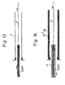
- FIG. 13 through 15 are cross-sectional views illustrating various steps of the manufacturing method according to the second embodiment in order.
- an inner layer 2 composed of a resin absorbent material 2A is pulled using a pull rope (or belt) 4 in the direction indicated by arrows (to the right in Fig. 13) to insert the same into a guiding tube 3.
- the guiding tube 3 is composed of a tubular film, a tubular composite film or a composite structure having layered plastic film and unwoven fabric or split fiber, in a manner similar to the first embodiment.
- the inner and outer surfaces of the guiding tube 3 are smooth, and the outer peripheral surface is applied with a lubricant such as oil, liquid or powder wax. Therefore, the inner layer 2 can be smoothly inserted into the guiding tube 3 without resistance.
- an outer layer 1 composed of a tubular resin absorbent material 1A and a plastic film 1B covering the outer periphery of the resin absorbent material 1A is prepared, and one end thereof is fixed. Then, the inner layer 2 covered with the guiding tube 3 is pulled using the pull rope (or belt) 4 in the direction indicated by arrows (to the right in Fig. 14) to insert the same into the outer layer 1. It should be noted that in this event, since the outer peripheral surface of the guiding tube 3 is also applied with a lubricant such as oil, the insertion of the inner layer 2 covered with the guiding tube 3 into the outer layer 1 can be carried out smoothly.
- the respective resin absorbent materials constituting the tubular outer layer 1 and the tubular inner layer 2 are impregnated with thermosetting resin such as unsaturated polyester to provide a pipe liner bag 10 having a two-layer structure of the outer layer 1 and the inner layer 2, similar to that illustrated in Fig. 4.
- outer layer 1 and the inner layer 2 used in the second embodiment are manufactured in a manner similar to those used in the first embodiment, and the inner layer 2 has a diameter larger than the outer layer 1, as is the case of the first embodiment.
- the second embodiment can also manufacture the outer layer 1 and the inner layer 2 separately, similar effects to those of the first embodiment can be provided.
- the inner layer 2 covered with the guiding tube 3 since the inner layer 2 covered with the guiding tube 3 is inserted into the outer layer 1, the inner layer 2 can be smoothly inserted into the outer layer 1.
- the guiding tube 3 is extracted when the inner layer 2 has been completely inserted, so that the outer layer 1 and the inner layer 2 can be readily laminated to provide a multi-layer structure, thereby making it possible to manufacture a pipe liner bag 10 having a desired thickness with a good workability.
- Fig. 16 is a partial cross-sectional view illustrating a manufacturing method according to the third embodiment of the present invention.
- a guiding tube 3' has been previously inserted inside out into an outer layer 1 by fluid pressure similar to that illustrated in Fig. 1, and an inner layer 2 covered with a guiding tube 3 is pulled using a pull rope (or belt) 4 in the direction indicated by the arrow (to the right in Fig. 16) to insert the same into the guiding tube 3', with one end of the outer layer 1 and one end of the guiding tube 3' being fixed, as illustrated in Fig. 16. Thereafter, the two guiding tubes 3, 3' are extracted with the outer layer 1 and the inner layer 2 being fixed.
- the outer layer and the inner layer are separately manufactured, and the manufacturing of each layer can be performed with a good workability.
- the plastic film coated on the outer peripheral surface of the outer layer is prevented from scratches.
- the inner layer is inserted into the outer layer as the inner layer is guided by the guiding tube, so that the inner layer can be smoothly inserted into the outer layer.
- the guiding tube is extracted to readily laminate the outer layer and the inner layer to provide a multi-layer structure.
- the resin absorbent materials of the tubular outer layer and the tubular inner layer are impregnated with thermosetting resin. In this way, a pipe liner bag having a desired thickness can be manufactured with a good workability.
Description
- The present invention relates to a method of manufacturing a pipe liner bag for use in repairing pipelines.
- When an underground pipe, such as a pipeline or passageway, becomes defective or too old to perform properly, the pipe is repaired and without digging the earth to expose the pipe and disassembling the sections of the pipe. This non-digging method of repairing an underground pipe has been known and practiced commonly in the field of civil engineering. The pipe lining method utilizes a tubular pipe liner bag made of a resin absorbent material impregnated with a hardenable resin, and having the outer surface covered with a highly air-tight plastic film. The tubular pipe liner bag is inserted into a pipe to be repaired by means of a pressurized fluid such that the pipe liner bag is turned inside out as it proceeds deeper in the pipe. Hereinafter, this manner of insertion shall be called "everting". When the entire length of the tubular liner bag is everted (i.e., turned inside out) into the pipe, the everted tubular liner is pressed against the inner wall of the pipe by a pressurized fluid, and the tubular flexible liner is hardened as the hardenable resin impregnated in the liner is heated, which is effected by heating the fluid filling the tubular liner bag. It is thus possible to line the inner wall of the defective or old pipe with a rigid liner without digging the ground and disassembling the pipe sections.
- In the pipe liner bag used in the above-mentioned pipe lining method, the thickness of the material of the pipe liner bag is adjusted in order to ensure a required strength. The adjustment of the thickness is typically made by laminating a plurality of resin absorbent materials to form a multi-layer structure.
- For example, when a pipe liner bag is formed of two tubular layers of resin absorbent materials for ensuring a required thickness, a resin absorbent material made of unwoven fabric is first rolled and both ends are joined to form a first tubular layer of resin absorbent material. Then, another strip-like resin absorbent material is surrounded over the first layer of resin absorbent material and both ends are joined to form a second tubular layer of resin absorbent material. Then, the outer surface of the two-layer resin absorbent material is coated with a plastic film. In this way, a pipe liner bag having a desired thickness is manufactured.
- The process of coating the outer surface of the resin absorbent material with the plastic film involves the most expertise in the method of manufacturing the multi-layer pipe liner bag. However, since this coating is performed on a heavy multi-layer resin absorbent material, there is a problem that the workability is extremely low. Particularly, for manufacturing a large-diameter and thick pipe liner bag, an operation for modifying a large and heavy pipe liner bag deviated from a machining line is difficult, and the plastic film covering the outer surface of the pipe liner bag is often scratched during treatment of the pipe liner bag.
- In addition, a process of surrounding a strip-like resin absorbent material over the outer periphery of the tubular-formed first resin absorbent material to form a second and subsequent layers of resin absorbent materials is also difficult, so that a large amount of labour and time is required.
- Attention is also drawn to the disclosures of EP-A-0620104, EP-A-0548417, and EP-A-0412752.
- The present invention has been made in view of the problems mentioned above, and it is an object of the invention to provide a method which is capable of readily manufacturing a multi-layer pipe liner bag with a good workability.
- To achieve the above object, according to one aspect of the present invention there is provided a method of manufacturing a pipe liner bag, comprising the steps of:
- preparing a tubular outer layer composed of a resin absorbent material and a plastic film coated over the outer periphery of the resin absorbent material;
- inserting a guiding tube into the outer layer;
- inserting a tubular inner layer composed of another resin absorbent material into said guiding tube;
- extracting the guiding tube with the outer layer and the inner layer being laminated; and
- impregnating the resin absorbent materials of the outer layer and the inner layer with thermosetting resin.
-
- According to a second aspect of the present invention, there is provided a method of manufacturing a pipe liner bag, comprising the steps of:
- inserting a tubular inner layer composed of a tubular resin absorbent material into a guiding tube;
- preparing a tubular outer layer composed of another resin absorbent material and a plastic film coated over the outer periphery of the resin absorbent material;
- inserting the inner layer covered with the guiding tube into the outer layer;
- extracting the guiding tube with the outer layer and the inner layer being laminated; and
- impregnating the resin absorbent materials of the outer layer and the inner layer with thermosetting resin.
-
- According to a third aspect of the present invention, there is provided a method of manufacturing a pipe liner bag, comprising the steps of:
- preparing a tubular outer layer composed of a resin absorbent material and a plastic film coated over the outer periphery of the resin absorbent material;
- inserting a first guiding tube into the outer layer;
- inserting a tubular inner layer composed of another resin absorbent material into a second guiding tube;
- inserting the inner layer covered with the second guiding tube into the first guiding tube;
- extracting the first and second guiding tubes with the outer layer and the inner layer being laminated; and
- impregnating the respective resin absorbent materials of the outer layer and the inner layer with thermosetting resin.
-
- Preferably, the guiding tube is inserted inside out into the outer layer by a fluid pressure.
- Also preferably, the guiding tube is composed of a tubular film, a tubular composite film or a composite structure having layered plastic film and unwoven fabric or split fiber.
- Further preferably, the guiding tube is applied with a lubricant.
- The methods described above may further comprise the steps of:
- after extracting the guiding tube, fixing one end of the outer layer and one end of the inner layer with a bolt, a nut, and washers;
- sealing the outer layer and the inner layer with an end cover; and
- covering the bolt, the nut, and the washers with a jacket.
-
- The tubular outer layer may be manufactured by inserting a resin absorbent material into the plastic film, evacuating the resin absorbent material to bring the plastic film into close contact with the outer surface of the resin absorbent material, and heating the plastic film while maintaining the closely contacted state to weld the plastic film on the outer surface of the resin absorbent material.
- In this case, a highly air-tight pressure tube is inserted into the resin absorbent material, the pressure tube is inflated with a fluid pressure to extend the plastic film and the resin absorbent material outwardly in a circular tube shape, and the resin absorbent material is evacuated to bring the plastic film into close contact with the outer surface of the resin absorbent material.
- The outer layer may be manufactured by rolling a strip-like resin absorbent material having a plastic film coated over one surface thereof with the plastic film facing the outside, joining both ends, and hermetically sealing the joined portion.
- Thus, according to the present invention, the outer layer and the inner layer are separately manufactured, and the manufacturing of each layer can be performed with a good workability. In addition, the plastic film coated on the outer peripheral surface of the outer layer is prevented from scratches. Furthermore, the inner layer is inserted into the outer layer as the inner layer is guided by the guiding tube, so that the inner layer can be smoothly inserted into the outer layer. Once the inner layer has been completely inserted, the guiding tube is extracted to readily laminate the outer layer and the inner layer to provide a multi-layer structure. Then, the resin absorbent materials of the tubular outer layer and the tubular inner layer are impregnated with thermosetting resin. In this way, a pipe liner bag having a desired thickness can be manufactured with a good workability.
- The invention will be further described with reference to the accompanying drawings, wherein:
- Figs. 1 through 3 are cross-sectional views illustrating, in order, the steps of a manufacturing method according to a first embodiment of the present invention;
- Fig. 4 is a partial perspective view illustrating a pipe liner bag manufactured by the manufacturing method according to the first embodiment;
- Fig. 5 is an enlarged view illustrating in detail an end machined portion of the pipe liner bag manufactured by the manufacturing method according to the first embodiment;
- Fig. 6 through 9 are explanatory diagrams illustrating, in order, various steps of a method of manufacturing an outer layer;
- Fig. 10 is a cross-sectional view illustrating an evacuated resin absorbent material;
- Figs. 11 and 12 are partial perspective views illustrating another method of manufacturing the outer layer;
- Figs. 13 through 15 are cross-sectional views illustrating, in order, the steps of a manufacturing method according to a second embodiment of the present invention; and
- Fig. 16 is a partial cross-sectional view illustrating a manufacturing method according to a third embodiment of the present invention.
-
- The present invention will hereinafter be described in connection with several preferred embodiments thereof with reference to the accompanying drawings.
- First, a first embodiment of the present invention will be described. Figs. 1 through 3 are cross-sectional views illustrating, in order, the steps of a manufacturing method according to the first embodiment. Fig. 4 is a partial perspective view illustrating a pipe liner bag manufactured by the method according to the first embodiment, and Fig. 5 is an enlarged view illustrating in detail an end machined portion of the pipe liner bag.
- In the method of the first embodiment, a guiding
tube 3 is inserted inside out by a fluid pressure such as air pressure or the like, by way of example, into a tubular outer layer 1 composed of a resinabsorbent material 1A and a highly air-tight plastic film 1B covering the outer periphery of the resinabsorbent material 1A, as illustrated in Fig. 1. The guidingtube 3 is composed of a tubular film, a tubular composite film or a composite structure having layered plastic film and unwoven fabric or split fiber. The inner and outer surfaces of the guidingtube 3 are smooth, and the outer peripheral surface, before eversion, is applied with a lubricant such as oil, liquid or powder wax. Therefore, when the guidingtube 3 is inserted inside out into the outer layer 1, the inner peripheral surface of the guidingtube 3 is applied with a lubricant such as oil. As can be seen in Fig. 1, a pull rope (or belt) 4 is connected at an end portion of the guidingtube 3. - When the guiding
tube 3 has been completely everted into the outer layer 1 over the entire length thereof, the pull rope (or belt) 4 is drawn into the guidingtube 3. In this event, one end of the pull rope (or belt) 4 is attached to one end of a tubularinner layer 2 comprising another resinabsorbent material 2A, as illustrated in Fig. 2. It should be noted that the diameter of the resinabsorbent material 2A constituting the tubularinner layer 2 is set larger than the diameter of the resinabsorbent material 1A constituting the tubular outer layer 1. - Then, as illustrated in Fig. 2, the
pull rope 4 is pulled in the direction indicated by arrows (to the right in Fig. 2), with the outer layer 1 and guidingtube 3 fixed at one end thereof, to pull theinner layer 2 into the guidingtube 3. In this event, since the inner peripheral surface of the guidingtube 3 is applied with a lubricant such as oil, theinner layer 2 is smoothly inserted into the guidingtube 3 without resistance. - Next, referring to Fig. 3, after the
inner layer 2 has been inserted in the guidingtube 3 over the entire length thereof, the guidingtube 3 is pulled by way of a pull rope (or belt) 5 in the direction indicated by the arrow (to the left in Fig. 3) to extract the guidingtube 3. This results in theinner layer 2 being attached to the outer layer 1. End portions of theselayers 1, 2 undergo end machining as illustrated in detail in Fig. 5. - The end machining is performed in the following manner.
- First, one end of the outer layer 1 and one end of the
inner layer 2 are fixed using abolt 6, anut 7, andwashers 8, 9, and end faces of the outer layer 1 and theinner layer 2 are covered with a highly air-tight end cover 11. It should be noted that theend cover 11 is integrally formed with anair vent duct 11a which is tied as illustrated, when ventilation is terminated for the outer layer 1 and theinner layer 2, to prevent air from passing into or exiting from the internal space. -
Base members 12 are adhered on both surfaces of the outer layer 1 through which thebolt 6 extends, and a pullrope attaching belt 13 and a hotwater attaching belt 14 are fixed by thebolt 6 at end portions of the outer layer 1 and theinner layer 2. Thebolt 6, thenut 7, and thewashers 8, 9, exposed to the outside, are covered with ajacket 15. Thebase members 12 and thejacket 15 are made by coating one surface of unwoven fabric with a plastic film. - When the above-described end machining is terminated, the respective resin absorbent materials constituting the tubular outer layer 1 and the tubular
inner layer 2 are impregnated with thermosetting resin such as unsaturated polyester to provide apipe liner bag 10 having a two-layer structure of the outer layer 1 and theinner layer 2, as illustrated in Fig. 4. - According to the present invention, the outer layer 1 and the
inner layer 2 may be manufactured individually. A method of manufacturing the outer layer 1 will be described below with reference to Figs. 6 through 10. Fig. 6 through 9 are explanatory diagrams illustrating various steps of the method of manufacturing the outer layer 1 in order, and Fig. 10 is a cross-sectional view illustrating an evacuated resinabsorbent material 1A. - In the manufacturing of the outer layer 1, first, both edges in the width direction of a resin
absorbent material 1A cut into a strip shape are overlapped, and the overlapping edge portions are sewed together (lock sewing) into a tubular shape, as illustrated in Fig. 6. After the sewing operation is completed, the seam is stretched in the circumferential direction to form a resinabsorbent material 1A which has both the edges in the width direction abutted to each other, as illustrated in Fig. 7. Here, the resinabsorbent material 1A is made of high melting point unwoven fabric comprising polyester, acrylic, nylon, glass, carbon, ceramic, and so on, or a mixture thereof. - Other than the lock sewing, the resin
absorbent material 1A may be made by joining the abutted edges of the strip resinabsorbent material 1A by straight sewing, punching using needles, welding, bonding using a bonding agent, or the like. - Next, as illustrated in Fig. 9, the resin-
absorbent material 1A is inserted into a seamless tubularplastic film 1B, and a highly air-tight pressure tube 16 is also inserted into the resinabsorbent material 1A. The plastic film may be made of polyethylene, polypropylene, nylon, polyvinyl chloride, or the like. - Next, in the state illustrated in Fig. 8, both ends of the
pressure tube 16 are closed to hermetically seal thepressure tube 16. Then, as illustrated in Fig. 9, when compressed air is supplied into thepressure tube 16 from acompressor 17 through anair hose 18, thepressure tube 16 is inflated by the pressure applied by the compressed air to extend the resinabsorbent material 1A and theplastic film 1B outwardly in a circular tube shape. - Next, with the above-mentioned state maintained unchanged, the resin
absorbent material 1A is evacuated using avacuum pump 19 and avacuum hose 20, as illustrated in Figs. 9 and 10, such that theplastic film 1B located outside the resinabsorbent material 1A is attracted by negative pressure generated within the resinabsorbent material 1A to come into close contact with the outer surface of the resinabsorbent material 1A. - Subsequently, the resin
absorbent material 1A together with theplastic film 1B and thepressure tube 16 is passed through acylindrical heating apparatus 21, as illustrated in Fig. 9. Thetubular assembly heating apparatus 21 is being driven, to move the tubular assembly over the entire length thereof through theheating apparatus 21 in the direction indicated by the arrow. Consequently, theplastic film 1B is heated by theheating apparatus 21 and gradually welded on the outer peripheral surface of the resinabsorbent material 1A, whereby the outer peripheral surface of the resinabsorbent material 1A is covered with theplastic film 1B. Theheating apparatus 21 may comprise a plurality of linearelectric heaters 24 obliquely mounted on the inner wall surface of a cylinder 23 having a diameter sufficiently larger than that of the resinabsorbent material 1A. When theelectric heaters 24 are powered from apower supply 25, theelectric heaters 24 generate heat which is applied to theplastic film 1B for heating. - In the alternative, the outer layer 1 may be manufactured by a method illustrated in Figs. 11 and 12. Figs. 11 and 12 are partial perspective views illustrating another method of manufacturing the outer layer 1.
- Specifically, as illustrated in Fig. 11, a strip-like resin
absorbent material 1A having aplastic film 1B coated over one surface thereof is rolled with theplastic film 1B facing the outside, and both ends are joined by sewing. Then, an elongateunwoven fabric strip 1a is adhered by a thermal adhesive on the outer periphery of the resinabsorbent material 1A along the joined portion to hermetically seal the joined portion. In this way, the outer layer 1 may also be provided. A polyethylene or nylon group thermal adhesive may be used as the thermal adhesive of this embodiment. - The
inner layer 2 is manufactured by a method similar to that described with reference to Figs. 6 and 7. - Specifically, though not shown, both edges in the width direction of a resin
absorbent material 2A cut into a strip shape are overlapped, and the overlapping edge portions are sewed together (lock sewing) into a tubular shape. After the sewing operation is completed, the seam is stretched in the circumferential direction to form a resinabsorbent material 2A which has both the edges in the width direction abutted to each other. Here, a specific material for the resinabsorbent material 2A may be selected from those used for the resinabsorbent material 1A of the outer layer 1. - Other than the lock sewing, the resin
absorbent material 2A may be made by joining the abutted edges of the strip resinabsorbent material 2A by straight sewing, punching using needles, welding, bonding using a bonding agent, or the like. - According to this embodiment, since the outer layer 1 and the
inner layer 2 can be manufactured individually, the respective manufacturing processes can be carried out with a high workability. In particular, theplastic film 1B coated over the outer surface of the outer layer 1 will not be scratched. - In addition, since the
inner layer 2 is inserted into the inside of the outer layer 1 with the guidingtube 3 guiding theinner layer 2, theinner layer 2 can be smoothly inserted into the inside of the outer layer 1. When theinner layer 2 is inserted, the guidingtube 3 is extracted, so that the outer layer 1 and theinner layer 2 are laminated to provide a multi-layer structure. Then, the resinabsorbent materials pipe liner bag 10 having a desired thickness with a high workability. - Next, a method of manufacturing a pipe liner bag according to a second embodiment will be described with reference to Figs. 13 through 15. Figs. 13 through 15 are cross-sectional views illustrating various steps of the manufacturing method according to the second embodiment in order.
- Referring first to Fig. 13, an
inner layer 2 composed of a resinabsorbent material 2A is pulled using a pull rope (or belt) 4 in the direction indicated by arrows (to the right in Fig. 13) to insert the same into a guidingtube 3. Here, the guidingtube 3 is composed of a tubular film, a tubular composite film or a composite structure having layered plastic film and unwoven fabric or split fiber, in a manner similar to the first embodiment. The inner and outer surfaces of the guidingtube 3 are smooth, and the outer peripheral surface is applied with a lubricant such as oil, liquid or powder wax. Therefore, theinner layer 2 can be smoothly inserted into the guidingtube 3 without resistance. - Next, referring to in Fig. 14, an outer layer 1 composed of a tubular resin
absorbent material 1A and aplastic film 1B covering the outer periphery of the resinabsorbent material 1A is prepared, and one end thereof is fixed. Then, theinner layer 2 covered with the guidingtube 3 is pulled using the pull rope (or belt) 4 in the direction indicated by arrows (to the right in Fig. 14) to insert the same into the outer layer 1. It should be noted that in this event, since the outer peripheral surface of the guidingtube 3 is also applied with a lubricant such as oil, the insertion of theinner layer 2 covered with the guidingtube 3 into the outer layer 1 can be carried out smoothly. - Next, referring to Fig. 15, once the
inner layer 2 covered with the guidingtube 3 has been inserted into the outer layer 1 over the entire length thereof in the manner mentioned above, the guidingtube 3 is pulled by the pull rope (or belt) 5 in the direction indicated by the arrow (to the left in Fig. 15) to extract the same, with the outer layer 1 and theinner layer 2 being fixed. Subsequently, the outer layer 1 and theinner layer 2 are laminated, and end portions of theselayers 1, 2 undergo end machining similar to that illustrated in Fig. 5. - After the end machining is terminated, the respective resin absorbent materials constituting the tubular outer layer 1 and the tubular
inner layer 2 are impregnated with thermosetting resin such as unsaturated polyester to provide apipe liner bag 10 having a two-layer structure of the outer layer 1 and theinner layer 2, similar to that illustrated in Fig. 4. - It should be noted that the outer layer 1 and the
inner layer 2 used in the second embodiment are manufactured in a manner similar to those used in the first embodiment, and theinner layer 2 has a diameter larger than the outer layer 1, as is the case of the first embodiment. - Thus, since the second embodiment can also manufacture the outer layer 1 and the
inner layer 2 separately, similar effects to those of the first embodiment can be provided. - In addition, since the
inner layer 2 covered with the guidingtube 3 is inserted into the outer layer 1, theinner layer 2 can be smoothly inserted into the outer layer 1. The guidingtube 3 is extracted when theinner layer 2 has been completely inserted, so that the outer layer 1 and theinner layer 2 can be readily laminated to provide a multi-layer structure, thereby making it possible to manufacture apipe liner bag 10 having a desired thickness with a good workability. - Next, a third embodiment of the present invention will be described with reference to Fig. 16. Fig. 16 is a partial cross-sectional view illustrating a manufacturing method according to the third embodiment of the present invention.
- While the third embodiment is generally similar to the first embodiment, a guiding tube 3' has been previously inserted inside out into an outer layer 1 by fluid pressure similar to that illustrated in Fig. 1, and an
inner layer 2 covered with a guidingtube 3 is pulled using a pull rope (or belt) 4 in the direction indicated by the arrow (to the right in Fig. 16) to insert the same into the guiding tube 3', with one end of the outer layer 1 and one end of the guiding tube 3' being fixed, as illustrated in Fig. 16. Thereafter, the two guidingtubes 3, 3' are extracted with the outer layer 1 and theinner layer 2 being fixed. Then, resinabsorbent materials inner layer 2 are impregnated with thermosetting resin to manufacture apipe liner bag 10 similar to that illustrated in Fig. 4. It should be noted that at least one of the outer peripheral surface of the guidingtube 3 and the inner peripheral surface of the guiding tube 3' is applied with a lubricant such as oil, so that the insertion of theinner layer 2 covered with the guidingtube 3 into the guiding tube 3' is smoothly carried out. Therefore, the third embodiment can also provide similar effects to those of the first and second embodiments. - As will be apparent from the foregoing description, according to the present invention, the outer layer and the inner layer are separately manufactured, and the manufacturing of each layer can be performed with a good workability. In addition, the plastic film coated on the outer peripheral surface of the outer layer is prevented from scratches.
- Also, according to the present invention, the inner layer is inserted into the outer layer as the inner layer is guided by the guiding tube, so that the inner layer can be smoothly inserted into the outer layer. Once the inner layer has been completely inserted, the guiding tube is extracted to readily laminate the outer layer and the inner layer to provide a multi-layer structure. Then, the resin absorbent materials of the tubular outer layer and the tubular inner layer are impregnated with thermosetting resin. In this way, a pipe liner bag having a desired thickness can be manufactured with a good workability.
- While the present invention has been described in connection with its preferred embodiments, it is to be understood that various modifications will occur to those skilled in the art without departing from the scope of the invention.
Claims (10)
- A method of manufacturing a pipe liner bag (10), comprising the steps of:preparing a tubular outer layer (1) composed of a resin absorbent material (1A) and a plastic film (1B) coated over the outer periphery of the resin absorbent material;inserting a guiding tube (3) into said outer layer (1);inserting a tubular inner layer (2) composed of another resin absorbent material (2A) into said guiding tube (3);extracting said guiding tube (3) with said outer layer (1) and said inner layer (2) being laminated; andimpregnating the resin absorbent materials of said outer layer (1) and said inner layer (2) with thermosetting resin.
- A method of manufacturing a pipe liner bag (10), comprising the steps of:inserting a tubular inner layer (2) composed of a resin absorbent material (2A) into a guiding tube (3);preparing a tubular outer layer (1) composed of another resin absorbent material (1A) and a plastic film (1B) coated over the outer periphery of the resin absorbent material;inserting said inner layer (2) covered with said guiding tube (3) into said outer layer (1);extracting said guiding tube (3) with said outer layer (1) and said inner layer (2) being laminated; andimpregnating the resin absorbent materials of said outer layer (1) and said inner layer (2) with thermosetting resin.
- A method of manufacturing a pipe liner bag (10), comprising the steps of:preparing a tubular outer layer (1) composed of a resin absorbent material (1A) and a plastic film (1B) coated over the outer periphery of the resin absorbent material;inserting a first guiding tube (3') into said outer layer (1);inserting a tubular inner layer (2) composed of another resin absorbent material (2A) into a second guiding tube (3);inserting said inner layer (2) covered with said second guiding tube (3) into said first guiding tube (3');extracting said first and second guiding tubes (3',3) with said outer layer (1) and said inner layer (2) being laminated; andimpregnating said respective resin absorbent materials (1A,2A) of said outer layer (1) and said inner layer (2) with thermosetting resin.
- A method as claimed in any of claims 1 to 3, characterized in that said guiding tube (3) is inserted inside out into said outer layer (1) by a fluid pressure.
- A method as claimed in any of claims 1 to 4, characterized in that said guiding tube (3) is composed of a tubular film, a tubular composite film or a composite structure having layered plastic film and unwoven fabric or split fiber.
- A method as claimed in any of claims 1 to 5, characterized in that said guiding tube (3) is applied with a lubricant.
- A method as claimed in any of claims 1 to 6, characterized by further comprising the step of: after extracting said guiding tube (3), fixing one end of said outer layer (1) and one end of said inner layer (2) with a bolt (6), a nut (7), and washers (8,9); sealing said outer layer and said inner layer with an end cover (11); and covering the bolt, the nut, and the washers with a jacket (15).
- A method as claimed in any of claims 1 to 7, characterized in that said tubular outer layer (1) is manufactured by inserting a resin absorbent material (1A) into said plastic film (1B), evacuating said resin absorbent material to bring said plastic film into close contact with the outer surface of said resin absorbent material, and heating said plastic film while maintaining the closely contacted state to weld said plastic film on the outer surface of said resin absorbent material.
- A method as claimed in claim 9, characterized in that a highly air-tight pressure tube (16) is inserted into said resin absorbent material, said pressure tube is inflated with a fluid pressure to extend said plastic film and said resin absorbent material outwardly in a circular tube shape, and said resin absorbent material is evacuated to bring said plastic film into close contact with the outer surface of said resin absorbent material.
- A method as claimed in any of claims 1 to 7, characterized in that said outer layer (1) is manufactured by rolling a strip-like resin absorbent material (1A) having a plastic film (1B) coated over one surface thereof with the plastic film facing the outside, joining both ends, and hermetically sealing the joined portion.
Applications Claiming Priority (3)
| Application Number | Priority Date | Filing Date | Title |
|---|---|---|---|
| JP310562/96 | 1996-11-21 | ||
| JP8310562A JP2974130B2 (en) | 1996-11-21 | 1996-11-21 | Manufacturing method of pipe lining material |
| JP31056296 | 1996-11-21 |
Publications (3)
| Publication Number | Publication Date |
|---|---|
| EP0844065A2 EP0844065A2 (en) | 1998-05-27 |
| EP0844065A3 EP0844065A3 (en) | 2000-05-17 |
| EP0844065B1 true EP0844065B1 (en) | 2003-04-09 |
Family
ID=18006745
Family Applications (1)
| Application Number | Title | Priority Date | Filing Date |
|---|---|---|---|
| EP97306971A Expired - Lifetime EP0844065B1 (en) | 1996-11-21 | 1997-09-09 | Method of manufacturing a pipe liner bag |
Country Status (9)
| Country | Link |
|---|---|
| US (1) | US6136135A (en) |
| EP (1) | EP0844065B1 (en) |
| JP (1) | JP2974130B2 (en) |
| KR (1) | KR19980041875A (en) |
| AU (1) | AU724669B2 (en) |
| CA (1) | CA2221595A1 (en) |
| DE (1) | DE69720655T2 (en) |
| DK (1) | DK0844065T3 (en) |
| TW (1) | TW338742B (en) |
Cited By (1)
| Publication number | Priority date | Publication date | Assignee | Title |
|---|---|---|---|---|
| EP3174703B1 (en) | 2014-07-31 | 2020-06-03 | SML Verwaltungs GmbH | Tubular liner for the rehabilitation of fluid-conducting pipeline systems |
Families Citing this family (10)
| Publication number | Priority date | Publication date | Assignee | Title |
|---|---|---|---|---|
| AU742515B2 (en) * | 1997-06-24 | 2002-01-03 | Lmk Technologies, Llc | Apparatus for repairing a pipeline and method for using same |
| US6481928B1 (en) * | 1997-09-22 | 2002-11-19 | David Doolaege | Flexible hydraulic structure and system for replacing a damaged portion thereof |
| JP3790052B2 (en) * | 1998-09-25 | 2006-06-28 | 株式会社湘南合成樹脂製作所 | Manufacturing method of pipe lining material |
| JP3839605B2 (en) * | 1998-12-22 | 2006-11-01 | 株式会社湘南合成樹脂製作所 | Manhole lining material |
| US20050281970A1 (en) * | 2004-06-16 | 2005-12-22 | Lamarca Louis J Ii | Lateral liner substrates |
| JP2010201887A (en) * | 2009-03-06 | 2010-09-16 | Shonan Plastic Mfg Co Ltd | Pipe-lining material |
| DK2343179T3 (en) * | 2010-01-12 | 2015-02-09 | Twe Group Gmbh | Ultrasonic and laser welding for rørsanering |
| JP5530880B2 (en) * | 2010-09-28 | 2014-06-25 | 東海ゴム工業株式会社 | Soundproof cover for tube and tube with cover |
| DK2777925T3 (en) | 2013-03-11 | 2021-08-09 | Buergofol GmbH | Inlet hose for excavation-free sewer pipe renovation |
| GB2580957B (en) * | 2019-01-31 | 2021-11-03 | W E Rawson Ltd | Improvements relating to pipe liners |
Family Cites Families (10)
| Publication number | Priority date | Publication date | Assignee | Title |
|---|---|---|---|---|
| ATE35647T1 (en) * | 1982-02-05 | 1988-07-15 | Edgealpha Ltd | LINING OF PIPES OR PLUMES. |
| JPH0723240Y2 (en) * | 1988-09-16 | 1995-05-31 | 日本鋼管株式会社 | Tube used for pipe lined construction method |
| US5407630A (en) * | 1989-03-21 | 1995-04-18 | Insituform (Netherlands) Bv | Lining of pipelines or passageways |
| CA2000955A1 (en) * | 1989-08-07 | 1991-02-07 | Lyman R. Lyon | Pipe liner and method of installation thereof |
| JPH0745182B2 (en) * | 1990-06-29 | 1995-05-17 | 株式会社ゲット | Method for manufacturing pipe lining material |
| JP2554411B2 (en) * | 1991-05-31 | 1996-11-13 | 株式会社ゲット | Branch pipe lining material and manufacturing method thereof |
| JPH08426B2 (en) * | 1993-04-13 | 1996-01-10 | 株式会社湘南合成樹脂製作所 | Pipe lining material and its manufacturing method and pipe repair method |
| AU742515B2 (en) * | 1997-06-24 | 2002-01-03 | Lmk Technologies, Llc | Apparatus for repairing a pipeline and method for using same |
| JP2702086B2 (en) * | 1995-02-13 | 1998-01-21 | 株式会社湘南合成樹脂製作所 | Manufacturing method of pipe lining material |
| JP2837384B2 (en) * | 1996-03-19 | 1998-12-16 | 株式会社湘南合成樹脂製作所 | Pipe lining method |
-
1996
- 1996-11-21 JP JP8310562A patent/JP2974130B2/en not_active Expired - Fee Related
-
1997
- 1997-09-04 TW TW086112775A patent/TW338742B/en active
- 1997-09-04 KR KR1019970045835A patent/KR19980041875A/en not_active Application Discontinuation
- 1997-09-09 EP EP97306971A patent/EP0844065B1/en not_active Expired - Lifetime
- 1997-09-09 DK DK97306971T patent/DK0844065T3/en active
- 1997-09-09 DE DE69720655T patent/DE69720655T2/en not_active Expired - Fee Related
- 1997-11-20 US US08/974,835 patent/US6136135A/en not_active Expired - Fee Related
- 1997-11-20 CA CA002221595A patent/CA2221595A1/en not_active Abandoned
- 1997-11-21 AU AU45345/97A patent/AU724669B2/en not_active Ceased
Cited By (1)
| Publication number | Priority date | Publication date | Assignee | Title |
|---|---|---|---|---|
| EP3174703B1 (en) | 2014-07-31 | 2020-06-03 | SML Verwaltungs GmbH | Tubular liner for the rehabilitation of fluid-conducting pipeline systems |
Also Published As
| Publication number | Publication date |
|---|---|
| AU724669B2 (en) | 2000-09-28 |
| CA2221595A1 (en) | 1998-05-21 |
| JP2974130B2 (en) | 1999-11-08 |
| DE69720655T2 (en) | 2003-12-24 |
| US6136135A (en) | 2000-10-24 |
| KR19980041875A (en) | 1998-08-17 |
| EP0844065A2 (en) | 1998-05-27 |
| DE69720655D1 (en) | 2003-05-15 |
| AU4534597A (en) | 1998-06-04 |
| JPH10151672A (en) | 1998-06-09 |
| EP0844065A3 (en) | 2000-05-17 |
| TW338742B (en) | 1998-08-21 |
| DK0844065T3 (en) | 2003-07-14 |
Similar Documents
| Publication | Publication Date | Title |
|---|---|---|
| US6296729B1 (en) | Method of manufacturing pipe liner bag | |
| US6254709B1 (en) | Method of manufacturing a pipe liner bag | |
| EP0978681B1 (en) | Branch pipe liner bag and pipe lining method | |
| EP0844065B1 (en) | Method of manufacturing a pipe liner bag | |
| US6006787A (en) | Branch pipe liner bag and branch pipe lining method | |
| EP0931639A2 (en) | Pipe lining method | |
| US6085794A (en) | Pipe lining method | |
| JPH0459227A (en) | Manufacture of tubular lining material | |
| US5163481A (en) | Tubular liner for softlining pipe rehabilitation | |
| JP2719312B2 (en) | Joining method of pipe lining material | |
| EP0844076B1 (en) | Pipe liner bag and manufacturing method therefor | |
| JP2644437B2 (en) | Branch pipe lining method | |
| JP2678151B2 (en) | Pipe lining material and method of manufacturing the same | |
| JPH11235758A (en) | Production of pipe lining material and pipe lining method | |
| JP2845798B2 (en) | Branch pipe lining material and branch pipe lining method | |
| JP3049283B2 (en) | Manufacturing method of pipe lining material | |
| JP2678149B2 (en) | Branch pipe lining material and branch pipe lining method | |
| JP2737105B2 (en) | Branch pipe lining material and branch pipe lining method | |
| JPH07125069A (en) | Production of pipe lining material | |
| JP2702099B2 (en) | Start liner with flange for branch pipe and pipe lining method | |
| JP2737104B2 (en) | Joining method of pipe lining material | |
| JP2022021015A (en) | Method for connecting pipe lining materials, and connection apparatus | |
| AU4530597A (en) | Pipe liner bag and manufacturing method therefor | |
| JP2932358B2 (en) | Pipe lining method | |
| JPH1080950A (en) | Bonding structure of pipe lining material |
Legal Events
| Date | Code | Title | Description |
|---|---|---|---|
| PUAI | Public reference made under article 153(3) epc to a published international application that has entered the european phase |
Free format text: ORIGINAL CODE: 0009012 |
|
| AK | Designated contracting states |
Kind code of ref document: A2 Designated state(s): DE DK FR GB |
|
| PUAL | Search report despatched |
Free format text: ORIGINAL CODE: 0009013 |
|
| AK | Designated contracting states |
Kind code of ref document: A3 Designated state(s): AT BE CH DE DK ES FI FR GB GR IE IT LI LU MC NL PT SE |
|
| 17P | Request for examination filed |
Effective date: 20001108 |
|
| AKX | Designation fees paid |
Free format text: DE DK FR GB |
|
| 17Q | First examination report despatched |
Effective date: 20010521 |
|
| GRAH | Despatch of communication of intention to grant a patent |
Free format text: ORIGINAL CODE: EPIDOS IGRA |
|
| GRAH | Despatch of communication of intention to grant a patent |
Free format text: ORIGINAL CODE: EPIDOS IGRA |
|
| GRAA | (expected) grant |
Free format text: ORIGINAL CODE: 0009210 |
|
| AK | Designated contracting states |
Designated state(s): DE DK FR GB |
|
| REG | Reference to a national code |
Ref country code: GB Ref legal event code: FG4D |
|
| REG | Reference to a national code |
Ref country code: DK Ref legal event code: T3 |
|
| PG25 | Lapsed in a contracting state [announced via postgrant information from national office to epo] |
Ref country code: GB Free format text: LAPSE BECAUSE OF NON-PAYMENT OF DUE FEES Effective date: 20030909 |
|
| ET | Fr: translation filed | ||
| PG25 | Lapsed in a contracting state [announced via postgrant information from national office to epo] |
Ref country code: DK Free format text: LAPSE BECAUSE OF NON-PAYMENT OF DUE FEES Effective date: 20030930 |
|
| PLBE | No opposition filed within time limit |
Free format text: ORIGINAL CODE: 0009261 |
|
| STAA | Information on the status of an ep patent application or granted ep patent |
Free format text: STATUS: NO OPPOSITION FILED WITHIN TIME LIMIT |
|
| 26N | No opposition filed |
Effective date: 20040112 |
|
| PG25 | Lapsed in a contracting state [announced via postgrant information from national office to epo] |
Ref country code: DE Free format text: LAPSE BECAUSE OF NON-PAYMENT OF DUE FEES Effective date: 20040401 |
|
| GBPC | Gb: european patent ceased through non-payment of renewal fee |
Effective date: 20030909 |
|
| REG | Reference to a national code |
Ref country code: DK Ref legal event code: EBP |
|
| PG25 | Lapsed in a contracting state [announced via postgrant information from national office to epo] |
Ref country code: FR Free format text: LAPSE BECAUSE OF NON-PAYMENT OF DUE FEES Effective date: 20040528 |
|
| REG | Reference to a national code |
Ref country code: FR Ref legal event code: ST |