EP0844012A2 - Filter element assembly and element-replaceable type filter equipped with the same - Google Patents
Filter element assembly and element-replaceable type filter equipped with the same Download PDFInfo
- Publication number
- EP0844012A2 EP0844012A2 EP97118188A EP97118188A EP0844012A2 EP 0844012 A2 EP0844012 A2 EP 0844012A2 EP 97118188 A EP97118188 A EP 97118188A EP 97118188 A EP97118188 A EP 97118188A EP 0844012 A2 EP0844012 A2 EP 0844012A2
- Authority
- EP
- European Patent Office
- Prior art keywords
- filter
- cap
- base
- oil
- seal
- Prior art date
- Legal status (The legal status is an assumption and is not a legal conclusion. Google has not performed a legal analysis and makes no representation as to the accuracy of the status listed.)
- Granted
Links
- 239000012530 fluid Substances 0.000 claims abstract description 13
- 238000001914 filtration Methods 0.000 claims description 22
- 238000000638 solvent extraction Methods 0.000 claims description 10
- 238000004891 communication Methods 0.000 claims description 4
- 238000007789 sealing Methods 0.000 claims description 3
- 238000010276 construction Methods 0.000 abstract description 7
- 239000003921 oil Substances 0.000 description 175
- 230000001012 protector Effects 0.000 description 38
- 238000002485 combustion reaction Methods 0.000 description 26
- 238000012986 modification Methods 0.000 description 9
- 230000004048 modification Effects 0.000 description 9
- 210000000078 claw Anatomy 0.000 description 8
- XAGFODPZIPBFFR-UHFFFAOYSA-N aluminium Chemical compound [Al] XAGFODPZIPBFFR-UHFFFAOYSA-N 0.000 description 4
- 229910052782 aluminium Inorganic materials 0.000 description 4
- 230000000717 retained effect Effects 0.000 description 4
- 230000004308 accommodation Effects 0.000 description 2
- 238000005452 bending Methods 0.000 description 2
- 230000000694 effects Effects 0.000 description 2
- 239000000446 fuel Substances 0.000 description 2
- 239000012535 impurity Substances 0.000 description 2
- 238000012423 maintenance Methods 0.000 description 2
- 239000000463 material Substances 0.000 description 2
- 239000010705 motor oil Substances 0.000 description 2
- 239000011347 resin Substances 0.000 description 2
- 229920005989 resin Polymers 0.000 description 2
- OKTJSMMVPCPJKN-UHFFFAOYSA-N Carbon Chemical compound [C] OKTJSMMVPCPJKN-UHFFFAOYSA-N 0.000 description 1
- 229910052799 carbon Inorganic materials 0.000 description 1
- 239000010419 fine particle Substances 0.000 description 1
- 230000001050 lubricating effect Effects 0.000 description 1
- 230000014759 maintenance of location Effects 0.000 description 1
- 239000002245 particle Substances 0.000 description 1
- 238000005192 partition Methods 0.000 description 1
- 238000004804 winding Methods 0.000 description 1
Images


Classifications
-
- B—PERFORMING OPERATIONS; TRANSPORTING
- B01—PHYSICAL OR CHEMICAL PROCESSES OR APPARATUS IN GENERAL
- B01D—SEPARATION
- B01D29/00—Filters with filtering elements stationary during filtration, e.g. pressure or suction filters, not covered by groups B01D24/00 - B01D27/00; Filtering elements therefor
- B01D29/11—Filters with filtering elements stationary during filtration, e.g. pressure or suction filters, not covered by groups B01D24/00 - B01D27/00; Filtering elements therefor with bag, cage, hose, tube, sleeve or like filtering elements
- B01D29/13—Supported filter elements
- B01D29/15—Supported filter elements arranged for inward flow filtration
- B01D29/21—Supported filter elements arranged for inward flow filtration with corrugated, folded or wound sheets
- B01D29/216—Supported filter elements arranged for inward flow filtration with corrugated, folded or wound sheets with wound sheets
-
- B—PERFORMING OPERATIONS; TRANSPORTING
- B01—PHYSICAL OR CHEMICAL PROCESSES OR APPARATUS IN GENERAL
- B01D—SEPARATION
- B01D29/00—Filters with filtering elements stationary during filtration, e.g. pressure or suction filters, not covered by groups B01D24/00 - B01D27/00; Filtering elements therefor
- B01D29/50—Filters with filtering elements stationary during filtration, e.g. pressure or suction filters, not covered by groups B01D24/00 - B01D27/00; Filtering elements therefor with multiple filtering elements, characterised by their mutual disposition
- B01D29/52—Filters with filtering elements stationary during filtration, e.g. pressure or suction filters, not covered by groups B01D24/00 - B01D27/00; Filtering elements therefor with multiple filtering elements, characterised by their mutual disposition in parallel connection
- B01D29/54—Filters with filtering elements stationary during filtration, e.g. pressure or suction filters, not covered by groups B01D24/00 - B01D27/00; Filtering elements therefor with multiple filtering elements, characterised by their mutual disposition in parallel connection arranged concentrically or coaxially
-
- B—PERFORMING OPERATIONS; TRANSPORTING
- B01—PHYSICAL OR CHEMICAL PROCESSES OR APPARATUS IN GENERAL
- B01D—SEPARATION
- B01D29/00—Filters with filtering elements stationary during filtration, e.g. pressure or suction filters, not covered by groups B01D24/00 - B01D27/00; Filtering elements therefor
- B01D29/96—Filters with filtering elements stationary during filtration, e.g. pressure or suction filters, not covered by groups B01D24/00 - B01D27/00; Filtering elements therefor in which the filtering elements are moved between filtering operations; Particular measures for removing or replacing the filtering elements; Transport systems for filters
-
- B—PERFORMING OPERATIONS; TRANSPORTING
- B01—PHYSICAL OR CHEMICAL PROCESSES OR APPARATUS IN GENERAL
- B01D—SEPARATION
- B01D35/00—Filtering devices having features not specifically covered by groups B01D24/00 - B01D33/00, or for applications not specifically covered by groups B01D24/00 - B01D33/00; Auxiliary devices for filtration; Filter housing constructions
- B01D35/14—Safety devices specially adapted for filtration; Devices for indicating clogging
- B01D35/147—Bypass or safety valves
-
- B—PERFORMING OPERATIONS; TRANSPORTING
- B01—PHYSICAL OR CHEMICAL PROCESSES OR APPARATUS IN GENERAL
- B01D—SEPARATION
- B01D35/00—Filtering devices having features not specifically covered by groups B01D24/00 - B01D33/00, or for applications not specifically covered by groups B01D24/00 - B01D33/00; Auxiliary devices for filtration; Filter housing constructions
- B01D35/14—Safety devices specially adapted for filtration; Devices for indicating clogging
- B01D35/153—Anti-leakage or anti-return valves
-
- B—PERFORMING OPERATIONS; TRANSPORTING
- B01—PHYSICAL OR CHEMICAL PROCESSES OR APPARATUS IN GENERAL
- B01D—SEPARATION
- B01D35/00—Filtering devices having features not specifically covered by groups B01D24/00 - B01D33/00, or for applications not specifically covered by groups B01D24/00 - B01D33/00; Auxiliary devices for filtration; Filter housing constructions
- B01D35/30—Filter housing constructions
-
- B—PERFORMING OPERATIONS; TRANSPORTING
- B01—PHYSICAL OR CHEMICAL PROCESSES OR APPARATUS IN GENERAL
- B01D—SEPARATION
- B01D2201/00—Details relating to filtering apparatus
- B01D2201/29—Filter cartridge constructions
- B01D2201/291—End caps
- B01D2201/295—End caps with projections extending in a radial outward direction, e.g. for use as a guide, spacing means
-
- B—PERFORMING OPERATIONS; TRANSPORTING
- B01—PHYSICAL OR CHEMICAL PROCESSES OR APPARATUS IN GENERAL
- B01D—SEPARATION
- B01D2201/00—Details relating to filtering apparatus
- B01D2201/30—Filter housing constructions
- B01D2201/301—Details of removable closures, lids, caps, filter heads
- B01D2201/302—Details of removable closures, lids, caps, filter heads having inlet or outlet ports
-
- B—PERFORMING OPERATIONS; TRANSPORTING
- B01—PHYSICAL OR CHEMICAL PROCESSES OR APPARATUS IN GENERAL
- B01D—SEPARATION
- B01D2201/00—Details relating to filtering apparatus
- B01D2201/30—Filter housing constructions
- B01D2201/301—Details of removable closures, lids, caps, filter heads
- B01D2201/304—Seals or gaskets
-
- B—PERFORMING OPERATIONS; TRANSPORTING
- B01—PHYSICAL OR CHEMICAL PROCESSES OR APPARATUS IN GENERAL
- B01D—SEPARATION
- B01D2201/00—Details relating to filtering apparatus
- B01D2201/40—Special measures for connecting different parts of the filter
- B01D2201/4084—Snap or Seeger ring connecting means
Abstract
Description
Claims (17)
- A filter element assembly having a filter element for filtering fluid, comprising:a filter element (31, 131);a support member (36, 37, 38; 132) provided on an end surface or outer circumference of the filter element;a first seal member (41; 141) mounted on an outer circumferential edge of the support member; anda second seal member (42, 43; 142, 143) for partitioning the fluid before and after filtering by the filter element.
- The filter element assembly as set forth in claim 1, wherein the support member (36, 37, 38; 132) has a passage (39; 132a) permitting flow of the fluid therethrough.
- An element-replaceable type filter comprising:a casing (10, 20; 110, 120) freely dividable into a first casing portion (10; 110) and a second casing portion (20; 120);a filter element assembly (30; 130) disposed in the casing and having a support member (36, 37, 38; 132) provided on an end surface or outer circumference of a filter element (31; 131) for filtering a fluid, a first seal member (41; 141) mounted on an outer circumferential edge of the support member, and a second seal member (42, 43; 142, 143) for partitioning the fluid before and after filtering by the filter element, the first seal member being disposed at a position of connecting both casing portions to each other.
- The element-replaceable type filter as set forth in claim 3, wherein the support member of the filter element assembly has a passage (39; 132a) permitting flow of the fluid therethrough.
- The element-replaceable type filter as set forth in claim 3 or 4, wherein both casing portions have a space within which the first seal member is disposed and have a communication opening (13 - 16; 113, 114) which permits the communication between the space and the interior of the casing and by which the second support member is received.
- The element-replaceable type filter as set forth in any one of claims 3 to 5, wherein one of both casing portions has an engagement portion which engages a part of the support member to thereby move the support member.
- The element-replaceable type filter as set forth in any one of claims 3 to 6, wherein the first casing portion is integral with an engine and the second casing portion is detachably engaged with the first casing portion.
- The element-replaceable type filter as set forth in claim 7, wherein the support member and the first seal member is detachable together with the second casing portion from the first casing portion.
- The element-replaceable type filter as set forth in claim 8, wherein the second seal member is detachable together with the second casing portion from the first casing portion.
- The element-replaceable type filter as set forth in claim 9, wherein the first seal member and the second seal member are detachable from the second casing portion.
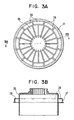
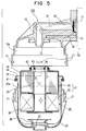
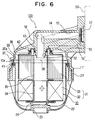
- An oil filter comprising:a bottomed cylindrical cap (202);a base (201) having a mounting portion (217) for mounting the cap;a first seal member (213) for providing a seal between the cap and the base; anda drain port (211) formed in the base at a side closer to a bottom side of the mounting portion than the first seal member.
- The oil filter as set forth in claim 11, further comprising:a second seal member (210) for providing a seal between an outlet (215) formed in the base and an element assembly (205) mounted in the cap.
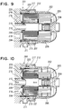
- The oil filter as set forth in claim 11 or 12, further comprising:a third seal member (204, 209) disposed closer to the bottom side of the mounting portion than the drain port for providing a seal between the cap and the base.
- The oil filter as set forth in claim 11 or 12, wherein a small gap is formed between the cap and the mounting portion of the base.
- The oil filter as set forth in any of claims 11 to 14, wherein the mounting portion has a groove (212) formed closer to its top side than the drain port and acting as an air vent.
- The oil filter as set forth in any of claims 11 to 15, wherein the first seal member is shaped cylindrically.
- A base for an oil filter comprising:a mounting portion (217) for mounting a cap (202) together with a filter element (206, 207);a seal portion (213) provided on the mounting portion for sealing between the mounting portion and the cap; anda drain port (211) formed at a side closer to a bottom of the mounting portion than the seal portion.
Applications Claiming Priority (6)
| Application Number | Priority Date | Filing Date | Title |
|---|---|---|---|
| JP30907896 | 1996-11-20 | ||
| JP309078/96 | 1996-11-20 | ||
| JP8309078A JPH10146503A (en) | 1996-11-20 | 1996-11-20 | Element assembly and element replacing type filter equipped therewith |
| JP18352197A JP3684770B2 (en) | 1997-07-09 | 1997-07-09 | Oil filter housing |
| JP18352197 | 1997-07-09 | ||
| JP183521/97 | 1997-07-09 |
Publications (3)
| Publication Number | Publication Date |
|---|---|
| EP0844012A2 true EP0844012A2 (en) | 1998-05-27 |
| EP0844012A3 EP0844012A3 (en) | 1999-05-06 |
| EP0844012B1 EP0844012B1 (en) | 2003-08-13 |
Family
ID=26501930
Family Applications (1)
| Application Number | Title | Priority Date | Filing Date |
|---|---|---|---|
| EP97118188A Expired - Lifetime EP0844012B1 (en) | 1996-11-20 | 1997-10-20 | Oil filter |
Country Status (2)
| Country | Link |
|---|---|
| EP (1) | EP0844012B1 (en) |
| DE (1) | DE69724076T2 (en) |
Cited By (16)
| Publication number | Priority date | Publication date | Assignee | Title |
|---|---|---|---|---|
| US6752924B2 (en) * | 2001-04-02 | 2004-06-22 | Donaldson Company, Inc. | Bowl-cartridge filter having interlock mechanism and methods |
| WO2005063358A2 (en) * | 2003-12-22 | 2005-07-14 | Donaldson Company, Inc. | Liquid filter assembly; and, methods |
| DE102005007024A1 (en) * | 2005-02-15 | 2006-08-24 | Mann + Hummel Gmbh | Liquid filtration system |
| WO2007089852A3 (en) * | 2006-01-30 | 2007-10-04 | Donaldson Co Inc | Filter arrangement and servicing thereof |
| WO2009043403A1 (en) * | 2007-09-27 | 2009-04-09 | Hydac Filtertechnik Gmbh | Filter device and filter element |
| WO2009067188A1 (en) * | 2007-11-19 | 2009-05-28 | Caterpillar Inc. | Fluid filter system |
| US20100032359A1 (en) * | 2006-12-04 | 2010-02-11 | Mann+Hummel Gmbh | Oil Filter, Oil Separator and Filter Insert Thereof |
| US20130081990A1 (en) * | 2011-10-04 | 2013-04-04 | Mann+Hummel Gmbh | Filter for Filtering Fluids, Filter Cup and Filter Head |
| US8794222B2 (en) | 2010-01-27 | 2014-08-05 | Cummins Filtration Ip, Inc. | Crankcase ventilation inside-out flow rotating coalescer |
| DE102013017302A1 (en) * | 2013-10-18 | 2015-04-23 | Mann + Hummel Gmbh | A filter assembly |
| FR3018202A1 (en) * | 2014-03-04 | 2015-09-11 | Cummins Filtration Sarl | FILTERING ASSEMBLY COMPRISING A FILTRATION CARTRIDGE |
| US20170296951A1 (en) * | 2014-08-28 | 2017-10-19 | Hengst Se & Co. Kg | Device for cleaning liquids or gaseous media and precipitating element for said device |
| US9802146B2 (en) | 2010-01-27 | 2017-10-31 | Cummins Filtration Ip, Inc. | Rotating separator with housing preventing separated liquid carryover |
| WO2020256869A1 (en) * | 2019-06-17 | 2020-12-24 | Caterpillar Inc. | Filter element having potted gasket end cap assembly |
| US20210062692A1 (en) * | 2019-08-29 | 2021-03-04 | Kohler Co. | Plural circuit oil filter |
| US11491423B2 (en) | 2004-04-13 | 2022-11-08 | Donaldson Company, Inc. | Filter cartridge for liquid filtration; assembly; and, methods |
Families Citing this family (9)
| Publication number | Priority date | Publication date | Assignee | Title |
|---|---|---|---|---|
| US8501003B2 (en) | 2007-10-17 | 2013-08-06 | Caterpillar Inc. | Canister filter system with drain that cooperates with filter element |
| US8157997B2 (en) | 2007-10-17 | 2012-04-17 | Caterpillar Inc. | Canister filter system with drain that cooperates with filter element |
| DE102008038602A1 (en) * | 2008-08-21 | 2010-04-15 | Ibs Filtran Kunststoff- / Metallerzeugnisse Gmbh | filter means |
| DE102009032849B4 (en) * | 2009-07-13 | 2015-07-23 | Ibs Filtran Kunststoff-/ Metallerzeugnisse Gmbh | Oil filter device with a de-oiling device |
| US8974567B2 (en) | 2010-01-27 | 2015-03-10 | Cummins Filtration Ip Inc. | Rotating coalescer with keyed drive |
| US9194265B2 (en) | 2010-01-27 | 2015-11-24 | Cummins Filtration Ip, Inc. | Rotating separator with housing preventing separated liquid carryover |
| US8940068B2 (en) | 2010-01-27 | 2015-01-27 | Cummins Filtration Ip Inc. | Magnetically driven rotating separator |
| US8893689B2 (en) | 2010-01-27 | 2014-11-25 | Cummins Filtration Ip, Inc. | Crankcase ventilation self-cleaning coalescer with intermittent rotation |
| DE102014010388A1 (en) * | 2014-07-14 | 2016-01-14 | Mann + Hummel Gmbh | Oil filter device and housing cover and housing pot of an oil filter device |
Citations (5)
| Publication number | Priority date | Publication date | Assignee | Title |
|---|---|---|---|---|
| EP0269895B1 (en) * | 1986-12-03 | 1991-06-26 | Robert Bosch Gmbh | Liquid-filter, in particular for fuels |
| EP0442365A2 (en) * | 1990-02-14 | 1991-08-21 | Stanadyne Automotive Corp. | Key system for filter assembly |
| DE4330839A1 (en) * | 1993-09-11 | 1995-03-16 | Hengst Walter Gmbh & Co Kg | Filter for the purification of liquids |
| EP0692292A1 (en) * | 1994-07-13 | 1996-01-17 | Ing. Walter Hengst GmbH & Co. KG | Filter for liquids |
| EP0702144A2 (en) * | 1994-09-13 | 1996-03-20 | Robert Bosch Gmbh | Replaceable filter element for cleaning fuel and filter casing for the installation of the replaceable filter element |
-
1997
- 1997-10-20 DE DE69724076T patent/DE69724076T2/en not_active Expired - Lifetime
- 1997-10-20 EP EP97118188A patent/EP0844012B1/en not_active Expired - Lifetime
Patent Citations (5)
| Publication number | Priority date | Publication date | Assignee | Title |
|---|---|---|---|---|
| EP0269895B1 (en) * | 1986-12-03 | 1991-06-26 | Robert Bosch Gmbh | Liquid-filter, in particular for fuels |
| EP0442365A2 (en) * | 1990-02-14 | 1991-08-21 | Stanadyne Automotive Corp. | Key system for filter assembly |
| DE4330839A1 (en) * | 1993-09-11 | 1995-03-16 | Hengst Walter Gmbh & Co Kg | Filter for the purification of liquids |
| EP0692292A1 (en) * | 1994-07-13 | 1996-01-17 | Ing. Walter Hengst GmbH & Co. KG | Filter for liquids |
| EP0702144A2 (en) * | 1994-09-13 | 1996-03-20 | Robert Bosch Gmbh | Replaceable filter element for cleaning fuel and filter casing for the installation of the replaceable filter element |
Cited By (38)
| Publication number | Priority date | Publication date | Assignee | Title |
|---|---|---|---|---|
| US6752924B2 (en) * | 2001-04-02 | 2004-06-22 | Donaldson Company, Inc. | Bowl-cartridge filter having interlock mechanism and methods |
| WO2005063358A2 (en) * | 2003-12-22 | 2005-07-14 | Donaldson Company, Inc. | Liquid filter assembly; and, methods |
| WO2005063358A3 (en) * | 2003-12-22 | 2005-08-25 | Donaldson Co Inc | Liquid filter assembly; and, methods |
| US9433881B2 (en) | 2003-12-22 | 2016-09-06 | Donaldson Company, Inc. | Liquid filter assembly; and, methods |
| US8119002B2 (en) | 2003-12-22 | 2012-02-21 | Donaldson Company, Inc. | Liquid filter assembly; and methods |
| US11491423B2 (en) | 2004-04-13 | 2022-11-08 | Donaldson Company, Inc. | Filter cartridge for liquid filtration; assembly; and, methods |
| DE102005007024A1 (en) * | 2005-02-15 | 2006-08-24 | Mann + Hummel Gmbh | Liquid filtration system |
| WO2007089852A3 (en) * | 2006-01-30 | 2007-10-04 | Donaldson Co Inc | Filter arrangement and servicing thereof |
| US20100032359A1 (en) * | 2006-12-04 | 2010-02-11 | Mann+Hummel Gmbh | Oil Filter, Oil Separator and Filter Insert Thereof |
| US8480892B2 (en) * | 2006-12-04 | 2013-07-09 | Mann + Hummel Gmbh | Oil filter, oil separator and filter insert thereof |
| WO2009043403A1 (en) * | 2007-09-27 | 2009-04-09 | Hydac Filtertechnik Gmbh | Filter device and filter element |
| EP2192966B1 (en) | 2007-09-27 | 2017-11-29 | Hydac Filtertechnik Gmbh | Filter device and filter element |
| CN101815566B (en) * | 2007-09-27 | 2014-06-25 | Hydac过滤技术有限公司 | Filter device and filter element |
| US8550255B2 (en) | 2007-09-27 | 2013-10-08 | Hydac Filtertechnik Gmbh | Filter device and filter element |
| US9089795B2 (en) | 2007-11-19 | 2015-07-28 | Caterpillar Inc. | Fluid filter system |
| US8540080B2 (en) | 2007-11-19 | 2013-09-24 | Caterpillar Inc. | Fluid filter system |
| WO2009067188A1 (en) * | 2007-11-19 | 2009-05-28 | Caterpillar Inc. | Fluid filter system |
| CN101861193B (en) * | 2007-11-19 | 2014-03-12 | 卡特彼勒公司 | Fluid filter system |
| US8272516B2 (en) | 2007-11-19 | 2012-09-25 | Caterpillar Inc. | Fluid filter system |
| US8794222B2 (en) | 2010-01-27 | 2014-08-05 | Cummins Filtration Ip, Inc. | Crankcase ventilation inside-out flow rotating coalescer |
| US10913023B2 (en) | 2010-01-27 | 2021-02-09 | Cummins Filtration Ip, Inc | Rotating separator with housing preventing separated liquid carryover |
| US9802146B2 (en) | 2010-01-27 | 2017-10-31 | Cummins Filtration Ip, Inc. | Rotating separator with housing preventing separated liquid carryover |
| US9885265B2 (en) | 2010-01-27 | 2018-02-06 | Cummins Filtration Ip Inc. | Crankcase ventilation inside-out flow rotating coalescer |
| US20130081990A1 (en) * | 2011-10-04 | 2013-04-04 | Mann+Hummel Gmbh | Filter for Filtering Fluids, Filter Cup and Filter Head |
| US9656194B2 (en) * | 2011-10-04 | 2017-05-23 | Mann+Hummel Gmbh | Filter for filtering fluids, filter cup and filter head |
| DE102013017302B4 (en) | 2013-10-18 | 2019-03-14 | Mann+Hummel Gmbh | A filter assembly |
| DE102013017302A1 (en) * | 2013-10-18 | 2015-04-23 | Mann + Hummel Gmbh | A filter assembly |
| WO2015132142A1 (en) * | 2014-03-04 | 2015-09-11 | Cummins Filtration Sarl | Filtering assembly comprising a filter cartridge |
| US9943790B2 (en) | 2014-03-04 | 2018-04-17 | Cummins Filtration Sarl | Filtering assembly comprising a filter cartridge |
| FR3057177A1 (en) * | 2014-03-04 | 2018-04-13 | Cummins Filtration Sarl | FILTERING ASSEMBLY COMPRISING A FILTRATION CARTRIDGE |
| US10661207B2 (en) | 2014-03-04 | 2020-05-26 | Cummins Filtration Sarl | Filtering assembly comprising a filter cartridge |
| US11452958B2 (en) | 2014-03-04 | 2022-09-27 | Cummins Filtrtion Sarl | Filtering assembly comprising a filter cartridge |
| FR3018202A1 (en) * | 2014-03-04 | 2015-09-11 | Cummins Filtration Sarl | FILTERING ASSEMBLY COMPRISING A FILTRATION CARTRIDGE |
| US20170296951A1 (en) * | 2014-08-28 | 2017-10-19 | Hengst Se & Co. Kg | Device for cleaning liquids or gaseous media and precipitating element for said device |
| WO2020256869A1 (en) * | 2019-06-17 | 2020-12-24 | Caterpillar Inc. | Filter element having potted gasket end cap assembly |
| CN113993606A (en) * | 2019-06-17 | 2022-01-28 | 卡特彼勒公司 | Filter element with potting washer end cap assembly |
| US20210062692A1 (en) * | 2019-08-29 | 2021-03-04 | Kohler Co. | Plural circuit oil filter |
| US11713699B2 (en) * | 2019-08-29 | 2023-08-01 | Kohler Co. | Plural circuit oil filter |
Also Published As
| Publication number | Publication date |
|---|---|
| EP0844012A3 (en) | 1999-05-06 |
| EP0844012B1 (en) | 2003-08-13 |
| DE69724076D1 (en) | 2003-09-18 |
| DE69724076T2 (en) | 2004-06-09 |
Similar Documents
| Publication | Publication Date | Title |
|---|---|---|
| EP0844012A2 (en) | Filter element assembly and element-replaceable type filter equipped with the same | |
| US7959010B2 (en) | Standpipe with integrated regulator valve | |
| JP3072436B2 (en) | Fuel filter device | |
| US5584987A (en) | Fluid filter assemblies | |
| US4500425A (en) | Pump valve for liquid separator | |
| US5180490A (en) | Lubricant filter assembly with internal bypass lock-out | |
| EP0839563B1 (en) | Fluid filter with drain valve | |
| EP0518865B1 (en) | Heavy duty air filter with multipurpose end seal | |
| US20050178716A1 (en) | Filter assembly and filter element with integral seal | |
| US5605624A (en) | Quick connect/disconnect liquid filter | |
| US8276763B2 (en) | Filter cartridge with flow passage in end plate | |
| US5006235A (en) | Barrier flange filter assembly including cover | |
| CA2669005C (en) | Fluid filter, fluid filter assembly, and mounting method | |
| JPH03157109A (en) | Fuel filter assembly and cartridge | |
| US20040256308A1 (en) | Fluid filtration system including replaceable filter module | |
| US20220379245A1 (en) | Advanced Fuel Filtration System with Interlocking Cartridge Seal Design | |
| EP0394585A2 (en) | Oil filter | |
| US11732658B2 (en) | Filter valve assembly | |
| GB1589235A (en) | Disposable filter canister and oil filter assembly which includes the canister | |
| US6911141B2 (en) | Low waste liquid filter | |
| CA2190076C (en) | Improvements in anti-drain back/pressure relieved filter cartridges | |
| US5690816A (en) | Anti-drain back/pressure relieved filter cartridges | |
| JP3684770B2 (en) | Oil filter housing | |
| JPH10146503A (en) | Element assembly and element replacing type filter equipped therewith | |
| JP3873435B2 (en) | Oil filter for engine |
Legal Events
| Date | Code | Title | Description |
|---|---|---|---|
| PUAI | Public reference made under article 153(3) epc to a published international application that has entered the european phase |
Free format text: ORIGINAL CODE: 0009012 |
|
| AK | Designated contracting states |
Kind code of ref document: A2 Designated state(s): DE FR GB |
|
| AX | Request for extension of the european patent |
Free format text: AL;LT;LV;RO;SI |
|
| PUAL | Search report despatched |
Free format text: ORIGINAL CODE: 0009013 |
|
| AK | Designated contracting states |
Kind code of ref document: A3 Designated state(s): AT BE CH DE DK ES FI FR GB GR IE IT LI LU MC NL PT SE |
|
| AX | Request for extension of the european patent |
Free format text: AL;LT;LV;RO;SI |
|
| 17P | Request for examination filed |
Effective date: 19990610 |
|
| AKX | Designation fees paid |
Free format text: DE FR GB |
|
| 17Q | First examination report despatched |
Effective date: 20010502 |
|
| GRAH | Despatch of communication of intention to grant a patent |
Free format text: ORIGINAL CODE: EPIDOS IGRA |
|
| RTI1 | Title (correction) |
Free format text: OIL FILTER |
|
| GRAH | Despatch of communication of intention to grant a patent |
Free format text: ORIGINAL CODE: EPIDOS IGRA |
|
| GRAA | (expected) grant |
Free format text: ORIGINAL CODE: 0009210 |
|
| AK | Designated contracting states |
Designated state(s): DE FR GB |
|
| REG | Reference to a national code |
Ref country code: GB Ref legal event code: FG4D |
|
| REF | Corresponds to: |
Ref document number: 69724076 Country of ref document: DE Date of ref document: 20030918 Kind code of ref document: P |
|
| ET | Fr: translation filed | ||
| PLBE | No opposition filed within time limit |
Free format text: ORIGINAL CODE: 0009261 |
|
| STAA | Information on the status of an ep patent application or granted ep patent |
Free format text: STATUS: NO OPPOSITION FILED WITHIN TIME LIMIT |
|
| 26N | No opposition filed |
Effective date: 20040514 |
|
| REG | Reference to a national code |
Ref country code: GB Ref legal event code: 746 Effective date: 20050210 |
|
| PGFP | Annual fee paid to national office [announced via postgrant information from national office to epo] |
Ref country code: FR Payment date: 20131022 Year of fee payment: 17 Ref country code: GB Payment date: 20131021 Year of fee payment: 17 Ref country code: DE Payment date: 20131021 Year of fee payment: 17 |
|
| REG | Reference to a national code |
Ref country code: DE Ref legal event code: R119 Ref document number: 69724076 Country of ref document: DE |
|
| GBPC | Gb: european patent ceased through non-payment of renewal fee |
Effective date: 20141020 |
|
| PG25 | Lapsed in a contracting state [announced via postgrant information from national office to epo] |
Ref country code: GB Free format text: LAPSE BECAUSE OF NON-PAYMENT OF DUE FEES Effective date: 20141020 Ref country code: DE Free format text: LAPSE BECAUSE OF NON-PAYMENT OF DUE FEES Effective date: 20150501 |
|
| REG | Reference to a national code |
Ref country code: FR Ref legal event code: ST Effective date: 20150630 |
|
| PG25 | Lapsed in a contracting state [announced via postgrant information from national office to epo] |
Ref country code: FR Free format text: LAPSE BECAUSE OF NON-PAYMENT OF DUE FEES Effective date: 20141031 |